CN113264099B - stroller - Google Patents
stroller Download PDFInfo
- Publication number
- CN113264099B CN113264099B CN202110354960.8A CN202110354960A CN113264099B CN 113264099 B CN113264099 B CN 113264099B CN 202110354960 A CN202110354960 A CN 202110354960A CN 113264099 B CN113264099 B CN 113264099B
- Authority
- CN
- China
- Prior art keywords
- frame
- seat
- rod
- center line
- backrest
- Prior art date
- Legal status (The legal status is an assumption and is not a legal conclusion. Google has not performed a legal analysis and makes no representation as to the accuracy of the status listed.)
- Active
Links
Images




Classifications
-
- B—PERFORMING OPERATIONS; TRANSPORTING
- B62—LAND VEHICLES FOR TRAVELLING OTHERWISE THAN ON RAILS
- B62B—HAND-PROPELLED VEHICLES, e.g. HAND CARTS OR PERAMBULATORS; SLEDGES
- B62B7/00—Carriages for children; Perambulators, e.g. dolls' perambulators
- B62B7/04—Carriages for children; Perambulators, e.g. dolls' perambulators having more than one wheel axis; Steering devices therefor
- B62B7/06—Carriages for children; Perambulators, e.g. dolls' perambulators having more than one wheel axis; Steering devices therefor collapsible or foldable
- B62B7/064—Carriages for children; Perambulators, e.g. dolls' perambulators having more than one wheel axis; Steering devices therefor collapsible or foldable the handle bar being parallel to the front leg
-
- B—PERFORMING OPERATIONS; TRANSPORTING
- B62—LAND VEHICLES FOR TRAVELLING OTHERWISE THAN ON RAILS
- B62B—HAND-PROPELLED VEHICLES, e.g. HAND CARTS OR PERAMBULATORS; SLEDGES
- B62B2205/00—Hand-propelled vehicles or sledges being foldable or dismountable when not in use
- B62B2205/12—Collapsible wheels
Landscapes
- Engineering & Computer Science (AREA)
- Chemical & Material Sciences (AREA)
- Combustion & Propulsion (AREA)
- Transportation (AREA)
- Mechanical Engineering (AREA)
- Carriages For Children, Sleds, And Other Hand-Operated Vehicles (AREA)
Abstract
本发明公开了一种儿童推车,包括具有展开状态与折叠状态的车架、设置在车架上的座位架,车架处于展开状态下,座位架包括座位与靠背,靠背的下部转动地设置有靠背安装座,靠背安装座能够沿座位的长度延伸方向相对运动地设置在座位上,车架由展开状态向折叠状态转换的过程中,靠背安装座沿座位向前运动,靠背与座位相互收拢并与车架收拢在一起。本发明与现有技术相比至少具有下列优点:1、车架折叠时够联动座位架折叠,操作简便;2、折叠状态下,靠背与座位相互贴合,并与车架收拢在一起,整车折叠体积小,便于携带和存储;3、靠背可以一体设置,结构简单并保证了支撑强度。

The invention discloses a children's stroller, comprising a frame with unfolded and folded states, and a seat frame arranged on the frame. When the frame is in the unfolded state, the seat frame includes a seat and a backrest, and the lower part of the backrest is rotatably arranged There is a backrest mounting seat, and the backrest mounting seat can be arranged on the seat in a relative movement along the length extension direction of the seat. During the transition of the frame from the unfolded state to the folded state, the backrest mounting seat moves forward along the seat, and the backrest and the seat are folded together. and folded together with the frame. Compared with the prior art, the present invention has at least the following advantages: 1. When the vehicle frame is folded, the seat frame can be folded in conjunction, and the operation is simple; The folding size of the car is small, which is easy to carry and store; 3. The backrest can be set in one piece, the structure is simple and the support strength is guaranteed.
Description
技术领域technical field
本发明涉及儿童用品领域,尤其涉及一种儿童推车。The invention relates to the field of children's products, in particular to a children's stroller.
背景技术Background technique
现有的可折叠的儿童推车,其座椅的折叠方式通常是一个难点,某些推车折叠时需要将座椅拆卸下来,操作复杂;一些推车为了减小车架折叠后的体积,会将座椅的靠背设计为上下分段式,靠背本体及头托两部分通过转轴连接,这样设计的靠背,一方面使得座椅的结构复杂,增加了生产成本且不便于使用,另一方面降低了靠背的支撑强度,缺陷明显。In the existing foldable baby strollers, the folding method of the seat is usually a difficult point. When some strollers are folded, the seat needs to be removed, which is complicated to operate; in order to reduce the volume of the folded frame of some strollers, The backrest of the seat will be designed to be segmented up and down, and the body of the backrest and the headrest will be connected by a rotating shaft. The backrest designed in this way, on the one hand, makes the structure of the seat complicated, increases the production cost and is inconvenient to use, on the other hand The support strength of the backrest is reduced, and the defects are obvious.
发明内容SUMMARY OF THE INVENTION
本发明的目的是提供一种座椅折叠方式简单、折叠体积小的儿童推车。The purpose of the present invention is to provide a child stroller with a simple folding method of the seat and a small folding volume.
为达到上述目的,本发明采用的技术方案是:To achieve the above object, the technical scheme adopted in the present invention is:
一种儿童推车,包括具有展开状态与折叠状态的车架、设置在所述车架上的座位架,所述车架处于展开状态下,所述座位架包括座位与靠背,所述靠背的下部转动地设置有靠背安装座,所述靠背安装座能够沿所述座位的长度延伸方向相对运动地设置在所述座位上,所述车架由展开状态向折叠状态转换的过程中,所述靠背安装座沿所述座位向前运动,所述靠背与所述座位相互收拢并与所述车架收拢在一起。A children's stroller includes a frame with an unfolded state and a folded state, a seat frame arranged on the frame, the frame is in the unfolded state, the seat frame includes a seat and a backrest, and the backrest has a seat and a backrest. The lower part is rotatably provided with a backrest mounting seat, and the backrest mounting seat is arranged on the seat so as to be relatively movable along the extending direction of the length of the seat. During the transition of the frame from the unfolded state to the folded state, the A backrest mount moves forward along the seat, the backrest and the seat being folded with each other and with the frame.
优选地,所述座位具有坐立面,所述靠背具有分设于自身厚度方向相异两侧的靠背面与背侧面,当所述车架处于折叠状态时,所述背侧面与所述坐立面相对合拢。Preferably, the seat has a sitting surface, and the backrest has a backrest surface and a back surface respectively disposed on two sides with different thickness directions of the seat. When the frame is in a folded state, the back surface and the sitting-stand Faces close together.
优选地,所述靠背安装座能够沿前后方向相对滑动地设置在所述座位上,所述车架上具有用于在所述车架在所述展开状态与所述折叠状态之间切换的过程中驱使所述靠背安装座相对所述座位滑动的驱动机构。Preferably, the backrest mounting seat is relatively slidable on the seat in the front-rear direction, and the frame has a process for switching the frame between the unfolded state and the folded state A drive mechanism for driving the backrest mount to slide relative to the seat.
进一步优选地,所述车架至少具有第一杆架与第二杆架,所述座位的后部绕第一转动中心线转动地连接在所述第一杆架上,所述座位既能够沿前后方向相对滑动又能够绕第二转动中心线相对转动地连接在所述第二杆架上,所述第二转动中心线与所述第一转动中心线相互平行并位于所述第一转动中心线的前方,所述车架在由展开状态向折叠状态转换的过程中,所述第一转动中心线与所述第二转动中心线沿前后方向相互远离,所述驱动机构包括驱动杆,所述驱动杆的一端部转动地连接在所述靠背安装座上,所述驱动杆的另一端部转动地连接在所述车架上并在所述车架在由展开状态向折叠状态转换的过程中远离所述第一转动中心线运动。Further preferably, the vehicle frame has at least a first rod frame and a second rod frame, the rear of the seat is rotatably connected to the first rod frame around a first rotation center line, and the seat can be The front and rear directions are relatively slidable and can be relatively rotatably connected to the second rod frame around the second rotation center line. The second rotation center line and the first rotation center line are parallel to each other and located at the first rotation center. In front of the line, during the transition of the frame from the unfolded state to the folded state, the first rotation center line and the second rotation center line are far away from each other in the front-rear direction, and the driving mechanism includes a driving rod, so One end of the drive rod is rotatably connected to the backrest mounting seat, and the other end of the drive rod is rotatably connected to the frame, and the frame is in the process of transitioning from the unfolded state to the folded state moving away from the first rotational centerline.
更进一步优选地,所述驱动杆的所述另一端部绕第三转动中心线转动地连接在所述第二杆架上,所述第三转动中心线与所述第二转动中心线相互平行或共线延伸。Further preferably, the other end of the driving rod is rotatably connected to the second rod frame around a third rotation center line, and the third rotation center line and the second rotation center line are parallel to each other. or collinear extension.
更进一步优选地,所述第二杆架上设置有沿左右方向延伸的支撑杆,所述座位包括座板、固设于所述座板底部的导向杆,所述导向杆与所述座板之间形成沿前后方向延伸的导向槽,所述支撑杆既能够相对转动又能够沿前后方向滑动配合地插设在所述导向槽中,且所述支撑杆支撑在所述座板的下方。Further preferably, the second rod frame is provided with a support rod extending in the left-right direction, the seat includes a seat plate, a guide rod fixed on the bottom of the seat plate, the guide rod is connected to the seat plate A guide groove extending in the front-rear direction is formed therebetween, the support rod can be relatively rotatable and can be slidably fitted in the guide groove in the front-rear direction, and the support rod is supported under the seat plate.
优选地,所述车架包括各自沿上下方向延伸的前支架、后支架、扶手架,所述前支架的上部、所述后支架的上部及所述扶手架的下部这三者中的两者转动连接且第三者与前述两者中的一者转动地连接,或者所述前支架的上部、所述后支架的上部及所述扶手架的下部这三者相互转动地连接在一起,所述前支架、所述后支架、所述扶手架中的一者构成所述的第二杆架。Preferably, the frame includes a front bracket, a rear bracket, and an armrest frame each extending in an up-down direction, and two of the upper part of the front bracket, the upper part of the rear bracket, and the lower part of the armrest frame The third party is rotatably connected with one of the aforementioned two, or the upper part of the front bracket, the upper part of the rear bracket and the lower part of the armrest frame are rotatably connected to each other, so One of the front bracket, the rear bracket and the armrest frame constitutes the second pole frame.
进一步优选地,所述车架还包括各自沿上下方向延伸的推杆架与后撑架,以及设置在所述前支架与所述后支架之间的连杆组件,所述扶手架的上部转动地连接在所述推杆架上,所述后撑架与所述后支架转动地连接,所述推杆架的下部与所述后撑架的上部转动地连接,所述连杆组件包括前连杆与后连杆,所述前连杆的前部转动地连接所述前支架,所述后连杆的后部转动地连接所述后支架,所述前连杆的后部与所述后连杆的前部转动地连接,所述后撑架的下部既能相对转动又能够相对滑动地连接在所述后连杆上,所述后撑架构成所述的第一杆架。Further preferably, the vehicle frame further includes a push rod frame and a rear support frame respectively extending in the up-down direction, and a link assembly arranged between the front frame and the rear frame, and the upper part of the armrest frame rotates connected to the push rod frame, the rear support frame is rotatably connected to the rear support frame, the lower part of the push rod frame is rotatably connected to the upper part of the rear support frame, and the connecting rod assembly includes a front connecting rod and rear connecting rod, the front part of the front link is rotatably connected to the front bracket, the rear part of the rear link is rotatably connected to the rear bracket, and the rear part of the front link is connected to the The front part of the rear link is rotatably connected, and the lower part of the rear support frame is connected to the rear link in a relatively rotatable and slidable manner, and the rear support frame constitutes the first rod frame.
优选地,所述车架包括各自沿上下方向延伸的前支架、后支架、扶手架、推杆架、后撑架,其中,所述前支架的上部、所述后支架的上部及所述扶手架的下部这三者中的两者转动连接且第三者与前述两者中的一者转动地连接,或者所述前支架的上部、所述后支架的上部及所述扶手架的下部这三者相互转动地连接在一起,所述扶手架的上部转动地连接在所述推杆架上,所述后撑架与所述后支架转动地连接,所述推杆架的下部与所述后撑架的上部转动地连接,所述前支架的上部、所述后支架的上部及所述扶手架的下部这三者中的一者上设置有支撑杆,所述支撑杆既能够相对转动又能够沿前后方向相对滑动地与所述座位连接,所述座位的后部转动地连接在所述后撑架上,所述靠背安装座能够沿前后方向相对滑动地设置在所述座位上,所述车架还包括驱动杆,所述驱动杆的一端部转动地连接在所述靠背安装座上,所述驱动杆的另一端部转动地连接在所述前支架的上部、所述后支架的上部及所述扶手架的下部这三者中的一者上。Preferably, the vehicle frame includes a front bracket, a rear bracket, an armrest bracket, a push rod bracket, and a rear bracket each extending in an up-down direction, wherein the upper part of the front bracket, the upper part of the rear bracket and the armrest Two of the lower part of the frame are rotationally connected and the third is rotationally connected to one of the aforementioned two, or the upper part of the front frame, the upper part of the rear frame and the lower part of the armrest frame are The three are rotatably connected to each other, the upper part of the armrest frame is rotatably connected to the push rod frame, the rear bracket is rotatably connected to the rear bracket, and the lower part of the push rod frame is rotatably connected to the The upper part of the rear bracket is rotatably connected, and one of the upper part of the front bracket, the upper part of the rear bracket and the lower part of the armrest frame is provided with a support rod, and the support rod can rotate relatively The seat can be relatively slidably connected to the seat in the front-rear direction, the rear part of the seat is rotatably connected to the rear support frame, and the backrest mounting seat can be relatively slidably arranged on the seat in the front-rear direction, The frame also includes a drive rod, one end of the drive rod is rotatably connected to the backrest mounting seat, and the other end of the drive rod is rotatably connected to the upper part of the front bracket and the rear bracket on one of the upper part and the lower part of the armrest frame.
进一步优选地,所述扶手架的下部与所述后支架的上部转动地连接,所述支撑杆设于所述后支架的上部或所述扶手架的下部,当所述车架处于折叠状态时,所述座位与所述靠背相互靠拢并与所述后支架及所述后撑架相互收拢。Further preferably, the lower part of the armrest frame is rotatably connected with the upper part of the rear bracket, and the support rod is provided on the upper part of the rear bracket or the lower part of the armrest frame, when the vehicle frame is in a folded state , the seat and the backrest are close to each other, and the rear bracket and the rear support frame are closed to each other.
由于上述技术方案的运用,本发明提供的儿童推车,通过设置能够沿座位的长度延伸方向相对运动的靠背安装座,当车架折叠时,能够联动靠背与座位相互收拢,本发明与现有技术相比至少具有下列优点:1、车架折叠时够联动座位架折叠,操作简便;2、折叠状态下,靠背与座位相互贴合,并与车架收拢在一起,整车折叠体积小,便于携带和存储;3、靠背可以一体设置,结构简单并保证了支撑强度。Due to the application of the above technical solutions, the stroller provided by the present invention is provided with a backrest mounting seat that can move relatively along the length extension direction of the seat. When the frame is folded, the backrest and the seat can be linked together to fold together. The present invention is different from the existing one. Compared with the technology, it has at least the following advantages: 1. When the frame is folded, the seat frame can be folded together, which is easy to operate; 2. In the folded state, the backrest and the seat are attached to each other and folded together with the frame, and the folded volume of the whole vehicle is small. Easy to carry and store; 3. The backrest can be set in one piece, the structure is simple and the support strength is guaranteed.
附图说明Description of drawings
为了更清楚地说明本发明的技术方案,下面将对实施例描述中所需要使用的附图作简单的介绍,显而易见地,下面描述中的附图仅仅是本发明的一些实施例,对于本领域普通技术人员来讲,在不付出创造性劳动的前提下,还可以根据这些附图获得其他的附图。In order to illustrate the technical solutions of the present invention more clearly, the following briefly introduces the accompanying drawings used in the description of the embodiments. Obviously, the accompanying drawings in the following description are only some embodiments of the present invention, which are very important in the art. For those of ordinary skill, other drawings can also be obtained from these drawings without any creative effort.
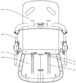
附图1为本发明的儿童推车一具体实施例展开状态下的立体示意图;Accompanying drawing 1 is a three-dimensional schematic diagram of a specific embodiment of the stroller of the present invention under the unfolded state;
附图2为图1中儿童推车的侧视示意图;Accompanying drawing 2 is the side view schematic diagram of the stroller in FIG. 1;
附图3为图1中儿童推车另一角度的立体示意图;Accompanying
附图4为本实施例中儿童推车折叠过程中的立体示意图;
附图5为图4中儿童推车的侧视示意图;5 is a schematic side view of the stroller in FIG. 4;
附图6为本实施例中儿童推车折叠状态下的立体示意图;6 is a perspective view of the stroller in the folded state of the present embodiment;
附图7为图6中儿童推车的侧视示意图;7 is a schematic side view of the stroller in FIG. 6;
附图8为本实施例中座位架及部分车架的结构分解立体示意图;8 is a schematic exploded perspective view of the structure of the seat frame and part of the vehicle frame in this embodiment;
附图9为本实施例中座位架及部分车架折叠过程中的立体示意图;FIG. 9 is a schematic perspective view of the seat frame and part of the vehicle frame in the process of folding in this embodiment;
附图10为图9的俯视示意图;10 is a schematic top view of FIG. 9;
附图11为本实施例中座位架及部分车架进一步折叠过程中的立体示意图;FIG. 11 is a schematic perspective view of the seat frame and part of the vehicle frame in the process of further folding in this embodiment;
附图12为本实施例中座位架及部分车架折叠状态下的立体示意图;Fig. 12 is a perspective view of the seat frame and part of the vehicle frame in a folded state in this embodiment;
附图13为本实施例中踏脚架及部分车架的结构分解立体示意图;Fig. 13 is a schematic exploded perspective view of the structure of the pedal frame and part of the vehicle frame in this embodiment;
附图14为本实施例中踏脚架及部分车架的展开状态下的立体示意图;14 is a perspective view of the pedal frame and part of the frame in the unfolded state of the present embodiment;
附图15为图14中A处放大示意图;Accompanying drawing 15 is the enlarged schematic diagram of place A in FIG. 14;
附图16为本实施例中踏脚架及部分车架的折叠过程中的立体示意图;FIG. 16 is a schematic perspective view of the step frame and part of the frame during the folding process of this embodiment;
附图17为本实施例中踏脚架及部分车架的折叠状态下的立体示意图;17 is a perspective view of the pedal frame and part of the frame in the folded state of the present embodiment;
其中:100、座位架;110、座位;110a、坐立面;120、靠背;120a、靠背面;120b、背侧面;130、腿托;200、踏脚架;210、收容槽;220、踏板连接部;310、前支架;311、前支杆;320、后支架;321、后支杆;3211、后支杆接头;410、扶手架;411、支撑杆;4111、驱动杆接头;412、扶手杆;420、推杆架;430、后撑架;431、后上撑杆;432、后横杆;433、后下撑杆;600、驱动杆;700、连杆组件;710、前连杆;711、主体杆部;712、驱动杆部;720、后连杆;730、滑动件;Among them: 100, seat frame; 110, seat; 110a, sitting surface; 120, backrest; 120a, backrest; 120b, back side; 130, leg rest; 200, footrest; 210, receiving slot; 220, pedal Connection part; 310, front bracket; 311, front strut; 320, rear bracket; 321, rear strut; 3211, rear strut joint; 410, armrest frame; 411, support rod; 4111, drive rod joint; 412, Grab bar; 420, push rod frame; 430, rear support frame; 431, rear upper stay bar; 432, rear cross bar; 433, rear lower stay bar; 600, drive bar; 700, connecting rod assembly; 710, front connection rod; 711, the main body rod; 712, the driving rod; 720, the rear link; 730, the slider;
11、座板;12、导向杆;2、靠背安装座;21、上安装座;211、销轴;22、下安装座;23、滑槽;3、前轮组件;31、前轮接头;32、前轮轮体;4、后轮组件;41、后轮接头;42、后轮轮体;51、连接凸柱;52、第一导槽;61、联动杆;62、第二导槽;63、连接件;64、限位件;11, seat plate; 12, guide rod; 2, backrest mounting seat; 21, upper mounting seat; 211, pin shaft; 22, lower mounting seat; 23, chute; 3, front wheel assembly; 31, front wheel joint; 32. Front wheel body; 4. Rear wheel assembly; 41, Rear wheel joint; 42, Rear wheel body; ; 63, connecting piece; 64, limit piece;
X、第一转动中心线;Y、第二转动中心线;Z、第三转动中心线;P、第四转动中心线;Q、第五转动中心线;R、第六转动中心线;S、前支杆轴心线。X, the first rotation center line; Y, the second rotation center line; Z, the third rotation center line; P, the fourth rotation center line; Q, the fifth rotation center line; R, the sixth rotation center line; S, Front strut axis.
具体实施方式Detailed ways
下面结合附图对本发明的较佳实施例进行详细阐述,以使本发明的优点和特征能更易于被本领域的技术人员理解。The preferred embodiments of the present invention will be described in detail below with reference to the accompanying drawings, so that the advantages and features of the present invention can be more easily understood by those skilled in the art.
在本发明的描述中,需要说明的是,术语“中心”、“上”、“下”、“左”、“右”、“竖直”、“水平”、“内”、“外”、“左右方向”、“高度方向”、“前后方向”等指示的方位或位置关系为基于附图1,儿童正常乘坐在该儿童推车上时,儿童所观察到的方位或位置关系,仅是为了便于描述本发明和简化描述,而不是指示或暗示所指的装置或元件必须具有特定的方位、仅具有特定的方位、以特定的方位构造和操作,因此不能理解为对本发明的限制。此外,术语“第一”、“第二”、“第三”等仅用于描述目的,而不能理解为指示或暗示相对重要性。In the description of the present invention, it should be noted that the terms "center", "upper", "lower", "left", "right", "vertical", "horizontal", "inner", "outer", The orientation or positional relationship indicated by "left-right direction", "altitude direction", "front-rear direction", etc. is based on Fig. 1. When the child normally rides on the stroller, the orientation or positional relationship observed by the child is only For the convenience of describing the present invention and simplifying the description, it is not indicated or implied that the indicated device or element must have a particular orientation, only have a particular orientation, be constructed and operate in a particular orientation, and therefore should not be construed as limiting the invention. Furthermore, the terms "first," "second," "third," etc. are used for descriptive purposes only and should not be construed to indicate or imply relative importance.
需要说明的是,如无特殊说明,当某一特征被称为“固定”、“连接”在另一个特征,它可以直接固定、连接在另一个特征上,也可以间接地固定、连接在另一个特征上。除非另有明确的规定和限定,术语“安装”、“相连”、“连接”应做广义理解,例如,可以是固定连接,也可以是可拆卸连接,或一体地连接;可以是机械连接,也可以是电连接;可以是直接相连,也可以通过中间媒介间接相连,可以是两个元件内部的连通。对于本领域的普通技术人员而言,可以具体情况理解上述术语在本发明中的具体含义。此外,本发明中所使用的上、下、左、右等描述仅仅是相对于附图中本发明各组成部分的相互位置关系来说的。It should be noted that, unless otherwise specified, when a feature is called "fixed" or "connected" to another feature, it can be directly fixed or connected to another feature, or it can be indirectly fixed or connected to another feature. on a feature. Unless otherwise expressly specified and limited, the terms "installed", "connected" and "connected" should be understood in a broad sense, for example, it may be a fixed connection, a detachable connection, or an integral connection; it may be a mechanical connection, It can also be an electrical connection; it can be a direct connection, an indirect connection through an intermediate medium, or an internal connection between two components. For those of ordinary skill in the art, the specific meanings of the above terms in the present invention can be understood in specific situations. In addition, the descriptions of upper, lower, left, right, etc. used in the present invention are only relative to the mutual positional relationship of each component of the present invention in the accompanying drawings.
参见图1至图3所示,一种儿童推车,包括具有展开状态与折叠状态的车架,以及设置在车架底部的车轮组件。展开状态下,车架包括各自沿上下方向延伸的前支架310、后支架320、扶手架410、推杆架420及后撑架430。Referring to FIGS. 1 to 3 , a child stroller includes a frame having an unfolded state and a folded state, and a wheel assembly disposed at the bottom of the frame. In the unfolded state, the vehicle frame includes a
其中,前支架310的上部、后支架320的上部及扶手架410的下部这三者中的两者转动连接,且第三者与前述两者中的一者转动地连接,或者前支架310的上部、后支架320的上部及扶手架410的下部这三者相互转动地连接在一起。Wherein, two of the upper part of the
本实施例中,前支架310具有分设于左右两侧且均沿上下方向延伸的两根前支杆311,后支架320具有分设于左右两侧且均沿上下方向延伸的两根后支杆321,每根后支杆321的上端部固设有后支杆接头3211,每侧的前支杆311绕转动线c与后支杆接头3211转动连接,转动线c沿车架的左右方向延伸。In the present embodiment, the
参见图5及图8所示,扶手架410具有分设于左右两侧且均沿上下方向延伸的两根扶手杆412,以及连接在两侧的扶手杆412下端部之间的支撑杆411。扶手杆412的上部绕转动线a转动地连接在推杆架420上,支撑杆411绕第二转动中心线Y(即支撑杆411自身的轴心线)转动连接在两个后支杆接头3211之间。Referring to FIGS. 5 and 8 , the
后撑架430具有分设于左右两侧且均沿上下方向延伸的两根后上撑杆431及两根后下撑杆433,以及沿左右方向延伸的后横杆432,后上撑杆431自后横杆432的左右两端部向上延伸,后下撑杆433自后横杆432向下延伸,并且在后横杆432的左右方向上,两根后下撑杆433位于两根后上撑杆431的内侧,上述后撑架430的各杆件相互固定。后上撑杆431的上端部绕转动线b与推杆架420的下端部转动连接,转动线b与转动线a相互平行,且转动线b位于转动线a的下方;在车架的左右方向上,两根后上撑杆431位于两根扶手杆412的内侧。参见图3所示,每侧的后下撑杆433绕转动线j与后支杆321转动地连接,在车架的左右方向上,两根后下撑杆433位于两根后支杆321的内侧。The
参见图1至图3及图13所示,车架还包括设置在前支架310与后支架320之间的连杆组件700,连杆组件700具有分设于左右两侧的两组,每组连杆组件700均包括各自沿前后方向延伸的前连杆710与后连杆720,其中前连杆710具有主体杆部711,以及自主体杆部711的前端向下并向后弯折延伸的驱动杆部712。具体地,前连杆710的前部绕第五转动中心线Q与前支杆311转动地连接,前连杆710的后端部绕转动线d与后连杆720的前端部转动连接,后连杆720的后部绕转动线f转动连接在后支杆321上,在后支杆321的长度方向上,转动线f位于转动线j的下方。此外,后撑架430的下部既能够相对转动又能够相对滑动地连接在后连杆720上,具体地,后支杆321上还设有能够沿后支杆321的长度方向滑动的滑动件730,后下撑杆433的下端部绕转动线e转动连接在滑动件730上。Referring to FIGS. 1 to 3 and 13 , the frame further includes a
本实施例中,车轮组件包括分设于两组前支杆311底部的两组前轮组件3,以及分设于两组后支杆321底部的两组后轮组件4。其中,前轮组件3包括前轮接头31与前轮轮体32,前轮接头31绕前支杆311的轴心线S相对转动地设于前支杆311的底部;相似地,后轮组件4包括后轮接头41与后轮轮体42,后轮接头41绕后支杆321的轴心线相对转动地设于后支杆321的底部。参见图6及图7所示,车架上设有车轮联动结构(图中未示出),当车架整体折叠时,前轮组件3及后轮组件4能够绕各自的转动中心线向内翻转,并与车架整体扁平地收拢在一起,使得车架折叠后体积极小。该车轮联动结构的具体可采用现有技术(例如申请公布号为CN109178077A的专利申请),本发明不作限定。In this embodiment, the wheel assemblies include two sets of
为了进一步优化车架的折叠结构,本实施例中,儿童推车还包括设置在车架上的座位架100,座位架100在左右方向上位于两侧的后上撑杆431之间。车架处于展开状态下,座位架100包括座位110、靠背120及腿托130,其中,座位110具有朝上的坐立面110a,靠背120具有分设于自身厚度方向相异两侧的靠背面120a与背侧面120b;腿托130绕转动线i转动连接在座位110的前端部;靠背120的下部转动地设置有靠背安装座2,靠背安装座2能够沿座位110的长度延伸方向相对运动地设置在座位110上。In order to further optimize the folding structure of the frame, in this embodiment, the stroller further includes a
车架处于展开状态下,儿童能够正常乘坐在该座位架100上,靠背120支撑背部,腿托130支撑腿部;车架折叠时,靠背120贴合收拢于座位110上部,腿托130贴合收拢于座位110下部。When the frame is in the unfolded state, the child can normally ride on the
车架至少具有第一杆架与第二杆架,座位110的后部绕第一转动中心线X转动地连接在第一杆架上,座位110既能够沿前后方向相对滑动又能够绕第二转动中心线Y相对转动地连接在第二杆架上,第二转动中心线Y与第一转动中心线X相互平行并位于第一转动中心线X的前方,当车架折叠时,第一转动中心线X与第二转动中心线Y相互远离。The frame has at least a first rod frame and a second rod frame, the rear of the
本实施例中,后撑架430构成第一杆架;前支架310、后支架320、扶手架410中的一者构成第二杆架,本实施例中具体是扶手架410构成第二杆架。In this embodiment, the
在其他实施例中,支撑杆411也可以设置在前支架310的上部或后支架320的上部,具有支撑杆411一者即可构成第二杆架。In other embodiments, the
参见图8至图12所示,具体地,靠背安装座2具有分设于靠背120左右两侧的两组,每组靠背安装座2包括相互固定设置的上安装座21、下安装座22及销轴211,其中,销轴211位于上安装座21与下安装座22之间,靠背120的下端部与上安装座21绕转动线h转动地连接,转动线h沿座位架100的左右方向延伸。Referring to FIGS. 8 to 12 , specifically, the backrest mounting seat 2 has two groups that are respectively arranged on the left and right sides of the
座位110包括座板11、固设于座板11底部的导向杆12,导向杆12与座板11之间形成沿前后方向延伸的导向槽,本实施例中,导向杆12具有沿左右方向间隔设置的两个,支撑杆411支撑在座板11的下方,支撑杆411既能够相对转动又能够沿前后方向滑动配合地插设在导向槽中,导向杆12为支撑杆411提供滑动导向。The
值得说明的是,本实施例中,扶手架410的扶手杆412及支撑杆411为一体设置,从而支撑杆411既能够相对转动又能够沿前后方向滑动配合地插设在导向槽中,如此设计时扶手架410的刚性较好。不过在其他的实施例中,支撑杆411也可以绕第二转动中心线Y转动地连接在两侧的扶手杆412下端部之间,这种情况下,支撑杆411仅滑动配合地插设在导向槽中,从而支撑杆411还可以设计成横截面为方形、三角形等任意形状的异形杆。It is worth noting that, in this embodiment, the
座板11上开设有两条沿前后方向延伸的滑槽23,两条滑槽23相互平行且分设于左右两侧,上述上安装座21位于滑槽23的上侧,下安装座22位于滑槽23的下侧,销轴211穿设在对应的滑槽23中,从而靠背安装座2能够沿滑槽23前后滑动,并带动靠背120沿座位110前后滑动。The
本实施例中,车架上还具有用于在车架在展开状态与折叠状态之间切换的过程中驱使靠背安装座2相对座位110滑动的驱动机构。In this embodiment, the vehicle frame further has a driving mechanism for driving the backrest mounting seat 2 to slide relative to the
具体地,驱动机构包括驱动杆600,驱动杆600的一端部转动地连接在靠背安装座2上,驱动杆600的另一端部转动地连接在车架上并在车架在由展开状态向折叠状态转换的过程中远离第一转动中心线X运动,实际上,驱动杆600的另一端部可以转动地连接在前支架310的上部、后支架320的上部及扶手架410的下部这三者中的一者上,更进一步地,驱动杆600的另一端部是转动地连接在支撑杆411上。Specifically, the driving mechanism includes a driving
本实施例中,驱动杆600具有与两个靠背安装座2相配合的两根,支撑杆411上固设有两个向下延伸的驱动杆接头4111。每根驱动杆600的后端部绕转动线g转动地连接在下安装座22上,驱动杆600的前端部绕第三转动中心线Z转动地连接在驱动杆接头4111上,转动线g、第三转动中心线Z、第二转动中心线Y相互平行,且第三转动中心线Z位于第二转动中心线Y的下方,在其他实施例中,第三转动中心线Z与第二转动中心线Y也可以共线延伸。In this embodiment, the driving
参见图13至图17所示,另一方面,该儿童推车还包括设于前支架310上的踏脚架200,可供儿童放置双脚,踏脚架200能够沿前支架310的长度延伸方向相对滑动地设置在前支架310上。车架处于展开状态下,踏脚架200在前支架310上处于第一位置;车架处于折叠状态下,踏脚架200在前支架310上处于第二位置,第一位置在前支架310上位于第二位置的下方,车架上还设有用于在车架在展开状态与折叠状态之间转换的过程中驱使踏脚架200相对前支架310滑动的联动机构。Referring to FIGS. 13 to 17 , on the other hand, the stroller further includes a
具体地,联动机构包括联动架,联动架绕第四转动中心线P转动地与踏脚架200连接,联动架能够相对滑动地连接在前支架310上;前连杆710的驱动杆部712的前端部绕第六转动中心线R与联动架转动地连接,第五转动中心线Q位于前连杆710的主体杆部711与驱动杆部712的相接处。上述第四转动中心线P、第五转动中心线Q及第六转动中心线R相互平行,且均沿车架的左右方向延伸,其中,第四转动中心线P位于第五转动中心线Q的下方。Specifically, the linkage mechanism includes a linkage frame, the linkage frame is rotatably connected to the
进一步地,前支杆311上具有向内凸起的连接凸柱51,连接凸柱51绕第五转动中心线Q与前连杆710转动地连接,踏脚架200具有分设于自身左右两端部并向上延伸的踏板连接部220,每侧踏板连接部220上开设有沿上下方向延伸的第一导槽52,连接凸柱51滑动配合地穿设在第一导槽52中。Further, the
联动架包括沿左右方向延伸的联动杆61,联动杆61绕第四转动中心线P相对转动地连接于踏脚架200上,实际上,联动杆61的轴心线构成第四转动中心线P,联动杆61绕自身轴心线旋转地连接于踏脚架200上。前支杆311上开设有沿上下方向延伸的第二导槽62,联动杆61的端部滑动配合地插设在第二导槽62中,其中,在前支杆311的长度方向上,第二导槽62位于连接凸柱51的下方。The linkage frame includes a
此外,联动架还包括设于联动杆61上且自联动杆61向后延伸的连接件63,连接件63具体具有分设于联动杆61左右两端部的两个,每侧的驱动杆部712与连接件63绕第六转动中心线R转动地连接。In addition, the linkage frame further includes a connecting
本实施例中,踏脚架200的底部设有收容槽210,上述驱动杆部712、连接件63及联动杆61均收容在收容槽210中,其中驱动杆部712与连接件63位于踏板连接部220底部的收容槽210中,收容槽210的底部还固设有限位件64,限位件64将联动杆61限位在收容槽210中。In this embodiment, the bottom of the
此外,该儿童推车还包括用于将车架锁定在展开状态下的锁定装置,其具体可采用现有技术中的结构,本发明不作限定。In addition, the stroller further includes a locking device for locking the frame in the unfolded state, which may specifically adopt the structure in the prior art, which is not limited in the present invention.
以下具体阐述下本实施例的工作过程:The working process of the present embodiment is described in detail below:
参见图1至图3所示,当车架处于展开状态时,靠背安装座2位于滑槽23的后端部,支撑杆411位于导向槽的后端部,靠背120自座位110的后部向上向后倾斜延伸,靠背面120a朝前设置,腿托130自座位110的前部向下延伸,踏脚架200在前支架310上处于第一位置。此时,踏脚架200的位置较低,儿童乘坐在座位110上时,双脚能够舒适得放置在踏脚架200上。Referring to FIGS. 1 to 3 , when the frame is in the unfolded state, the backrest mounting seat 2 is located at the rear end of the
参见图4至图5所示,当需要将该车架折叠时,首先将锁定装置解锁,使得车架的各杆件能够相互转动或滑动,然后下压推杆架420,使得扶手架410及后撑架430绕各自的转动中心线向后转动。一方面,座位110的后部绕第一转动中心线X转动,座位110的前部绕第二转动中心线Y转动,同时第一转动中心线X与第二转动中心线Y沿前后方向相互远离,支撑杆411沿着导向槽向前滑动,如此,与支撑杆411转动连接的驱动杆600便能够拉动转动连接在驱动杆600另一端部的靠背安装座2沿滑槽23向前滑动,进而拉动靠背120沿座位110向前滑动,同时靠背120绕转动线h向后旋转至水平,靠背120的背侧面120b朝下,并与座位110的座立面110a相对设置。4 to 5 , when the frame needs to be folded, the locking device is first unlocked so that the rods of the frame can rotate or slide with each other, and then the
另一方面,后撑架430向后转动并与后支架320收拢,滑动件730沿着后连杆720向前滑动,前连杆710及后连杆720绕转动线d相对转动收拢,并拉动前支架310与后支架320绕转动线c转动收拢,此过程中,前连杆710绕第五转动中心线Q转动,主体杆部711向前转动并与前支杆311收拢,驱动杆部712向后翘起,拉动连接件63向上运动,从而联动杆61沿着第二导槽62向上滑动,即,联动架沿前支架310向上运动,使得踏脚架200整体相对前支架310向上运动,第一导槽52随着踏板连接部220向上运动,连接凸柱51相对第一导槽52向下滑动。On the other hand, the
简而言之,当车架整体由展开状态向折叠状态转换的过程中,驱动机构能够联动座位架100折叠,同时联动机构能够联动踏脚架200向上滑动。In short, when the entire vehicle frame is converted from the unfolded state to the folded state, the driving mechanism can link the
参见图6至图7所示,当车架处于折叠状态时,前支架310与后支架320相对收拢,前连杆710与后连杆720收拢在前支架310与后支架320之间;座位110与靠背120相互靠拢并与后支架320及后撑架430相互收拢,背侧面120b与坐立面110a相对合拢,且腿托130绕转动线i转动收拢于座位110的底部;两组前轮接头31相向翻转而沿左右方向收拢在两根前支杆311之间,两组后轮接头41相向翻转而沿左右方向收拢在两根后支杆321之间,踏脚架200处于第二位置,前轮轮体32位于踏脚架200的下方。此时,踏脚架200相对抬高,从而不会影响到前轮组件3的翻转,车架结构更为合理。Referring to FIGS. 6 to 7 , when the frame is in the folded state, the
综上所述,本实施例的儿童推车,与现有技术相比,至少具有以下优点:To sum up, compared with the prior art, the stroller of this embodiment has at least the following advantages:
1、车架折叠状态下结构紧凑,占用体积小,便于携带和运输;1. In the folded state of the frame, the structure is compact, the occupied volume is small, and it is easy to carry and transport;
2、当车架整体折叠时,便能够联动座位架100的折叠和踏脚架200的滑动,不增加多余的步骤,操作十分简单;2. When the frame is folded as a whole, the folding of the
3、靠背120一体设置,结构简单,且支撑强度好;3. The
4、在不增加车架高度的前提下,车架展开状态下,踏脚架200可以正常使用,车架折叠状态下,踏脚架200又不会干扰前轮组件3的翻转,调节灵活。4. Under the premise of not increasing the height of the frame, when the frame is unfolded, the
上述实施例只为说明本发明的技术构思及特点,其目的在于让熟悉此项技术的人士能够了解本发明的内容并加以实施,并不能以此限制本发明的保护范围,凡根据本发明精神实质所作的等效变化或修饰,都应涵盖在本发明的保护范围内。The above-mentioned embodiments are only to illustrate the technical concept and characteristics of the present invention, and their purpose is to enable those who are familiar with the art to understand the content of the present invention and implement it, and cannot limit the scope of protection of the present invention with this, all according to the spirit of the present invention Substantially equivalent changes or modifications should be included within the protection scope of the present invention.
Claims (9)
Priority Applications (1)
| Application Number | Priority Date | Filing Date | Title |
|---|---|---|---|
| CN202110354960.8A CN113264099B (en) | 2021-04-01 | 2021-04-01 | stroller |
Applications Claiming Priority (1)
| Application Number | Priority Date | Filing Date | Title |
|---|---|---|---|
| CN202110354960.8A CN113264099B (en) | 2021-04-01 | 2021-04-01 | stroller |
Publications (2)
| Publication Number | Publication Date |
|---|---|
| CN113264099A CN113264099A (en) | 2021-08-17 |
| CN113264099B true CN113264099B (en) | 2022-08-02 |
Family
ID=77228385
Family Applications (1)
| Application Number | Title | Priority Date | Filing Date |
|---|---|---|---|
| CN202110354960.8A Active CN113264099B (en) | 2021-04-01 | 2021-04-01 | stroller |
Country Status (1)
| Country | Link |
|---|---|
| CN (1) | CN113264099B (en) |
Families Citing this family (2)
| Publication number | Priority date | Publication date | Assignee | Title |
|---|---|---|---|---|
| CN114604307B (en) * | 2022-02-14 | 2024-09-24 | 好孩子儿童用品有限公司 | Strollers |
| CN119117069A (en) * | 2024-06-18 | 2024-12-13 | 好孩子儿童用品有限公司 | Vehicles |
-
2021
- 2021-04-01 CN CN202110354960.8A patent/CN113264099B/en active Active
Also Published As
| Publication number | Publication date |
|---|---|
| CN113264099A (en) | 2021-08-17 |
Similar Documents
| Publication | Publication Date | Title |
|---|---|---|
| CN111907578B (en) | multi-seater baby stroller | |
| CN215322805U (en) | folding cart | |
| CN110481621B (en) | Child cart | |
| CN111891205A (en) | Children's barrow | |
| CN110816633B (en) | Child cart | |
| CN217347925U (en) | Children's barrow | |
| CN219056350U (en) | stroller | |
| CN215663603U (en) | Children's barrow | |
| CN1939787B (en) | stroller | |
| CN115056844A (en) | Children's barrow | |
| CN114104070A (en) | double stroller | |
| CN218400683U (en) | Children's barrow | |
| CN113264099A (en) | Children's barrow | |
| CN114104069B (en) | double stroller | |
| CN110758527B (en) | Folding cart | |
| CN216140046U (en) | Children's barrow | |
| CN216636593U (en) | Children's barrow | |
| CN213974150U (en) | Children's barrow | |
| CN212289999U (en) | Children's barrow | |
| CN212637611U (en) | folding cart | |
| CN121448489A (en) | Carrier tool | |
| CN211167037U (en) | Folding cart | |
| CN216153850U (en) | A new baby carriage | |
| CN212637604U (en) | double stroller | |
| CN211167031U (en) | Folding cart |
Legal Events
| Date | Code | Title | Description |
|---|---|---|---|
| PB01 | Publication | ||
| PB01 | Publication | ||
| SE01 | Entry into force of request for substantive examination | ||
| SE01 | Entry into force of request for substantive examination | ||
| GR01 | Patent grant | ||
| GR01 | Patent grant |