CN113217935B - Tail gas treatment recycling system for cement production - Google Patents
Tail gas treatment recycling system for cement production Download PDFInfo
- Publication number
- CN113217935B CN113217935B CN202110551457.1A CN202110551457A CN113217935B CN 113217935 B CN113217935 B CN 113217935B CN 202110551457 A CN202110551457 A CN 202110551457A CN 113217935 B CN113217935 B CN 113217935B
- Authority
- CN
- China
- Prior art keywords
- scr reactor
- pipeline
- dust collection
- chimney
- tail gas
- Prior art date
- Legal status (The legal status is an assumption and is not a legal conclusion. Google has not performed a legal analysis and makes no representation as to the accuracy of the status listed.)
- Active
Links
- 238000004519 manufacturing process Methods 0.000 title claims abstract description 28
- 239000004568 cement Substances 0.000 title claims abstract description 26
- 238000004064 recycling Methods 0.000 title abstract 2
- 238000000227 grinding Methods 0.000 claims abstract description 29
- 235000012054 meals Nutrition 0.000 claims abstract description 15
- 239000000428 dust Substances 0.000 claims description 46
- 239000007789 gas Substances 0.000 claims description 31
- IJGRMHOSHXDMSA-UHFFFAOYSA-N Atomic nitrogen Chemical compound N#N IJGRMHOSHXDMSA-UHFFFAOYSA-N 0.000 claims description 30
- 239000003054 catalyst Substances 0.000 claims description 28
- XLYOFNOQVPJJNP-UHFFFAOYSA-N water Chemical compound O XLYOFNOQVPJJNP-UHFFFAOYSA-N 0.000 claims description 19
- 238000002347 injection Methods 0.000 claims description 18
- 239000007924 injection Substances 0.000 claims description 18
- 238000003860 storage Methods 0.000 claims description 18
- 229910052757 nitrogen Inorganic materials 0.000 claims description 15
- 239000002994 raw material Substances 0.000 claims description 15
- 238000000354 decomposition reaction Methods 0.000 claims description 12
- 239000002918 waste heat Substances 0.000 claims description 10
- 238000006243 chemical reaction Methods 0.000 abstract description 12
- 230000000694 effects Effects 0.000 abstract description 10
- UGFAIRIUMAVXCW-UHFFFAOYSA-N Carbon monoxide Chemical compound [O+]#[C-] UGFAIRIUMAVXCW-UHFFFAOYSA-N 0.000 description 17
- 239000003546 flue gas Substances 0.000 description 17
- 239000004071 soot Substances 0.000 description 12
- 238000007664 blowing Methods 0.000 description 11
- 238000005516 engineering process Methods 0.000 description 9
- 238000004140 cleaning Methods 0.000 description 7
- 238000002485 combustion reaction Methods 0.000 description 6
- 239000002699 waste material Substances 0.000 description 5
- 230000007613 environmental effect Effects 0.000 description 3
- QGZKDVFQNNGYKY-UHFFFAOYSA-N Ammonia Chemical compound N QGZKDVFQNNGYKY-UHFFFAOYSA-N 0.000 description 2
- 238000009825 accumulation Methods 0.000 description 2
- 230000009286 beneficial effect Effects 0.000 description 2
- 230000003197 catalytic effect Effects 0.000 description 2
- 238000006555 catalytic reaction Methods 0.000 description 2
- 238000010531 catalytic reduction reaction Methods 0.000 description 2
- 229910001873 dinitrogen Inorganic materials 0.000 description 2
- 239000003344 environmental pollutant Substances 0.000 description 2
- 238000000034 method Methods 0.000 description 2
- 231100000719 pollutant Toxicity 0.000 description 2
- 239000000243 solution Substances 0.000 description 2
- 230000009471 action Effects 0.000 description 1
- 239000000809 air pollutant Substances 0.000 description 1
- 231100001243 air pollutant Toxicity 0.000 description 1
- 229910052783 alkali metal Inorganic materials 0.000 description 1
- 150000001340 alkali metals Chemical class 0.000 description 1
- 229910021529 ammonia Inorganic materials 0.000 description 1
- BRPQOXSCLDDYGP-UHFFFAOYSA-N calcium oxide Chemical compound [O-2].[Ca+2] BRPQOXSCLDDYGP-UHFFFAOYSA-N 0.000 description 1
- ODINCKMPIJJUCX-UHFFFAOYSA-N calcium oxide Inorganic materials [Ca]=O ODINCKMPIJJUCX-UHFFFAOYSA-N 0.000 description 1
- 239000000292 calcium oxide Substances 0.000 description 1
- 239000003245 coal Substances 0.000 description 1
- 238000004891 communication Methods 0.000 description 1
- 238000001816 cooling Methods 0.000 description 1
- 230000007797 corrosion Effects 0.000 description 1
- 238000005260 corrosion Methods 0.000 description 1
- 230000007547 defect Effects 0.000 description 1
- 238000013461 design Methods 0.000 description 1
- 238000010586 diagram Methods 0.000 description 1
- 150000002013 dioxins Chemical class 0.000 description 1
- 238000001035 drying Methods 0.000 description 1
- 238000007667 floating Methods 0.000 description 1
- 239000000446 fuel Substances 0.000 description 1
- 150000002240 furans Chemical class 0.000 description 1
- 238000010438 heat treatment Methods 0.000 description 1
- 229930195733 hydrocarbon Natural products 0.000 description 1
- 238000012423 maintenance Methods 0.000 description 1
- 238000012986 modification Methods 0.000 description 1
- 230000004048 modification Effects 0.000 description 1
- -1 polycyclic hydrocarbons Chemical class 0.000 description 1
- 230000008569 process Effects 0.000 description 1
- 230000009466 transformation Effects 0.000 description 1
Images

Classifications
-
- F—MECHANICAL ENGINEERING; LIGHTING; HEATING; WEAPONS; BLASTING
- F27—FURNACES; KILNS; OVENS; RETORTS
- F27D—DETAILS OR ACCESSORIES OF FURNACES, KILNS, OVENS OR RETORTS, IN SO FAR AS THEY ARE OF KINDS OCCURRING IN MORE THAN ONE KIND OF FURNACE
- F27D17/00—Arrangements for using waste heat; Arrangements for using, or disposing of, waste gases
- F27D17/10—Arrangements for using waste heat
-
- B—PERFORMING OPERATIONS; TRANSPORTING
- B01—PHYSICAL OR CHEMICAL PROCESSES OR APPARATUS IN GENERAL
- B01D—SEPARATION
- B01D46/00—Filters or filtering processes specially modified for separating dispersed particles from gases or vapours
- B01D46/02—Particle separators, e.g. dust precipitators, having hollow filters made of flexible material
- B01D46/023—Pockets filters, i.e. multiple bag filters mounted on a common frame
-
- B—PERFORMING OPERATIONS; TRANSPORTING
- B01—PHYSICAL OR CHEMICAL PROCESSES OR APPARATUS IN GENERAL
- B01D—SEPARATION
- B01D53/00—Separation of gases or vapours; Recovering vapours of volatile solvents from gases; Chemical or biological purification of waste gases, e.g. engine exhaust gases, smoke, fumes, flue gases, aerosols
- B01D53/34—Chemical or biological purification of waste gases
- B01D53/74—General processes for purification of waste gases; Apparatus or devices specially adapted therefor
- B01D53/86—Catalytic processes
- B01D53/8621—Removing nitrogen compounds
- B01D53/8625—Nitrogen oxides
- B01D53/8631—Processes characterised by a specific device
-
- B—PERFORMING OPERATIONS; TRANSPORTING
- B08—CLEANING
- B08B—CLEANING IN GENERAL; PREVENTION OF FOULING IN GENERAL
- B08B5/00—Cleaning by methods involving the use of air flow or gas flow
- B08B5/02—Cleaning by the force of jets, e.g. blowing-out cavities
-
- F—MECHANICAL ENGINEERING; LIGHTING; HEATING; WEAPONS; BLASTING
- F22—STEAM GENERATION
- F22B—METHODS OF STEAM GENERATION; STEAM BOILERS
- F22B1/00—Methods of steam generation characterised by form of heating method
- F22B1/02—Methods of steam generation characterised by form of heating method by exploitation of the heat content of hot heat carriers
- F22B1/18—Methods of steam generation characterised by form of heating method by exploitation of the heat content of hot heat carriers the heat carrier being a hot gas, e.g. waste gas such as exhaust gas of internal-combustion engines
-
- F—MECHANICAL ENGINEERING; LIGHTING; HEATING; WEAPONS; BLASTING
- F27—FURNACES; KILNS; OVENS; RETORTS
- F27D—DETAILS OR ACCESSORIES OF FURNACES, KILNS, OVENS OR RETORTS, IN SO FAR AS THEY ARE OF KINDS OCCURRING IN MORE THAN ONE KIND OF FURNACE
- F27D17/00—Arrangements for using waste heat; Arrangements for using, or disposing of, waste gases
- F27D17/10—Arrangements for using waste heat
- F27D17/15—Arrangements for using waste heat using boilers
-
- F—MECHANICAL ENGINEERING; LIGHTING; HEATING; WEAPONS; BLASTING
- F27—FURNACES; KILNS; OVENS; RETORTS
- F27D—DETAILS OR ACCESSORIES OF FURNACES, KILNS, OVENS OR RETORTS, IN SO FAR AS THEY ARE OF KINDS OCCURRING IN MORE THAN ONE KIND OF FURNACE
- F27D17/00—Arrangements for using waste heat; Arrangements for using, or disposing of, waste gases
- F27D17/20—Arrangements for treatment or cleaning of waste gases
-
- Y—GENERAL TAGGING OF NEW TECHNOLOGICAL DEVELOPMENTS; GENERAL TAGGING OF CROSS-SECTIONAL TECHNOLOGIES SPANNING OVER SEVERAL SECTIONS OF THE IPC; TECHNICAL SUBJECTS COVERED BY FORMER USPC CROSS-REFERENCE ART COLLECTIONS [XRACs] AND DIGESTS
- Y02—TECHNOLOGIES OR APPLICATIONS FOR MITIGATION OR ADAPTATION AGAINST CLIMATE CHANGE
- Y02P—CLIMATE CHANGE MITIGATION TECHNOLOGIES IN THE PRODUCTION OR PROCESSING OF GOODS
- Y02P10/00—Technologies related to metal processing
- Y02P10/25—Process efficiency
Landscapes
- Engineering & Computer Science (AREA)
- Environmental & Geological Engineering (AREA)
- Chemical & Material Sciences (AREA)
- Mechanical Engineering (AREA)
- General Engineering & Computer Science (AREA)
- Chemical Kinetics & Catalysis (AREA)
- General Chemical & Material Sciences (AREA)
- Analytical Chemistry (AREA)
- Biomedical Technology (AREA)
- Oil, Petroleum & Natural Gas (AREA)
- Health & Medical Sciences (AREA)
- Combustion & Propulsion (AREA)
- Life Sciences & Earth Sciences (AREA)
- Sustainable Development (AREA)
- Sustainable Energy (AREA)
- Physics & Mathematics (AREA)
- Thermal Sciences (AREA)
- Chimneys And Flues (AREA)
Abstract
Description
技术领域technical field
本发明涉及水泥生产设备技术领域,尤其涉及一种水泥生产用尾气处理再利用系统。The invention relates to the technical field of cement production equipment, in particular to a tail gas treatment and reuse system for cement production.
背景技术Background technique
我国是水泥制造和使用大国,近几年来,水泥年产量在23~24亿吨。新型干法水泥生产过程中使用煤作为燃料,排放的烟气含尘量大,组分复杂,主要对环境有危害的是SO2、SO3、NOx、CO2、CO和飘尘。其中,NOx对人体危害最大,又严重污染环境。2013年12月,国家环境保护局公布了GB4915-2013《水泥工业大气污染物排放标准》,NOx排放标准由400mg/m3(标)降至320mg/m3(标)。随着国家对污染物排放标准要求越来越严格,水泥企业脱硝减排压力越来越大。my country is a big country in the manufacture and use of cement. In recent years, the annual output of cement has been between 2.3 and 2.4 billion tons. Coal is used as fuel in the production process of new dry process cement, and the flue gas emitted has a large amount of dust and complex components. The main hazards to the environment are SO2, SO3, NOx, CO2, CO and floating dust. Among them, NOx is the most harmful to the human body and seriously pollutes the environment. In December 2013, the National Environmental Protection Agency announced GB4915-2013 "Emission Standard of Air Pollutants for Cement Industry", and the NOx emission standard was reduced from 400mg/m3 (standard) to 320mg/m3 (standard). As the country's requirements for pollutant discharge standards become more and more stringent, the pressure on cement companies to denitrify and reduce emissions is increasing.
现有的水泥窑脱硝技术包括低氮燃烧、分级燃烧、选择性非催化还原(SNCR)等炉内脱硝技术、选择性催化还原(SCR)炉外脱硝技术以及多种技术的结合或技术改造升级衍生的新技术均可减少NOx的排放。低氮燃烧运行成本低,技术成熟度很高,脱硝效率30%~40%。分级燃烧投资少,脱硝效率一般为20%~30%,但分级燃烧并不是对所有炉膛都适用,有可能引起炉内腐蚀和结渣,降低燃烧效率。SNCR技术系统简单,占地面积小,维护成本较低,脱硝效率为40%~60%。目前,国内几乎所有水泥厂都已安装了SNCR脱硝装置,NOx的排放基本低于400mg/m3(标),初步得到了控制。SCR脱硝效率一般>85%,能达到目前最严格的环保标准,且同时脱除二恶英、呋喃、多环烃等多种污染物。根据国内外环保专家多年经验,水泥工业要达到NOx≤200mg/m3(标)的排放标准,未来甚至是更严格的NOx≤50mg/m3(标)的超低排放标准,选用SCR脱硝技术将是必经之路。SCR在燃煤电厂有广泛应用,在水泥厂使用较少。现有的SCR脱硝技术已在燃煤火电行业得到成熟推广应用,但在水泥工业窑炉行业暂没有太多成功应用案例,且水泥工业窑炉烟气中存在烟尘含量高、氧化钙等碱金属含量高等特点,从而导致存在烟气含尘量大对催化剂造成磨损与阻塞等问题,大量的灰尘导致SCR反应器的使用效果降低,导致对烟气脱硝造成影响,并且现有的SCR反应器需要经常对其进行除尘,从而提高反应效率,现有的SCR反应器除尘需要对整个催化剂进行除尘,需停机进行清理,从而对生产效率造成影响。Existing cement kiln denitrification technologies include low-nitrogen combustion, staged combustion, selective non-catalytic reduction (SNCR) and other in-furnace denitrification technologies, selective catalytic reduction (SCR) out-of-furnace denitrification technologies, and combinations of various technologies or technical transformation and upgrading Derived new technologies can reduce NOx emissions. The low-nitrogen combustion operation cost is low, the technology maturity is very high, and the denitrification efficiency is 30%~40%. Staged combustion requires less investment, and the denitrification efficiency is generally 20% to 30%. However, staged combustion is not suitable for all furnaces, which may cause corrosion and slagging in the furnace and reduce combustion efficiency. The SNCR technology system is simple, occupies a small area, has low maintenance costs, and has a denitrification efficiency of 40% to 60%. At present, almost all domestic cement plants have installed SNCR denitrification devices, and the NOx emission is basically lower than 400mg/m3 (standard), which has been initially controlled. The SCR denitrification efficiency is generally >85%, which can meet the most stringent environmental protection standards at present, and simultaneously remove various pollutants such as dioxins, furans, and polycyclic hydrocarbons. According to many years of experience of environmental protection experts at home and abroad, the cement industry must meet the emission standard of NOx≤200mg/m3 (standard), and in the future even stricter ultra-low emission standards of NOx≤50mg/m3 (standard), the choice of SCR denitrification technology will be The only way. SCR is widely used in coal-fired power plants, but less used in cement plants. The existing SCR denitrification technology has been maturely promoted and applied in the coal-fired thermal power industry, but there are not many successful application cases in the cement industry kiln industry, and there are high soot content, calcium oxide and other alkali metals in the flue gas of the cement industry kiln The characteristics of high dust content in the flue gas lead to problems such as wear and blockage of the catalyst due to the large dust content in the flue gas. A large amount of dust reduces the use effect of the SCR reactor and affects the denitrification of the flue gas. Dust removal is often performed to improve the reaction efficiency. The existing SCR reactor dust removal needs to remove dust from the entire catalyst, which needs to be shut down for cleaning, thereby affecting production efficiency.
发明内容Contents of the invention
针对上述情况,为克服现有技术之缺陷,本发明之目的就是提供一种水泥生产用尾气处理再利用系统,能够对反应产生的水蒸气和氮气进行重新的利用,同时避免在对SCR反应器除尘时需要停机清理,提高生产效率。In view of the above situation, in order to overcome the defects of the prior art, the purpose of the present invention is to provide a tail gas treatment and reuse system for cement production, which can re-use the water vapor and nitrogen generated by the reaction, and avoid the waste of the SCR reactor. When dust is removed, it needs to be shut down for cleaning to improve production efficiency.
其解决方案是,一种水泥生产用尾气处理再利用系统,回转窑、分解窑、预热器、SCR反应器、生料研磨设备、袋式除尘器和烟囱,所述回转窑和分解窑均通过管道与预热器之间连通,所述预热器通过管道与SCR反应器之间连通,所述生料研磨设备与SCR反应器之间设有余热锅炉,所述余热锅炉分别与生料研磨设备和SCR反应器之间通过管道连通,所述生料研磨设备通过管道烟囱连通,所述袋式除尘器位于生料研磨设备与烟囱之间且袋式除尘器的两端分别通过管道与生料研磨设备与烟囱之间连通,所述生料研磨设备与余热锅炉之间通过管道连通有分离器,所述分离器通过管道与SCR反应器之间通过管道连通。The solution is a tail gas treatment and reuse system for cement production, a rotary kiln, a decomposition kiln, a preheater, an SCR reactor, raw meal grinding equipment, a bag filter and a chimney, and the rotary kiln and the decomposition kiln are both The pipeline communicates with the preheater, the preheater communicates with the SCR reactor through pipelines, and a waste heat boiler is arranged between the raw meal grinding equipment and the SCR reactor, and the waste heat boiler is respectively connected with the raw meal The grinding equipment and the SCR reactor are communicated through pipelines, the raw material grinding equipment is communicated through a pipe chimney, the bag filter is located between the raw material grinding equipment and the chimney, and the two ends of the bag filter are respectively connected to the The raw material grinding equipment communicates with the chimney, and a separator is communicated between the raw material grinding equipment and the waste heat boiler through pipelines, and the separator communicates with the SCR reactor through pipelines.
优选的,分离器与SCR反应器连通的管道上串联有热交换器,所述热交换器通过管道分别与回转窑和分解窑之间连通,所述热交换器通过管道与预热器之间连通。Preferably, a heat exchanger is connected in series on the pipeline connecting the separator and the SCR reactor, the heat exchanger communicates with the rotary kiln and the decomposition kiln respectively through the pipeline, and the heat exchanger communicates with the preheater through the pipeline connected.
优选的,热交换器与SCR反应器之间设有氮气储存罐和水蒸气储存罐。Preferably, a nitrogen storage tank and a water vapor storage tank are arranged between the heat exchanger and the SCR reactor.
优选的,氮气储存罐和水蒸气储存罐与SCR反应器之间均设有高温风机。Preferably, a high-temperature fan is installed between the nitrogen storage tank, the water vapor storage tank and the SCR reactor.
优选的,SCR反应器包括箱体,所述箱体内部固定有催化剂过滤板,所述催化剂过滤板的两侧均滑动配合有集尘箱且所述两个集尘箱朝向催化剂过滤板的一侧均设有开口,所述集尘箱背离催化剂过滤板的一侧均设有导杆,所述导杆均与箱体之间滑动配合,所述两个集尘箱上均连通有第一喷气管和第二喷气管,所述两个集尘箱上均连通有收尘管,所述两个收尘管均与箱体之间滑动配合且两个收尘管上固定有过滤器。Preferably, the SCR reactor includes a box body, a catalyst filter plate is fixed inside the box body, dust boxes are slidably fitted on both sides of the catalyst filter plate, and the two dust box boxes face one side of the catalyst filter plate. Both sides are provided with openings, and the side of the dust collection box facing away from the catalyst filter plate is provided with guide rods, and the guide rods are all slidably fitted with the box body, and the two dust collection boxes are connected with a first As for the air injection pipe and the second air injection pipe, the two dust collection boxes are connected with dust collection pipes, the two dust collection pipes are slidingly fitted with the box body, and filters are fixed on the two dust collection pipes.
优选的,第一喷气管和第二喷气管上连通有脉冲器,所述脉冲器与水蒸气储存罐之间连通。Preferably, a pulser is communicated with the first jet pipe and the second jet pipe, and the pulser communicates with the water vapor storage tank.
优选的,第一喷气管和第二喷气管上均固定有支撑板,所述箱体上转动安装有螺杆,所述螺杆与支撑板之间螺纹配合,且支撑板上固定有驱动电机,所述驱动电机的输出端与螺杆之间连接。Preferably, a support plate is fixed on the first air injection pipe and the second air injection pipe, and a screw rod is rotatably installed on the box body, and the screw rod and the support plate are screwed together, and a driving motor is fixed on the support plate, so The output terminal of the drive motor is connected with the screw rod.
优选的,两个导杆与集尘箱之间均固定有弹簧伸缩杆。Preferably, spring telescopic rods are fixed between the two guide rods and the dust box.
本发明的有益效果:Beneficial effects of the present invention:
第一,能够对水泥生产时产生的烟气进行吸收,并且对烟气进行有效的脱硝,达到需要排放的标准,在进行脱销的时候,能够对催化之后的气体进行收集和重新的利用,减少需要外来气体的消耗,从而减少生产的成本,提高对资源的利用效率和效果。First, it can absorb the flue gas generated during cement production, and effectively denitrify the flue gas to meet the required emission standards. When it is out of stock, it can collect and reuse the catalyzed gas, reducing The consumption of external gas is required, thereby reducing the cost of production and improving the efficiency and effect of resource utilization.
第二,能够及时的对SCR反应器内部的催化剂进行吹灰和清理,从而提高了反应器的反应效率,同时避免需要停机对其进行吹灰,进一步的提高了生产效率。Second, the soot blowing and cleaning of the catalyst inside the SCR reactor can be performed in a timely manner, thereby improving the reaction efficiency of the reactor, while avoiding the need to stop the catalyst for soot blowing, and further improving the production efficiency.
第三,对SCR反应器的清理吹灰采用的气体为反应之后的的气体,从而进一步的减少了资源的浪费,提高了对资源的利用效率,降低系统的使用成本。Third, the gas used for cleaning and soot blowing of the SCR reactor is the gas after the reaction, thereby further reducing the waste of resources, improving the utilization efficiency of resources, and reducing the use cost of the system.
附图说明Description of drawings
图1为本发明系统流程的结构示意图。Fig. 1 is a structural schematic diagram of the system flow of the present invention.
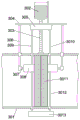
图2为本发明吹灰组件的结构示意图。Fig. 2 is a schematic structural view of the soot blowing assembly of the present invention.
具体实施方式Detailed ways
以下结合附图对本发明的具体实施方式作进一步详细说明。The specific implementation manners of the present invention will be described in further detail below in conjunction with the accompanying drawings.
由图1和图2给出,一种水泥生产用尾气处理再利用系统,回转窑1、分解窑7、预热器2、SCR反应器3、生料研磨设备11、袋式除尘器12和烟囱13,其特征在于,所述回转窑1和分解窑7均通过管道与预热器2之间连通,所述预热器2通过管道与SCR反应器3之间连通,所述生料研磨设备11与SCR反应器3之间设有余热锅炉9,所述余热锅炉9分别与生料研磨设备11和SCR反应器3之间通过管道连通,所述生料研磨设备11通过管道烟囱13连通,所述袋式除尘器12位于生料研磨设备11与烟囱13之间且袋式除尘器12的两端分别通过管道与生料研磨设备11与烟囱13之间连通,所述生料研磨设备11与余热锅炉9之间通过管道连通有分离器10,所述分离器10通过管道与SCR反应器3之间通过管道连通。As shown in Figure 1 and Figure 2, a tail gas treatment and reuse system for cement production, rotary kiln 1, decomposition kiln 7, preheater 2,
在水泥生产过程中产生NOx的来源主要有两个:在温度区间为500℃~1 500℃时,分解炉和回转窑1中产生燃料型NOx,大约占全部NOx 的75%~95%;温度>1 200℃时在回转窑1内生成热力型NOx,回转窑1和分解窑7产生的烟气通过预热器2对工序各个需要预热的设备进行预热,从而达到烟气降温的目的,当烟气到达SCR反应器3时的温度为320℃~340℃,氨逃逸量<1mg/m3(标),脱硝效率>80%,经过SCR反应器3的反应,将气体分解为氮气和水蒸气,然后混合气体通过锅炉预热的作用,对其余热进行吸收个重新的利用,然后混合气体通过分离器10,将混合气体分离成氮气和水蒸气,并且通过管道与SCR反应器3之间连通,氮气直接通入到SCR反应器3内部,氮气与烟气混合,初步的反应,减少烟气中混合气体的种类,便于SCR反应器3进行反应,而水蒸气通入到SCR反应器3内部能够对催化剂进行吹灰,进而避免需要重新准备压缩气体,降低了成本,减少资源的浪费,反应之后的气体进入生料研磨设备11烘干生料,温度降至110°C,然后经布袋除尘器后,由主风机送至烟囱13排放。最终排烟温度为90°C,含尘量18mgNm3,NOx浓度为36.5mg/Nm3,到了排放的标准。There are two main sources of NOx in the cement production process: when the temperature range is 500°C~1 500°C, fuel-type NOx is generated in the calciner and rotary kiln 1, accounting for about 75%~95% of the total NOx; When the temperature is higher than 1 200°C, thermal NOx is generated in the rotary kiln 1, and the flue gas produced by the rotary kiln 1 and the decomposition kiln 7 is preheated by the preheater 2 for each equipment that needs to be preheated in the process, so as to achieve the goal of flue gas cooling. Purpose, when the flue gas reaches the
所述分离器10与SCR反应器3连通的管道上串联有热交换器8,所述热交换器8通过管道分别与回转窑1和分解窑7之间连通,所述热交换器8通过管道与预热器2之间连通。The pipeline connecting the
经过余热锅炉9的气体的温度相对于SCR反应器3的反应温度低,为了避免通过分离器10之后的水蒸气和氮气在进入到SCR反应器3内时对催化反应产生影响,通过设置热交换器8,通过管道,将回转窑1和分解窑7中的一部分烟气通入到热交换器8内部,从而实现对水蒸气和氮气的升温,从而达到催化的最佳温度,进而提高对烟气的脱硝效果,并且热交换之后的烟气通过管道向预热器2流通,对其的热量进一步的吸收,避免了需要外加热源,降低了系统的使用成本和设备成本。The temperature of the gas passing through the
所述热交换器8与SCR反应器3之间设有氮气储存罐5和水蒸气储存罐6。A nitrogen storage tank 5 and a water vapor storage tank 6 are arranged between the
通过设置氮气储存罐5和水蒸气储存罐6,对分离之后的水蒸气和氮气进行储存,以便于对进入SCR反应器3内部的气体进行控制,避免对气体的浪费还能便于对系统整体进行控制。By setting the nitrogen storage tank 5 and the water vapor storage tank 6, the separated water vapor and nitrogen are stored, so as to control the gas entering the
所述氮气储存罐5和水蒸气储存罐6与SCR反应器3之间均设有高温风机4。A high-temperature fan 4 is arranged between the nitrogen storage tank 5 and the water vapor storage tank 6 and the
高温风机4能够适应高温工作,减少由于温度过高对风机造成损坏,从而减少系统使用时的成本。The high-temperature blower 4 can adapt to high-temperature work and reduce damage to the blower due to excessive temperature, thereby reducing the cost of the system in use.
所述SCR反应器3包括箱体301,所述箱体301内部固定有催化剂过滤板3011,所述催化剂过滤板3011的两侧均滑动配合有集尘箱308且所述两个集尘箱308朝向催化剂过滤板3011的一侧均设有开口,所述集尘箱308背离催化剂过滤板3011的一侧均设有导杆306,所述导杆306均与箱体301之间滑动配合,所述两个集尘箱308上均连通有第一喷气管309和第二喷气管3010,所述两个集尘箱308上均连通有收尘管3012,所述两个收尘管3012均与箱体301之间滑动配合且两个收尘管3012上固定有过滤器3013。The
现有的SCR反应器3在使用时每天需要对其进行多次停机的吹灰,从而降低了其生产效率,通过滑动安装集尘箱308,使用时能够通过两个喷气管推动集尘箱308的位置改变,集尘箱308在移动时,始终与催化剂过滤板3011之间紧密的接触,并且第一喷气管309对催化剂过滤板3011表面的积灰进行吹拂,而第二喷气管3010能够对催化剂过滤板3011反向进行吹灰,从而提高了吹灰的效率,进一步的降低积灰对催化效率产生的影响,吹灰之后的积灰通过收尘管3012对其进行吸取,从而避免其重新吸附在催化剂过滤板3011上,通过设置的过滤器3013,能够对积灰进行有效的过滤,避免对生产环境造成污染,通过两个喷气管对集尘箱308的位置进行调整,从而不影响催化剂过滤板3011的使用情况,提高了催化的效率,不会对生产效率造成影响。When the existing
所述第一喷气管309和第二喷气管3010上连通有脉冲器305,所述脉冲器305与水蒸气储存罐6之间连通。The first
通过设置脉冲器305,使用时,将水蒸气储存罐6内部的水蒸气进行间断式的抽取,并且在脉冲器305的作用下对催化剂过滤板3011进行间接性的吹灰,进一步的提高了吹灰的效果,进一步的提高装置的使用效果。By setting the
所述第一喷气管309和第二喷气管3010上均固定有支撑板304,所述箱体301上转动安装有螺杆303,所述螺杆303与支撑板304之间螺纹配合,且支撑板304上固定有驱动电机302,所述驱动电机302的输出端与螺杆303之间连接。Both the
驱动电机302采用伺服电机,使用时驱动电机302的转动带动支撑板304移动,从而实现带动集尘箱308的移动,从而实现不间断的对催化剂过滤板3011的清理,进一步的提高了装置的使用效果。The
所述两个导杆306与集尘箱308之间均固定有弹簧伸缩杆307。A spring
通过设置的弹簧伸缩杆307,使得两个集尘箱308能够始终与催化剂过滤板3011之间紧密的接触,进一步的提高装置的使用效果。Through the spring
本发明的有益效果:Beneficial effects of the present invention:
第一,能够对水泥生产时产生的烟气进行吸收,并且对烟气进行有效的脱硝,达到需要排放的标准,在进行脱销的时候,能够对催化之后的气体进行收集和重新的利用,减少需要外来气体的消耗,从而减少生产的成本,提高对资源的利用效率和效果。First, it can absorb the flue gas generated during cement production, and effectively denitrify the flue gas to meet the required emission standards. When it is out of stock, it can collect and reuse the catalyzed gas, reducing The consumption of external gas is required, thereby reducing the cost of production and improving the efficiency and effect of resource utilization.
第二,能够及时的对SCR反应器内部的催化剂进行吹灰和清理,从而提高了反应器的反应效率,同时避免需要停机对其进行吹灰,进一步的提高了生产效率。Second, the soot blowing and cleaning of the catalyst inside the SCR reactor can be performed in a timely manner, thereby improving the reaction efficiency of the reactor, while avoiding the need to stop the catalyst for soot blowing, and further improving the production efficiency.
第三,对SCR反应器的清理吹灰采用的气体为反应之后的气体,从而进一步的减少了资源的浪费,提高了对资源的利用效率,降低系统的使用成本。Third, the gas used for cleaning and soot blowing of the SCR reactor is the gas after the reaction, thereby further reducing the waste of resources, improving the utilization efficiency of resources, and reducing the use cost of the system.
以上所述的实施例并非对本发明的范围进行限定,在不脱离本发明设计构思的前提下,本领域所属技术人员对本发明的技术方案作出的各种变形和改进,均应纳入本发明的权利要求书确定的保护范围内。The above-described embodiments do not limit the scope of the present invention. Without departing from the design concept of the present invention, various modifications and improvements made by those skilled in the art to the technical solution of the present invention shall be included in the rights of the present invention. within the scope of protection specified in the requirements.
Claims (5)
Priority Applications (1)
| Application Number | Priority Date | Filing Date | Title |
|---|---|---|---|
| CN202110551457.1A CN113217935B (en) | 2021-05-20 | 2021-05-20 | Tail gas treatment recycling system for cement production |
Applications Claiming Priority (1)
| Application Number | Priority Date | Filing Date | Title |
|---|---|---|---|
| CN202110551457.1A CN113217935B (en) | 2021-05-20 | 2021-05-20 | Tail gas treatment recycling system for cement production |
Publications (2)
| Publication Number | Publication Date |
|---|---|
| CN113217935A CN113217935A (en) | 2021-08-06 |
| CN113217935B true CN113217935B (en) | 2023-05-02 |
Family
ID=77093282
Family Applications (1)
| Application Number | Title | Priority Date | Filing Date |
|---|---|---|---|
| CN202110551457.1A Active CN113217935B (en) | 2021-05-20 | 2021-05-20 | Tail gas treatment recycling system for cement production |
Country Status (1)
| Country | Link |
|---|---|
| CN (1) | CN113217935B (en) |
Family Cites Families (6)
| Publication number | Priority date | Publication date | Assignee | Title |
|---|---|---|---|---|
| CN208660780U (en) * | 2018-06-07 | 2019-03-29 | 中国科学院过程工程研究所 | A kind of SCR denitration system suitable for the high-alkali flue gas of the high dirt of cement kiln tail |
| CN109966812A (en) * | 2019-03-29 | 2019-07-05 | 北京国电龙源环保工程有限公司 | A kind of cement kiln end denitrating flue gas and system, the process of waste heat recycling |
| CN110314543A (en) * | 2019-08-02 | 2019-10-11 | 陕西大秦环境科技有限公司 | Dirt arrangement SCR denitration device and technique in a kind of cement kiln |
| CN110455091A (en) * | 2019-09-16 | 2019-11-15 | 中国科学院过程工程研究所 | A SCR denitrification system for cement flue gas |
| CN110652870A (en) * | 2019-10-24 | 2020-01-07 | 周锦波 | SCR industrial flue gas denitration equipment |
| CN213101604U (en) * | 2020-08-26 | 2021-05-04 | 天津泰达环保有限公司 | Denitration device for flue gas treatment |
-
2021
- 2021-05-20 CN CN202110551457.1A patent/CN113217935B/en active Active
Also Published As
| Publication number | Publication date |
|---|---|
| CN113217935A (en) | 2021-08-06 |
Similar Documents
| Publication | Publication Date | Title |
|---|---|---|
| CN205145971U (en) | Coke oven flue gas desulfurization denitration dust removal integration system | |
| CN104100964A (en) | Synergistic removal system and method for realizing ultra-low emission of multiple pollutants of smoke of thermal power plant | |
| CN105944564A (en) | Coke oven flue gas waste heat recovery and utilization, desulfurization and denitrification integrated system and method | |
| CN108579369B (en) | A coke oven flue gas multi-pollutant collaborative treatment system and method | |
| CN110437849B (en) | Dry quenching and coke oven flue gas combined purification process and system | |
| CN109966812A (en) | A kind of cement kiln end denitrating flue gas and system, the process of waste heat recycling | |
| CN110624384A (en) | Purification treatment method and purification treatment device for waste incineration flue gas | |
| CN110314543A (en) | Dirt arrangement SCR denitration device and technique in a kind of cement kiln | |
| CN110075681B (en) | A dry desulfurization and denitrification device and method suitable for cement kiln flue gas | |
| CN110484283B (en) | Comprehensive recovery process and system for coking waste heat | |
| CN105214478A (en) | The integral process of a kind of coke oven flue exhuast gas desulfurization denitration and waste heat recovery | |
| CN111346605B (en) | A comprehensive pollution control system and method suitable for large coal-fired power plants | |
| CN202942800U (en) | Desulfurization and denitrification combined system for sintering flue gas | |
| CN102302892A (en) | Method and system for treating flue gas from a high temperature waste incinerator using a double effect reactor | |
| CN105169943A (en) | Integrated system for coke oven flue gas desulfurization and denitrification and waste heat recovery | |
| CN203494378U (en) | SCR (Selective Catalytic Reduction) denitration device for controlling NOx of rotary cement kiln | |
| CN103706239B (en) | Based on the low temperature rotary generating plant flue gas denitrating system of adsorption technology | |
| CN205412681U (en) | Tail gas desulfurization , denitration, dust removal integration treatment device | |
| WO2020191915A1 (en) | Cement kiln flue gas denitration, demercuration, and desulphurisation system and method | |
| CN108543419A (en) | A kind of refuse burning system | |
| CN108704464B (en) | A sintering flue gas desulfurization, denitrification and flue gas whitening comprehensive treatment system and process | |
| CN102755821A (en) | Carbon calcining furnace waste gas desulfurizing and dust-removing method and device | |
| CN204891590U (en) | Energy -efficient deNOx systems of domestic waste power plant | |
| CN210855981U (en) | Dry quenching coke and coke oven flue gas combined purification system | |
| CN100431669C (en) | Method for treating SO2 in coal firing smoke by red mud |
Legal Events
| Date | Code | Title | Description |
|---|---|---|---|
| PB01 | Publication | ||
| PB01 | Publication | ||
| SE01 | Entry into force of request for substantive examination | ||
| SE01 | Entry into force of request for substantive examination | ||
| GR01 | Patent grant | ||
| GR01 | Patent grant |