CN113210945B - Middle assembly welding device, plane segmentation assembly line and middle assembly welding method - Google Patents
Middle assembly welding device, plane segmentation assembly line and middle assembly welding method Download PDFInfo
- Publication number
- CN113210945B CN113210945B CN202110558338.9A CN202110558338A CN113210945B CN 113210945 B CN113210945 B CN 113210945B CN 202110558338 A CN202110558338 A CN 202110558338A CN 113210945 B CN113210945 B CN 113210945B
- Authority
- CN
- China
- Prior art keywords
- welding
- assembly
- along
- robot
- frame
- Prior art date
- Legal status (The legal status is an assumption and is not a legal conclusion. Google has not performed a legal analysis and makes no representation as to the accuracy of the status listed.)
- Active
Links
Images


Classifications
-
- B—PERFORMING OPERATIONS; TRANSPORTING
- B23—MACHINE TOOLS; METAL-WORKING NOT OTHERWISE PROVIDED FOR
- B23K—SOLDERING OR UNSOLDERING; WELDING; CLADDING OR PLATING BY SOLDERING OR WELDING; CUTTING BY APPLYING HEAT LOCALLY, e.g. FLAME CUTTING; WORKING BY LASER BEAM
- B23K37/00—Auxiliary devices or processes, not specially adapted for a procedure covered by only one of the other main groups of this subclass
-
- B—PERFORMING OPERATIONS; TRANSPORTING
- B23—MACHINE TOOLS; METAL-WORKING NOT OTHERWISE PROVIDED FOR
- B23K—SOLDERING OR UNSOLDERING; WELDING; CLADDING OR PLATING BY SOLDERING OR WELDING; CUTTING BY APPLYING HEAT LOCALLY, e.g. FLAME CUTTING; WORKING BY LASER BEAM
- B23K37/00—Auxiliary devices or processes, not specially adapted for a procedure covered by only one of the other main groups of this subclass
- B23K37/02—Carriages for supporting the welding or cutting element
- B23K37/0211—Carriages for supporting the welding or cutting element travelling on a guide member, e.g. rail, track
-
- B—PERFORMING OPERATIONS; TRANSPORTING
- B23—MACHINE TOOLS; METAL-WORKING NOT OTHERWISE PROVIDED FOR
- B23K—SOLDERING OR UNSOLDERING; WELDING; CLADDING OR PLATING BY SOLDERING OR WELDING; CUTTING BY APPLYING HEAT LOCALLY, e.g. FLAME CUTTING; WORKING BY LASER BEAM
- B23K37/00—Auxiliary devices or processes, not specially adapted for a procedure covered by only one of the other main groups of this subclass
- B23K37/04—Auxiliary devices or processes, not specially adapted for a procedure covered by only one of the other main groups of this subclass for holding or positioning work
- B23K37/0426—Fixtures for other work
- B23K37/0435—Clamps
- B23K37/0443—Jigs
Landscapes
- Physics & Mathematics (AREA)
- Optics & Photonics (AREA)
- Engineering & Computer Science (AREA)
- Mechanical Engineering (AREA)
- Butt Welding And Welding Of Specific Article (AREA)
Abstract
本发明属于船舶技术领域,具体公开了一种中组立焊接装置、平面分段流水线及中组立焊接方法。其中,中组立焊接装置,包括:轨道,沿Y方向延伸,且沿X方向间隔设置有两个;焊接工装,沿Y方向间隔设置有至少两个,每个焊接工装均包括门架和焊接机器人,焊接机器人沿X方向间隔设置有至少两个,且每个焊接机器人均能够在门架上沿X方向、Y方向及Z方向滑动。平面分段流水线包括上述的中组立焊接装置。中组立焊接方法使用如上的中组立焊接装置进行中组立构件的焊接。本发明公开的中组立焊接装置、平面分段流水线及中组立焊接方法能够提高中组立构件的焊接效率和焊接质量。
The invention belongs to the technical field of ships, and specifically discloses a center group vertical welding device, a plane segmented assembly line and a center group vertical welding method. Among them, the vertical welding device in the middle group includes: rails extending along the Y direction, and two are arranged at intervals along the X direction; welding fixtures are arranged at least two at intervals along the Y direction, and each welding fixture includes a door frame and a welding Robots, at least two welding robots are arranged at intervals along the X direction, and each welding robot can slide on the gantry along the X direction, the Y direction and the Z direction. The plane segmented assembly line includes the above-mentioned intermediate assembly welding device. The middle group vertical welding method uses the above middle group vertical welding device to perform welding of the middle group vertical member. The center group vertical welding device, the plane segmented assembly line and the center group vertical welding method disclosed by the invention can improve the welding efficiency and welding quality of the center group vertical components.
Description
技术领域technical field
本发明涉及船舶技术领域,尤其涉及一种中组立焊接装置、平面分段流水线及中组立焊接方法。The invention relates to the technical field of ships, in particular to a center-set welding device, a plane segmented assembly line and a center-set welding method.
背景技术Background technique
船舶分段或钢结构制作过程中,一般分为多个中组立进行加工,然后拼装成完整分段,且对于船厂来说,平直区域的中组立一般都安排在平面分段流水线进行制作,以形成节拍式生产。In the process of ship segmentation or steel structure manufacturing, it is generally divided into multiple intermediate assemblies for processing, and then assembled into complete sections, and for shipyards, intermediate assemblies in flat areas are generally arranged on the plane segmented assembly line production to form beat production.
在平面分段流水线上,拼板工位、纵骨焊接工位均配置了高效焊接设备进行自动化焊接,而中组立的肋板焊接工作安排在肋板焊接工位上进行。现有的中组立的肋板焊接,通常采用人工手动进行,焊接效率低,且焊接质量与焊接工人的技术水平有较大关系,焊缝成型相对较差且不稳定,难以保证中组立的加工质量和加工一致性,且会影响平面分段流水线的整体生产节拍。On the plane segmented assembly line, the jigsaw station and the longitudinal welding station are equipped with high-efficiency welding equipment for automatic welding, while the rib welding work in the middle group is arranged at the rib welding station. The existing rib plate welding of the center group is usually carried out manually, the welding efficiency is low, and the welding quality has a great relationship with the technical level of the welder, the weld shape is relatively poor and unstable, and it is difficult to ensure the center group The processing quality and consistency of processing, and will affect the overall production beat of the flat segmented assembly line.
发明内容Contents of the invention
本发明的一个目的在于提供一种中组立焊接装置,以实现对中组立构件上的肋板的自动焊接,提高焊接质量、焊接效率和焊接自动化。An object of the present invention is to provide a centering vertical welding device to realize automatic welding of ribs on centering vertical members, improve welding quality, welding efficiency and welding automation.
本发明的另一个目的在于提供一种平面分段流水线,以提高平面分段流水线的生产效率和生产自动化。Another object of the present invention is to provide a plane segmentation assembly line to improve the production efficiency and production automation of the plane segmentation assembly line.
本发明的又一个目的在于提供一种中组立焊接方法,以提高中组立构件的焊接效率、焊接质量和焊接自动化。Yet another object of the present invention is to provide a method for welding vertical components, so as to improve the welding efficiency, welding quality and automation of vertical components.
为实现上述目的,本发明采用下述技术方案:To achieve the above object, the present invention adopts the following technical solutions:
一种中组立焊接装置,包括:A medium assembly welding device, comprising:
轨道,沿Y方向延伸,且沿X方向间隔设置有两个;The track extends along the Y direction, and there are two tracks arranged at intervals along the X direction;
焊接工装,沿Y方向间隔设置有至少两个,每个焊接工装均包括门架和焊接机器人,门架跨设在两个所述轨道上且两个下端分别与对应的轨道滑动连接,焊接机器人沿X方向间隔设置有至少两个,且每个所述焊接机器人均能够在所述门架上沿所述X方向、所述Y方向及Z方向滑动。There are at least two welding fixtures at intervals along the Y direction. Each welding fixture includes a gantry and a welding robot. At least two welding robots are arranged at intervals along the X direction, and each of the welding robots can slide along the X direction, the Y direction and the Z direction on the portal frame.
作为一种中组立焊接装置的优选技术方案,所述门架包括沿X方向相对且间隔设置的两个纵支撑架,每个所述纵支撑架均包括沿Y方向相对且间隔设置的两个立柱以及连接于两个所述立柱下端之间的底梁,所述底梁与所述轨道滑动连接;As a preferred technical solution of the middle assembly welding device, the gantry includes two vertical support frames opposite and spaced along the X direction, and each of the vertical support frames includes two opposite and spaced vertical support frames along the Y direction. a column and a bottom beam connected between the lower ends of the two columns, the bottom beam is slidingly connected to the track;
两个所述纵支撑架的顶端连接有横支撑架,所述横支撑架为矩形框架结构,所述焊接机器人位于所述矩形框架结构的内侧。The top ends of the two vertical support frames are connected with a horizontal support frame, the horizontal support frame is a rectangular frame structure, and the welding robot is located inside the rectangular frame structure.
作为一种中组立焊接装置的优选技术方案,每个所述焊接机器人均通过滑动机构与所述门架滑动连接,所述滑动机构包括:As a preferred technical solution of the middle assembly welding device, each of the welding robots is slidingly connected to the door frame through a sliding mechanism, and the sliding mechanism includes:
滑动梁,沿所述Y方向设置,且两端分别与所述横支撑架的两个顶横梁滑动连接;The sliding beam is arranged along the Y direction, and the two ends are slidingly connected to the two top beams of the horizontal support frame;
X向驱动组件,用于驱动所述滑动梁沿所述X方向滑动;an X-direction drive assembly, configured to drive the sliding beam to slide along the X direction;
安装架,滑动设置于所述滑动梁上,所述焊接机器人滑动设置于所述安装架上;A mounting frame is slidably arranged on the sliding beam, and the welding robot is slidably arranged on the mounting frame;
Y向驱动组件,用于驱动所述安装架沿所述Y方向滑动;a Y-direction drive assembly, configured to drive the installation frame to slide along the Y direction;
Z向驱动组件,用于驱动所述焊接机器人相对所述安装架沿Z方向滑动。The Z-direction driving assembly is used to drive the welding robot to slide relative to the installation frame along the Z direction.
作为一种中组立焊接装置的优选技术方案,所述安装架包括底框部和垂直围设于所述底框部周缘处的挡框部,所述挡框部与所述底框部合围形成有开口朝向所述焊接机器人的容置空间,所述容置空间中设置有焊接控制箱,所述焊接控制箱与所述X向驱动组件、所述Y向驱动组件、所述Z向驱动组件及所述焊接机器人电性连接。As a preferred technical solution of the middle assembly welding device, the installation frame includes a bottom frame part and a stop frame part vertically surrounding the periphery of the bottom frame part, and the stop frame part is surrounded by the bottom frame part An accommodating space with an opening facing the welding robot is formed, a welding control box is arranged in the accommodating space, and the welding control box is connected with the X-direction drive assembly, the Y-direction drive assembly, and the Z-direction drive The components and the welding robot are electrically connected.
一种平面分段流水线,包括沿流水线方向依次设置的拼板工位、纵骨焊接工位及肋板焊接工位,所述肋板焊接工位上设置有如上所述的中组立焊接装置。A plane segmented assembly line, comprising a jigsaw station, a longitudinal bone welding station, and a rib plate welding station arranged sequentially along the line direction, and the rib plate welding station is provided with the above-mentioned intermediate assembly welding device .
一种中组立焊接方法,使用如上所述的中组立焊接装置进行中组立构件的焊接,并包括如下步骤:A kind of vertical welding method of middle group, uses the vertical welding device of middle group as above to carry out the welding of vertical member of middle group, and comprises the following steps:
构建中组立构件的三维仿真模型;Construct the 3D simulation model of the vertical components;
仿真生成焊接程序;Simulation generates welding program;
将拼装完成的所述中组立构件输送至所述门架下方;Transporting the assembled vertical member to the bottom of the door frame;
对所述中组立构件进行位置标定;Carrying out position calibration on the middle assembly vertical member;
自动焊接,若干个所述焊接机器人根据所述位置标定及所述焊接程序对所述中组立构件中的待焊接焊缝同步进行自动焊接。Automatic welding, several welding robots perform automatic welding synchronously on the seams to be welded in the intermediate component according to the position calibration and the welding program.
作为一种中组立焊接方法的优选技术方案,在所述自动焊接之前及所述位置标定之后,还包括:根据所述中组立构件在所述Y方向的尺寸及所述位置标定,调节相邻两个所述焊接工装的位置。As a preferred technical solution of the middle assembly welding method, before the automatic welding and after the position calibration, it also includes: according to the size of the middle assembly member in the Y direction and the position calibration, adjusting The positions of two adjacent welding fixtures.
作为一种中组立焊接方法的优选技术方案,所述仿真生成焊接程序包括:As a preferred technical solution of a neutral assembly welding method, the simulation generating welding program includes:
基于所述三维仿真模型,确定焊缝数量、焊缝位置及每个焊缝的特征参数;Based on the three-dimensional simulation model, determine the number of welds, the position of the welds and the characteristic parameters of each weld;
根据所述焊缝数量、所述焊缝位置及所述焊接机器人的数量及分布,确认每个焊接机器人的焊接区域;Confirming the welding area of each welding robot according to the number of welds, the positions of the welds, and the number and distribution of the welding robots;
基于所述焊接区域,对每个所述焊接机器人进行焊接路径规划。Based on the welding area, a welding path planning is performed for each of the welding robots.
作为一种中组立焊接方法的优选技术方案,在焊接机器人进行焊接时,数据采集模块自动监控并采集焊接数据;As an optimal technical solution of a neutral welding method, when the welding robot is welding, the data acquisition module automatically monitors and collects welding data;
在所述自动焊接完毕后,将所述焊接数据存放至车间管控系统的数据库中。After the automatic welding is completed, the welding data is stored in the database of the workshop control system.
作为一种中组立焊接方法的优选技术方案,所述中组立焊接方法还包括步骤:As a preferred technical scheme of a middle-group welding method, the middle-group welding method also includes the steps of:
自动清枪,在所述焊接机器人完成若干焊缝的焊接后,所述焊接机器人按照设定焊接程序完成焊接枪头的清枪工作;Automatic gun cleaning, after the welding robot completes the welding of several weld seams, the welding robot completes the cleaning work of the welding gun head according to the set welding procedure;
在所述自动清枪操作完毕后,所述焊接机器人基于所述焊接程序,自动寻找下一条焊缝并焊接。After the operation of the automatic torch cleaning is completed, the welding robot automatically finds and welds the next welding seam based on the welding program.
本发明的有益效果在于:The beneficial effects of the present invention are:
本发明提供的中组立焊接装置,当需要对中组立构件进行焊接时,将中组立构件输送至两个轨道之间且位于门架的下方,由于焊接机器人能够沿X、Y方向和Z方向滑动,从而能够实现对中组立构件上的纵向焊缝和竖向焊缝的自动化焊接,提高中组立构件上肋板的焊接效率和焊接质量;且通过沿Y方向间隔设置两个以上能够在轨道上滑动的焊接工装,且在每个焊接工装上沿X方向间隔设置两个以上的焊接机器人,能够实现多个焊接机器人对同一中组立构件的同时焊接,进一步地提高焊接效率;且由于设置有两个以上焊接工装,能够在中组立焊接过程中,减少或避免焊接工装在轨道上的滑动,提高焊接效率。The middle group vertical welding device provided by the present invention, when the middle group vertical member needs to be welded, the middle group vertical member is transported between the two rails and located under the door frame, because the welding robot can move along the X, Y directions and Sliding in the Z direction, so that the automatic welding of the longitudinal weld and the vertical weld on the centered vertical member can be realized, and the welding efficiency and welding quality of the rib plate on the middle vertical member can be improved; and by setting two The above-mentioned welding tool that can slide on the track, and more than two welding robots are arranged at intervals along the X direction on each welding tool, can realize the simultaneous welding of multiple welding robots on the same vertical component, and further improve the welding efficiency ; and because more than two welding fixtures are provided, the sliding of the welding fixtures on the track can be reduced or avoided during the middle assembly welding process, and the welding efficiency can be improved.
本发明提供的平面分段流水线,通过在肋板焊接工位上设置上述的中组立焊接装置对肋板进行焊接,能够提高平面分段流水线的生产效率、生产自动化和生产质量。The planar segmented assembly line provided by the present invention can improve the production efficiency, production automation and production quality of the planar segmented assembly line by installing the above-mentioned intermediate assembly welding device on the rib plate welding station to weld the ribs.
本发明提供的中组立焊接方法,通过采用上述的中组立焊接装置对中组立上的肋板进行焊接,能够提高肋板焊接效率、焊接质量和焊接自动化。In the method for welding the center stand provided by the present invention, by using the above-mentioned center stand welding device to weld the ribs on the center stand, the rib plate welding efficiency, welding quality and welding automation can be improved.
附图说明Description of drawings
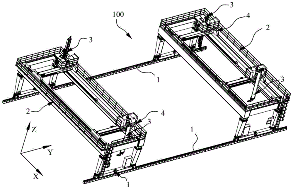
图1是本发明实施例一提供的中组立焊接装置的结构示意图;Fig. 1 is a schematic structural view of a middle assembly welding device provided by Embodiment 1 of the present invention;
图2是本发明实施例二中提供的中组立构件的结构示意图;Fig. 2 is a schematic structural view of the middle assembly vertical member provided in the second embodiment of the present invention;
图3是图2中I处的局部放大图;Fig. 3 is the partial enlarged view of I place in Fig. 2;
图4是本发明实施例一提供的中组立焊接装置的部分结构示意图;Fig. 4 is a partial structural schematic diagram of the middle assembly welding device provided by Embodiment 1 of the present invention;
图5是图4中J处的局部放大图;Fig. 5 is a partial enlarged view of J in Fig. 4;
图6是本发明实施例二提供的中组立焊接方法的流程图。Fig. 6 is a flow chart of the middle assembly welding method provided by the second embodiment of the present invention.
图中标记如下:The markings in the figure are as follows:
100、中组立焊接装置;200、中组立构件;201、外板;202、外底纵骨;203、纵桁板;204、纵肋板;205、横肋板;206、竖向焊缝;207、纵向焊缝;208、纵向加强筋;209、横向加强筋板;100. Middle group vertical welding device; 200. Middle group vertical member; 201. Outer plate; 202. Outer bottom longitudinal; 203. Longitudinal girder plate; 204. Longitudinal rib; 205. Transverse rib; 206. Vertical welding Seam; 207, longitudinal weld; 208, longitudinal rib; 209, transverse rib plate;
1、轨道;11、基座;12、导轨;2、门架;21、纵支撑架;211、立柱;212、底梁;22、横支撑架;221、顶横梁;222、顶纵梁;23、围栏;24、攀登梯;25、护栏;3、焊接机器人;31、悬臂梁;32、焊接机械手;4、滑动机构;41、滑动梁;411、主梁部;412、滑动安装部;42、安装架;421、底框部;422、挡框部;423、安装框部;43、弹性缓冲件;5、门架驱动机构;51、门架驱动电机;52、齿条;53、电控箱;6、导向滚轮;7、控制面板;8、焊接控制箱。1. Track; 11. Base; 12. Guide rail; 2. Door frame; 21. Vertical support frame; 211. Column; 212. Bottom beam; 22. Horizontal support frame; 221. Top beam; 222. Top longitudinal beam; 23. Fence; 24. Climbing ladder; 25. Guardrail; 3. Welding robot; 31. Cantilever beam; 32. Welding manipulator; 4. Sliding mechanism; 41. Sliding beam; 411. Main beam part; 412. Sliding installation part; 42. Mounting frame; 421. Bottom frame part; 422. Block frame part; 423. Installation frame part; 43. Elastic buffer; 5. Mast drive mechanism; 51. Mast drive motor; 52. Rack; 53 Electric control box; 6. Guide roller; 7. Control panel; 8. Welding control box.
具体实施方式Detailed ways
下面结合附图和实施例对本发明作进一步的详细说明。可以理解的是,此处所描述的具体实施例仅仅用于解释本发明,而非对本发明的限定。另外还需要说明的是,为了便于描述,附图中仅示出了与本发明相关的部分而非全部结构。The present invention will be further described in detail below in conjunction with the accompanying drawings and embodiments. It should be understood that the specific embodiments described here are only used to explain the present invention, but not to limit the present invention. In addition, it should be noted that, for the convenience of description, only some structures related to the present invention are shown in the drawings but not all structures.
在本发明的描述中,除非另有明确的规定和限定,术语“相连”、“连接”、“固定”应做广义理解,例如,可以是固定连接,也可以是可拆卸连接,或成一体;可以是机械连接,也可以是电连接;可以是直接相连,也可以通过中间媒介间接相连,可以是两个元件内部的连通或两个元件的相互作用关系。对于本领域的普通技术人员而言,可以具体情况理解上述术语在本发明中的具体含义。In the description of the present invention, unless otherwise clearly specified and limited, the terms "connected", "connected" and "fixed" should be understood in a broad sense, for example, it can be a fixed connection, a detachable connection, or an integrated ; It can be a mechanical connection or an electrical connection; it can be a direct connection or an indirect connection through an intermediary, and it can be the internal communication of two components or the interaction relationship between two components. Those of ordinary skill in the art can understand the specific meanings of the above terms in the present invention in specific situations.
在本发明中,除非另有明确的规定和限定,第一特征在第二特征之“上”或之“下”可以包括第一和第二特征直接接触,也可以包括第一和第二特征不是直接接触而是通过它们之间的另外的特征接触。而且,第一特征在第二特征“之上”、“上方”和“上面”包括第一特征在第二特征正上方和斜上方,或仅仅表示第一特征水平高度高于第二特征。第一特征在第二特征“之下”、“下方”和“下面”包括第一特征在第二特征正下方和斜下方,或仅仅表示第一特征水平高度小于第二特征。In the present invention, unless otherwise clearly specified and limited, a first feature being "on" or "under" a second feature may include direct contact between the first and second features, and may also include the first and second features Not in direct contact but through another characteristic contact between them. Moreover, "above", "above" and "above" the first feature on the second feature include that the first feature is directly above and obliquely above the second feature, or simply means that the first feature is horizontally higher than the second feature. "Below", "beneath" and "under" the first feature to the second feature include that the first feature is directly below and obliquely below the second feature, or simply means that the first feature has a lower level than the second feature.
在本实施例的描述中,术语“上”、“下”、“右”、等方位或位置关系为基于附图所示的方位或位置关系,仅是为了便于描述和简化操作,而不是指示或暗示所指的装置或元件必须具有特定的方位、以特定的方位构造和操作,因此不能理解为对本发明的限制。此外,术语“第一”、“第二”仅仅用于在描述上加以区分,并没有特殊的含义。In the description of this embodiment, the terms "up", "down", "right", and other orientations or positional relationships are based on the orientations or positional relationships shown in the drawings, and are only for the convenience of description and simplification of operations, rather than indicating Or imply that the device or element referred to must have a specific orientation, be constructed and operate in a specific orientation, and therefore should not be construed as limiting the invention. In addition, the terms "first" and "second" are only used to distinguish in description, and have no special meaning.
实施例一Embodiment one
如图1所示,本实施例提供了一种中组立焊接装置100,其可应用于船舶生产制造领域,用于对船舶分段生产中的中组立构件进行自动化焊接,且能够将中组立构件的焊接工序较好地融入平面分段流水线中,提高平面分段流水线的生产效率,保证平面分段流水线的生产节拍。As shown in Fig. 1, the present embodiment provides a center assembly
作为示例,图2提供了一种船舶生产中的典型中组立构件200,其包括外板次级中组立、纵桁小组立、纵肋板204及横肋板205等。其中,外板次级中组立包括沿XY平面设置的外板201及沿X方向间隔设置在外板201上的外底纵骨202,外板201由多个板拼接形成,且外板201在平面分段流水线的拼板工位被拼装焊接。外底纵骨202沿Y方向延伸,且外底纵骨202在外板201上的拼装及焊接在平面分段流水线的纵骨焊接工位进行;纵桁小组立包括沿Y方向延伸的纵桁板203及设置在纵桁板203上的纵向加强筋208及横向加强筋板209,纵桁板203可由多个沿Y方向拼装的矩形板焊接形成;纵肋板204沿Y方向延伸,并沿X方向间隔设置有至少两个,相邻两个纵肋板204之间设置有纵桁小组立;横肋板205沿Y方向间隔设置有多个,且连接于相邻设置的纵肋板204和纵桁板203之间,且每个横肋板205均连接于纵桁板203未设置有纵向加强筋208的一面。As an example, Fig. 2 provides a typical
如图2和3所示,纵肋板204与外板201拼接形成有沿Y方向延伸的纵向焊缝207,横肋板205与纵肋板204的拼接处以及横肋板205与纵桁板203的拼接处形成沿Z方向延伸的竖向焊缝206,该纵向焊缝207与竖向焊缝206采用本实施例提供的中组立焊接装置100进行焊接完成。As shown in Figures 2 and 3, the
值得说明的是,图2提供的中组立构件200的结构为示例性结构,本实施例提供的中组立焊接装置100还能对其他结构形式的中组立构件200进行焊接,如对不存在纵桁小组或者纵桁小组排布结构与图2中不同的中组立结构,或者对不存在横肋板的中组立结构等,只要是肋板与外板形成有纵向焊缝或者横向焊缝的结构即可,本发明对中组立构件200的具体结构不做进一步限制。It is worth noting that the structure of the
如图1、图4及图5所示,中组立焊接装置100包括轨道组件及焊接工装。其中,轨道组件包括沿X方向间隔设置的两个轨道1,每个轨道1沿Y方向延伸;焊接工装沿Y方向间隔设置有至少两个,每个焊接工装均包括门架2及焊接机器人3,门架2跨设在两个轨道1上且两个下端分别与对应的轨道1滑动连接;焊接机器人3沿X方向间隔设置有至少两个,且每个焊接机器人3均能够在门架2上沿X方向、Y方向及Z方向滑动。As shown in FIG. 1 , FIG. 4 and FIG. 5 , the
本实施例提供的中组立焊接装置100,当需要对中组立构件200进行焊接时,将中组立构件200输送至两个轨道1之间且位于门架2的下方,由于焊接机器人3能够沿X、Y方向和Z方向滑动,从而能够实现对中组立构件200上的纵向焊缝207和竖向焊缝206的自动化焊接,提高中组立构件200上肋板(包括横肋板205和纵肋板204)的焊接效率和焊接质量;且通过沿Y方向间隔设置两个以上能够在轨道1上滑动的焊接工装,且在每个焊接工装上沿X方向间隔设置两个以上的焊接机器人3,能够实现多个焊接机器人3对同一中组立构件200的同时焊接,进一步地提高焊接效率;且由于设置有两个以上焊接工装,能够在中组立构件200焊接过程中,减少或避免焊接工装在轨道1上的滑动,提高焊接效率。The middle group
在本实施例中,焊接工装设置有两个,每个焊接工装上均设置有两个焊接机器人3。在其他实施例中,焊接工装也可以多于两个,或者,同一焊接工装上的焊接机器人3也可以多于两个,焊接工装的个数以及每个焊接工装上的焊接机器人3的个数可以根据需求进行设置,如可以根据中组立构件200上的纵肋板204的个数确定每个焊接工装上的焊接机器人3的个数。In this embodiment, there are two welding fixtures, and each welding fixture is provided with two welding robots 3 . In other embodiments, the welding tool can also be more than two, or the welding robot 3 on the same welding tool can also be more than two, the number of welding tools and the number of welding robots 3 on each welding tool It can be set according to requirements, for example, the number of welding robots 3 on each welding tool can be determined according to the number of
具体地,门架2包括沿X方向间隔设置的两个纵支撑架21和连接于两个纵支撑架21顶端之间的横支撑架22,每个纵支撑架21的下端均滑动设置于对应的轨道1上。纵支撑架21包括沿Y方向间隔设置的两个立柱211和连接于两个立柱211下端之间的底梁212,底梁212与立柱211的下端焊接,且底梁212与轨道1滑动连接。Specifically, the
优选地,为提高门架2的运行平稳性,轨道1与底梁212之间设置有纵向导向组件。在本实施例中,纵向导向组件包括导向滚轮6,底梁212的端部连接有安装板,导向滚轮6转动安装于安装板上,且导向滚轮6的转动轴向竖直设置,导向滚轮6与轨道1的侧壁滚动连接。导向滚轮6于轨道1的相对两侧各设置有一个。Preferably, in order to improve the running stability of the
通过设置导向滚轮6,能够在实现底梁212的运动导向的同时,还能够降低底梁212移动时的摩擦。在其他实施例中,还可以在底梁212上连接与轨道1滑动配合的滑块进行滑动导向。进一步地,纵向导向组件于底梁212的两端各设置一组,以进一步地提高导向稳定性和门架2的移动可靠性。By arranging the
轨道1优选包括铺设在地面上的基座11和可拆卸设置在基座11上表面的导轨12,导向滚轮6位于基座11的上方且与导轨12的侧壁滑动连接。通过设置基座11和导轨12,能够提高轨道1的整体承载能力,且方便加工和组装。The track 1 preferably includes a base 11 laid on the ground and a
为实现门架2在轨道1上的自动移动,中组立焊接装置100还包括门架驱动机构5,门架驱动机构5用于驱动门架2沿Y方向移动。在本实施例中,门架驱动机构5对应每个纵支撑架21各设置有一个,以降低每个门架驱动机构5所需的驱动力,同时避免在两个轨道1之间设置同步传动结构。In order to realize the automatic movement of the
优选地,门架驱动机构5包括门架驱动电机51、与门架驱动电机51的输出轴连接的主动齿轮以及铺设在导轨12一侧的齿条52,门架驱动电机51安装于底梁212上,其输出轴沿Z方向设置,主动齿轮与齿条52啮合。即,本实施例提供的门架驱动机构5,通过门架驱动电机51带动主动齿轮转动,从而实现主动齿轮沿齿条52移动,即实现门架2沿Y方向移动。Preferably, the gantry driving mechanism 5 includes a
进一步地,底梁212的中部凹设有安装槽,门架驱动电机51安装于安装槽中,能够减少门架驱动电机51的外露,为门架驱动电机51提供保护。门架驱动电机51与主动齿轮之间连接有减速器,用于降低底梁212的运行速度,增大传递的扭矩。底梁212上还安装有电控箱53,电控箱53与门架驱动电机51电性连接,以控制门架驱动电机51的运行。Furthermore, the middle part of the
可以理解的是,还可以采用现有其它门架驱动机构5的结构形式实现门架2沿Y方向的移动,如驱动电机配合丝杠螺母机构、驱动电机配合链轮链条机构或者驱动电机配合皮带传动机构等,本发明对此不做具体限制。It can be understood that the movement of the
横支撑架22为矩形框架结构,焊接机器人3位于矩形框架结构的内侧,且能够在横支撑架22上沿X方向、Y方向及Z方向滑动。具体地,横支撑架22包括沿X方向相对且间隔设置的两个顶纵梁222以及沿Y方向相对且间隔设置的两个顶横梁221,顶纵梁222沿Y方向延伸,顶横梁221沿X方向延伸,且顶纵梁222的两端分别与两个顶横梁221连接,顶横梁221的两端分别与两个立柱211的顶端连接。顶横梁221与顶纵梁222之间的连接以及顶纵梁222与立柱211之间的连接均优选采用焊接,以提高门架2的结构稳定性。两个顶横梁221之间的间距小于两个顶纵梁222之间的间距。The
为方便焊接机器人3在门架2上的拆装和维修,门架2于其中一立柱211的外侧还设置有竖直的攀登梯24,攀登梯24的上部围设有防止工作人员摔落的护栏25。进一步地,为对工作人员提供保护,横支撑架22的外侧围设有围栏23,围栏23形成有正对攀登梯24的缺口,以方便工作人员通过攀登梯24上下横支撑架22。For the convenience of disassembly and maintenance of the welding robot 3 on the
焊接机器人3通过滑动机构4与门架2滑动连接。滑动机构4包括滑动梁41、X向驱动组件、Y向驱动组件、Z向驱动组件及安装架42。其中,滑动梁41沿Y方向设置,且两端分别与两个顶横梁221滑动连接;X向驱动组件用于驱动滑动梁41沿X方向移动;安装架42滑动设置于滑动梁41上,且Y向驱动组件用于驱动安装架42沿滑动梁41运动;焊接机器人3沿Z方向延伸,且焊接机器人3连接于安装架42上,Z向驱动组件用于驱动焊接机器人3相对安装架42沿Z方向滑动。The welding robot 3 is slidingly connected with the
滑动梁41包括沿Y方向延伸的主梁部411和设置于主梁部411两端的滑动安装部412,安装架42设置于主梁部411上,滑动安装部412与对应侧的顶横梁221滑动连接,滑动安装部412沿X方向的宽度大于主梁部411沿X方向的宽度,以增大滑动安装部412与顶横梁221的接触面积,从而增加滑动梁41的运行平稳性。The sliding beam 41 includes a
X向驱动组件及Y驱动组件可以但不限定采用驱动电机配合链轮链条的驱动结构,或采用驱动电机配合齿轮齿条的驱动结构,且能够实现直线运动的驱动结构的形式较为常见,本实施例不对X向驱动组件和Y向驱动组件的具体结构进行限制。优选地,两个滑动机构4的X向驱动组件分别位于两个顶横梁221上,以避免两个滑动机构4之间的结构干涉,提高结构紧凑性。The X-direction drive assembly and the Y drive assembly can use, but are not limited to, a drive structure in which a drive motor cooperates with a sprocket chain, or a drive structure in which a drive motor cooperates with a rack and pinion, and the form of a drive structure that can achieve linear motion is relatively common. This implementation The example does not limit the specific structures of the X-direction drive assembly and the Y-direction drive assembly. Preferably, the X-direction driving components of the two sliding
为防止滑动梁41在移动时与另一滑动梁41或门架2上的结构碰撞,每个滑动梁41的滑动安装部412的两端均凸出设置有弹性缓冲件43,弹性缓冲件43用于缓解碰撞冲击,避免滑动梁41在滑动过程中与外部结构产生刚性碰撞。In order to prevent the sliding beam 41 from colliding with another sliding beam 41 or the structure on the
进一步优选地,每个顶横梁221的两端均设置有弹性缓冲件43,且顶横梁221上的弹性缓冲件43与滑动安装部412上的弹性缓冲件43正对设置,以避免滑动梁41对围栏23造成冲击或破坏,同时,能够更好地对滑动梁41的滑动行程进行限位。Further preferably,
进一步地,为了防止安装架42移动过程中与其他结构发生刚性碰撞,每个滑动安装部412的顶部且正对主梁部411的位置同样设置有弹性缓冲件43,该弹性缓冲件43用于缓冲安装架42与滑动梁41之间的碰撞冲击,同时,也能够实现安装架42沿Y方向的移动限位。Further, in order to prevent the
弹性缓冲件43可以但不限定为弹性垫片、液压缓冲器等,本发明并不对弹性缓冲件43的具体类型和结构进行限制。The
在本实施例中,安装架42呈框架式结构,其包括底框部421和垂直围设于安装底框部421周缘处的挡框部422,挡框部422呈开口朝向焊接机器人3的U型结构。底框部421与挡框部422合围形成有开口朝向焊接机器人3的容置空间。底框部421于挡框部422的开口侧向下延伸有安装框部423,安装框部423与焊接机器人3连接,且安装框部423与主梁部411滑动连接。In this embodiment, the mounting
焊接机器人3包括悬臂梁31和焊接机械手32,悬臂梁31与安装架42滑动连接,且Z向驱动组件驱动悬臂梁31相对安装架42沿Z方向运动,焊接机械手32连接于悬臂梁31的下端,且用于对焊缝进行焊接。焊接机器人3可采用现有成熟产品,本实施例对焊接机器人3的类型和具体结构不做具体限制。The welding robot 3 includes a cantilever beam 31 and a
优选地,为实现对焊接机器人3的焊接控制,中组立焊接工装还包括焊接控制系统,焊接机器人3其能够通过焊接控制系统,实现自动寻位、起弧、焊缝跟踪、收弧等动作,完成中组立焊缝的自动焊接。Preferably, in order to realize the welding control of the welding robot 3, the central assembly welding tool also includes a welding control system, and the welding robot 3 can realize actions such as automatic positioning, arc starting, seam tracking, and arc closing through the welding control system , to complete the automatic welding of the vertical weld in the middle group.
焊接控制系统包括安装于立柱211上的控制面板7和设置于容置空间中的焊接控制箱8,焊接面板7、X向驱动组件、Y向驱动组件、Z向驱动组件及焊接机械手32均与焊接控制箱8电性连接。控制面板7用于存入、输入或者加载焊接程序,并基于焊接程序向焊接控制箱8发送控制命令,控制各个部件的动作,实现焊接的自动化操作。The welding control system includes a control panel 7 installed on the
优选地,为监控焊接过程,焊接控制系统还包括数据采集模块,数据采集模块用于采集焊接过程数据,以方面后续对焊接过程的查看。数据采集模块可以为视觉采集模块,其可连接于焊接机器人3的悬臂梁31上,以采集焊接机械手32的焊接动作。数据采集模块还可以为现有其他能够实现数据采集的模块,本发明对此不做具体限制。Preferably, in order to monitor the welding process, the welding control system further includes a data acquisition module, which is used to collect welding process data for subsequent viewing of the welding process. The data collection module can be a vision collection module, which can be connected to the cantilever beam 31 of the welding robot 3 to collect welding actions of the
本发明实施例还提供了一种平面分段流水线,包括沿流水线方向依次设置的拼板工位、纵骨焊接工位及肋板焊接工位,所述肋板焊接工位上设置有如上述的中组立焊接装置。The embodiment of the present invention also provides a planar segmented assembly line, including a jigsaw station, a longitudinal bone welding station, and a rib welding station arranged in sequence along the assembly line direction, and the rib welding station is provided with the above-mentioned The middle group sets up the welding device.
实施例二Embodiment two
如图6所示,本实施例提供了一种中组立焊接方法,其使用实施例一提供的中组立焊接装置,对中组立构件中的肋板进行焊接操作。As shown in FIG. 6 , this embodiment provides a method for welding the vertical structure, which uses the vertical welding device provided in the first embodiment to weld the ribs in the vertical member.
本实施例提供的中组立焊接方法主要包括以下步骤:The welding method of the middle assembly provided in this embodiment mainly includes the following steps:
步骤S1、构建中组立构件200的三维仿真模型Step S1, building a three-dimensional simulation model of the
在生产设计阶段,对需要进行焊接的中组立构件,通过三维建模软件进行三维仿真建模和结构分析。In the production design stage, 3D simulation modeling and structural analysis are carried out through 3D modeling software for the intermediate components that need to be welded.
三维仿真建模为建立与中组立构件200同比例的三维虚拟模型,三维建模可以由设计、建造船舶和海工项目的集成软件,或者由三维机械设计软件等软件构建生成。Three-dimensional simulation modeling is to establish a three-dimensional virtual model with the same proportion as the
步骤S2、仿真生成焊接程序Step S2, generating a welding program by simulation
将建立好的中组立构件200的三维仿真模型导入焊接仿真软件中,通过焊接仿真软件对三维仿真模型进行仿真分析,仿真分析的内容主要包括:结构元素分析、焊缝计算、焊缝跟踪、起止点寻位及焊缝路径规划等。Import the established three-dimensional simulation model of the
结构元素分析主要分析中组立构件200的中零部件的位置和连接关系,并根据零部件的位置和连接关系,确认焊缝数量及焊缝位置。Structural element analysis mainly analyzes the position and connection relationship of components in the
焊缝计算主要用于计算每个焊缝的特征参数,如焊缝方位、坡口形式、焊缝宽度、焊缝起止点处的过焊孔半径、焊缝连接的板材厚度等。Weld calculation is mainly used to calculate the characteristic parameters of each weld, such as weld orientation, groove form, weld width, radius of the weld hole at the start and end of the weld, thickness of the plate connected by the weld, etc.
在本实施例中,优选,仿真生成焊接程序还包括:根据焊缝数量、焊缝位置及焊接机器人的数量和分布,确定每个焊接机器人的焊接区域。In this embodiment, preferably, generating the welding program by simulation further includes: determining the welding area of each welding robot according to the number of welds, positions of welds, and the number and distribution of welding robots.
原则上,每个焊接机器人的焊接区域不相干涉,以避免焊接机器人3在焊接过程中发生碰撞。如在本实施例中,由于纵肋板204设置有两个,同一焊接工装上的两个焊接机器人3可分别负责两个纵肋板204的焊接。在其他实施例中,也可以是同一焊接工装上的两个焊接机器人3分别负责同一肋板两侧的焊缝的焊接。In principle, the welding areas of each welding robot do not interfere with each other, so as to avoid collisions between the welding robots 3 during the welding process. As in this embodiment, since there are two
在焊接区域规划完毕后,基于焊接区域,对每个焊接机器人3进行焊接参数和焊接路径规划。After the welding area is planned, welding parameters and welding paths are planned for each welding robot 3 based on the welding area.
其中,焊接参数包括焊材的选择、焊接方式的选择、起止点位置等,焊接参数的确定可以根据焊接区域内的焊缝特征参数进行确认。Among them, the welding parameters include the selection of welding materials, the selection of welding methods, the positions of start and end points, etc. The determination of the welding parameters can be confirmed according to the characteristic parameters of the weld in the welding area.
根据仿真模拟结果,生成焊接程序。According to the simulation results, a welding program is generated.
步骤S4、将拼装中组立构件200输送至门架2下方。Step S4 , conveying the erected
在本实施例中,优选采用平面分段流水线中的自动输送装置将中组立构件200输送至门架2下方。In this embodiment, it is preferable to use the automatic conveying device in the plane segmented assembly line to convey the middle assembly
步骤S4、工件标定Step S4, workpiece calibration
通过视觉识别装置,对待焊接的中组立构件200进行标定。By means of a visual recognition device, the middle assembly
通过视觉识别装置,在中组立构件200上进行基点、X方向及Y方向的标定。具体地,如图3所示,在中组立构件200的外板201侧边标定O点位置,并以O点为基点,在X方向选出X点,在Y方向选出Y点,OX及OY的距离在焊接机器人3的可控范围内任一选择。通过O、X和Y点构建坐标系,对中组立构件200进行位置和坐标标定。The base point, the X direction and the Y direction are marked on the
步骤S5、自动焊接Step S5, automatic welding
将步骤S2生成的焊接程序导入中组立焊接装置100的控制面板7,并加载相应焊接工艺参数。焊接机器人3自动读取焊接程序后,根据焊接程序和中组立构件标定的坐标系,自动确认焊接起点和焊接轨迹。Import the welding program generated in step S2 into the control panel 7 of the
在焊接过程中,焊接机器人3根据电弧跟踪技术完成焊缝跟踪,且焊接时,完成当前纵向焊缝207或竖向焊缝206的焊接后,再自动寻找下一条纵向焊缝207或者竖向焊缝206进行自动焊接。During the welding process, the welding robot 3 completes seam tracking according to the arc tracking technology, and when welding, after completing the welding of the current
优选地,在自动焊接之前,还可以根据中组立构件200的位置标定和焊机机器人3的焊接区域,调节相邻两个焊接工装之间的间距,以使焊接工装位于最合适焊接的位置,且优选使焊接机器人对应的焊接区域均位于该焊接机器人的活动范围内,即,仅通过焊接机器人3在门架2上的X向、Y向和Z向的移动即可实现对焊接区域内所有焊缝的焊接,减少焊接过程中焊接工装的移动频率,从而提高焊接效率,降低焊接成本。Preferably, before automatic welding, it is also possible to adjust the distance between two adjacent welding fixtures according to the position calibration of the middle
步骤S6、自动清枪Step S6, automatic gun cleaning
焊接过程中,在焊接机器人3完成若干个焊缝(包括纵向焊缝207或竖向焊缝206)的焊接后,焊接机器人3按照预定焊接程序完成焊接枪头的清枪工作,焊接清枪完毕后,自动寻位下一条焊缝并继续焊接。During the welding process, after the welding robot 3 completes the welding of several welds (including the
焊接清枪的时间间隔可以根据焊剂类型等进行确定,本发明对此不做具体设置。The time interval for cleaning the welding torch can be determined according to the type of flux, etc., which is not specifically set in the present invention.
步骤S7、数据采集Step S7, data collection
焊接结束后,通过数据采集模块自动形成焊接过程数据包,存放于焊接控制系统的数据库中,并可以被车间管控系统访问并实现数据采集、互联和展示,实现精准制造,同时实现数据和信息可追溯、可展示的数字化管控及智能化制造。After welding, the welding process data package is automatically formed through the data acquisition module, stored in the database of the welding control system, and can be accessed by the workshop management and control system to realize data acquisition, interconnection and display, realize precise manufacturing, and realize data and information at the same time. Traceable, displayable digital control and intelligent manufacturing.
注意,上述仅为本发明的较佳实施例及所运用技术原理。本领域技术人员会理解,本发明不限于这里所述的特定实施例,对本领域技术人员来说能够进行各种明显的变化、重新调整和替代而不会脱离本发明的保护范围。因此,虽然通过以上实施例对本发明进行了较为详细的说明,但是本发明不仅仅限于以上实施例,在不脱离本发明构思的情况下,还可以包括更多其他等效实施例,而本发明的范围由所附的权利要求范围决定。Note that the above are only preferred embodiments of the present invention and applied technical principles. Those skilled in the art will understand that the present invention is not limited to the specific embodiments described herein, and that various obvious changes, readjustments and substitutions can be made by those skilled in the art without departing from the protection scope of the present invention. Therefore, although the present invention has been described in detail through the above embodiments, the present invention is not limited to the above embodiments, and can also include more other equivalent embodiments without departing from the concept of the present invention, and the present invention The scope is determined by the scope of the appended claims.
Claims (9)
Priority Applications (1)
| Application Number | Priority Date | Filing Date | Title |
|---|---|---|---|
| CN202110558338.9A CN113210945B (en) | 2021-05-21 | 2021-05-21 | Middle assembly welding device, plane segmentation assembly line and middle assembly welding method |
Applications Claiming Priority (1)
| Application Number | Priority Date | Filing Date | Title |
|---|---|---|---|
| CN202110558338.9A CN113210945B (en) | 2021-05-21 | 2021-05-21 | Middle assembly welding device, plane segmentation assembly line and middle assembly welding method |
Publications (2)
| Publication Number | Publication Date |
|---|---|
| CN113210945A CN113210945A (en) | 2021-08-06 |
| CN113210945B true CN113210945B (en) | 2023-03-28 |
Family
ID=77093821
Family Applications (1)
| Application Number | Title | Priority Date | Filing Date |
|---|---|---|---|
| CN202110558338.9A Active CN113210945B (en) | 2021-05-21 | 2021-05-21 | Middle assembly welding device, plane segmentation assembly line and middle assembly welding method |
Country Status (1)
| Country | Link |
|---|---|
| CN (1) | CN113210945B (en) |
Families Citing this family (3)
| Publication number | Priority date | Publication date | Assignee | Title |
|---|---|---|---|---|
| CN114021286A (en) * | 2021-11-17 | 2022-02-08 | 郑州煤机数耘智能科技有限公司 | Simulation optimization method for hydraulic support structural member welding production line of digital factory |
| CN115945769A (en) * | 2022-12-13 | 2023-04-11 | 上海船舶工艺研究所(中国船舶集团有限公司第十一研究所) | A double-beam gantry robot automatic welding system for narrow stations |
| CN120644755B (en) * | 2025-07-11 | 2026-08-04 | 中国电建市政建设集团有限公司 | Rapid weld backing method for long weld joint of metal structure based on automatic welding machine |
Family Cites Families (10)
| Publication number | Priority date | Publication date | Assignee | Title |
|---|---|---|---|---|
| CN201535736U (en) * | 2009-08-10 | 2010-07-28 | 鞍钢股份有限公司 | A fixture for clamping hardness test specimens |
| CN104191606B (en) * | 2014-09-25 | 2016-06-29 | 江苏大学 | Ball-type laser transmission welding clamping device |
| CN108453356A (en) * | 2018-03-29 | 2018-08-28 | 江苏新时代造船有限公司 | A kind of complexity Zhong Zuli robots compression arc MAG welding methods |
| CN108465967B (en) * | 2018-05-29 | 2023-11-17 | 苏州五圣通机器人自动化有限公司 | Efficient production line for angle steel grid plate machining and working method thereof |
| CN109352217B (en) * | 2018-10-29 | 2022-05-17 | 上海船舶工艺研究所(中国船舶工业集团公司第十一研究所) | Small group robot on-line automatic welding equipment and welding operation method |
| CN110711962A (en) * | 2019-10-24 | 2020-01-21 | 上海中船临港船舶装备有限公司 | Assembly robot welding device in boats and ships |
| CN210464766U (en) * | 2019-11-05 | 2020-05-05 | 中信戴卡股份有限公司 | Spring pretightening force detection device |
| CN110877687A (en) * | 2019-11-15 | 2020-03-13 | 沪东中华造船(集团)有限公司 | Intelligent manufacturing-oriented double-layer bottom segmentation design method for LNG ship |
| CN213105245U (en) * | 2020-09-26 | 2021-05-04 | 常州卓毅焊接设备有限公司 | Well assemblage robot welding set |
| CN112404652A (en) * | 2020-11-09 | 2021-02-26 | 安徽博昌精密制造有限公司 | Sound barrier steel upright post robot automation equipment and welding process thereof |
-
2021
- 2021-05-21 CN CN202110558338.9A patent/CN113210945B/en active Active
Also Published As
| Publication number | Publication date |
|---|---|
| CN113210945A (en) | 2021-08-06 |
Similar Documents
| Publication | Publication Date | Title |
|---|---|---|
| CN101347860B (en) | Gantry type multiheaded automatic welding machine | |
| CN101698263B (en) | Three-cutting torch H-shaped steel double-end automatic cutting machine with structural light detector | |
| CN111633364A (en) | Single-sided welding double-sided forming welding robot | |
| CN113210945A (en) | Middle assembly welding device, plane segmentation assembly line and middle assembly welding method | |
| CN111618493A (en) | U rib welding system | |
| CN102489824A (en) | Three-cutting-torch robot H section steel automatic cutting system | |
| CN114789448A (en) | Steel member welding device and welding method thereof | |
| CN115958337A (en) | Welding system and welding method for steel structure bridge member final assembly production line | |
| CN210209160U (en) | H shaped steel structure fast assembly welding set | |
| CN112355453A (en) | Passenger car side wall skin spot welding autonomous mobile robot system and working method | |
| CN115958322A (en) | Steel structure bridge member general assembly line and assembly method thereof | |
| CN110711962A (en) | Assembly robot welding device in boats and ships | |
| CN208992021U (en) | Stainless steel clad plate robot welding system | |
| CN210756005U (en) | Multi-external axis double robot automatic welding equipment assembled in ship block | |
| CN211759145U (en) | Passenger car side wall skin spot welding autonomous mobile robot system | |
| CN114749859A (en) | Intelligent team portal frame | |
| CN208214544U (en) | A kind of robot workstation for automatic welding | |
| CN102513644A (en) | H-shaped section steel cutting device with three-cutting torch robot for detecting structured light | |
| CN118218870A (en) | A self-adaptive positioning method and device for an automatic welding robot assembled in a ship | |
| CN117464277A (en) | A kind of prefabricated steel structure beam and column joint welding device | |
| CN217618602U (en) | Automatic welding device for external weld joint of curved U rib | |
| CN111112889A (en) | Automatic welding device | |
| CN114986034A (en) | Flexible cantilever type truss robot | |
| CN205967767U (en) | Guide tracked automatic weld equipment | |
| CN214684671U (en) | Automatic welding equipment for U-shaped ribs |
Legal Events
| Date | Code | Title | Description |
|---|---|---|---|
| PB01 | Publication | ||
| PB01 | Publication | ||
| SE01 | Entry into force of request for substantive examination | ||
| SE01 | Entry into force of request for substantive examination | ||
| GR01 | Patent grant | ||
| GR01 | Patent grant | ||
| EE01 | Entry into force of recordation of patent licensing contract | ||
| EE01 | Entry into force of recordation of patent licensing contract |
Application publication date: 20210806 Assignee: Zhanjiang Nanhai Shipbuilding High tech Service Co.,Ltd. Assignor: CSSC HUANGPU WENCHONG SHIPBUILDING Co.,Ltd. Contract record no.: X2023980048830 Denomination of invention: A middle assembly welding device, a planar segmented assembly line, and a middle assembly welding method Granted publication date: 20230328 License type: Common License Record date: 20231130 |
|
| CP03 | Change of name, title or address | ||
| CP03 | Change of name, title or address |
Address after: 511400 Guangdong Province, Guangzhou City, Nansha District, Jibao Sha North Road No. 10 (Plot One) (Self-compiled Twenty-Fifth Building) Patentee after: CSSC HUANGPU WENCHONG SHIPBUILDING Co.,Ltd. Country or region after: China Address before: Cheung Chau Street in Whampoa District of Guangzhou City, Guangdong Province, No. 188 510715 Patentee before: CSSC HUANGPU WENCHONG SHIPBUILDING Co.,Ltd. Country or region before: China |