CN113198810A - A cleaning device for chemical production - Google Patents
A cleaning device for chemical production Download PDFInfo
- Publication number
- CN113198810A CN113198810A CN202110544039.XA CN202110544039A CN113198810A CN 113198810 A CN113198810 A CN 113198810A CN 202110544039 A CN202110544039 A CN 202110544039A CN 113198810 A CN113198810 A CN 113198810A
- Authority
- CN
- China
- Prior art keywords
- installation
- dust collection
- dust
- rod
- chemical production
- Prior art date
- Legal status (The legal status is an assumption and is not a legal conclusion. Google has not performed a legal analysis and makes no representation as to the accuracy of the status listed.)
- Withdrawn
Links
- 238000004140 cleaning Methods 0.000 title claims abstract description 23
- 238000012824 chemical production Methods 0.000 title claims abstract description 22
- 239000000428 dust Substances 0.000 claims abstract description 83
- 238000009434 installation Methods 0.000 claims abstract description 55
- 238000007789 sealing Methods 0.000 claims description 3
- 238000010521 absorption reaction Methods 0.000 description 4
- 238000010586 diagram Methods 0.000 description 3
- 230000009286 beneficial effect Effects 0.000 description 1
- 230000005540 biological transmission Effects 0.000 description 1
- 230000007547 defect Effects 0.000 description 1
- 238000010030 laminating Methods 0.000 description 1
- 230000007774 longterm Effects 0.000 description 1
Images


Classifications
-
- B—PERFORMING OPERATIONS; TRANSPORTING
- B08—CLEANING
- B08B—CLEANING IN GENERAL; PREVENTION OF FOULING IN GENERAL
- B08B9/00—Cleaning hollow articles by methods or apparatus specially adapted thereto
- B08B9/02—Cleaning pipes or tubes or systems of pipes or tubes
- B08B9/027—Cleaning the internal surfaces; Removal of blockages
- B08B9/04—Cleaning the internal surfaces; Removal of blockages using cleaning devices introduced into and moved along the pipes
- B08B9/043—Cleaning the internal surfaces; Removal of blockages using cleaning devices introduced into and moved along the pipes moved by externally powered mechanical linkage, e.g. pushed or drawn through the pipes
- B08B9/045—Cleaning the internal surfaces; Removal of blockages using cleaning devices introduced into and moved along the pipes moved by externally powered mechanical linkage, e.g. pushed or drawn through the pipes the cleaning devices being rotated while moved, e.g. flexible rotating shaft or "snake"
-
- B—PERFORMING OPERATIONS; TRANSPORTING
- B08—CLEANING
- B08B—CLEANING IN GENERAL; PREVENTION OF FOULING IN GENERAL
- B08B9/00—Cleaning hollow articles by methods or apparatus specially adapted thereto
- B08B9/02—Cleaning pipes or tubes or systems of pipes or tubes
- B08B9/027—Cleaning the internal surfaces; Removal of blockages
- B08B9/032—Cleaning the internal surfaces; Removal of blockages by the mechanical action of a moving fluid, e.g. by flushing
- B08B9/035—Cleaning the internal surfaces; Removal of blockages by the mechanical action of a moving fluid, e.g. by flushing by suction
-
- B—PERFORMING OPERATIONS; TRANSPORTING
- B08—CLEANING
- B08B—CLEANING IN GENERAL; PREVENTION OF FOULING IN GENERAL
- B08B9/00—Cleaning hollow articles by methods or apparatus specially adapted thereto
- B08B9/02—Cleaning pipes or tubes or systems of pipes or tubes
- B08B9/027—Cleaning the internal surfaces; Removal of blockages
- B08B9/04—Cleaning the internal surfaces; Removal of blockages using cleaning devices introduced into and moved along the pipes
- B08B9/043—Cleaning the internal surfaces; Removal of blockages using cleaning devices introduced into and moved along the pipes moved by externally powered mechanical linkage, e.g. pushed or drawn through the pipes
- B08B9/047—Cleaning the internal surfaces; Removal of blockages using cleaning devices introduced into and moved along the pipes moved by externally powered mechanical linkage, e.g. pushed or drawn through the pipes the cleaning devices having internal motors, e.g. turbines for powering cleaning tools
-
- B—PERFORMING OPERATIONS; TRANSPORTING
- B08—CLEANING
- B08B—CLEANING IN GENERAL; PREVENTION OF FOULING IN GENERAL
- B08B2209/00—Details of machines or methods for cleaning hollow articles
- B08B2209/02—Details of apparatuses or methods for cleaning pipes or tubes
- B08B2209/027—Details of apparatuses or methods for cleaning pipes or tubes for cleaning the internal surfaces
- B08B2209/032—Details of apparatuses or methods for cleaning pipes or tubes for cleaning the internal surfaces by the mechanical action of a moving fluid
-
- B—PERFORMING OPERATIONS; TRANSPORTING
- B08—CLEANING
- B08B—CLEANING IN GENERAL; PREVENTION OF FOULING IN GENERAL
- B08B2209/00—Details of machines or methods for cleaning hollow articles
- B08B2209/02—Details of apparatuses or methods for cleaning pipes or tubes
- B08B2209/027—Details of apparatuses or methods for cleaning pipes or tubes for cleaning the internal surfaces
- B08B2209/04—Details of apparatuses or methods for cleaning pipes or tubes for cleaning the internal surfaces using cleaning devices introduced into and moved along the pipes
Landscapes
- Engineering & Computer Science (AREA)
- Mechanical Engineering (AREA)
- Filtering Of Dispersed Particles In Gases (AREA)
Abstract
The invention relates to the technical field of chemical production cleaning equipment, and discloses a cleaning device for chemical production, which comprises a holding rod, wherein a motor is fixed at one end of the holding rod, a dust suction fan is installed on an output shaft of the motor, an installation pipe is arranged at the input end of the dust suction fan, a filter plate is clamped in the installation pipe, and a dust collection cylinder is detachably installed on the installation pipe; the dust collection fan is arranged on the dust collection barrel, a dust collection opening is formed in one end, away from the dust collection fan, of the dust collection barrel, first installation seats are fixed on two sides of the dust collection barrel, a first installation rod is inserted into one end, away from the dust collection barrel, of the first installation seat, a first spring is arranged at one end, located inside the first installation seat, of the first installation rod, and a brush plate is transversely fixed at the outer end of the first installation rod. The brush plate is driven by the operation of the motor to clean the inner wall of the pipeline, and meanwhile, the cleaned dust is absorbed into the dust collection cylinder by the dust collection fan to be collected, so that the dust raising phenomenon of a working site is reduced, and the working efficiency of pipeline cleaning is improved.
Description
Technical Field
The invention relates to the technical field of cleaning equipment for chemical production, in particular to a cleaning device for chemical production.
Background
The pipeline is essential transmission equipment in the chemical production, and the pipeline is in long-term use, and its inner wall can be stained with the dust, consequently, just very important to the inside cleanness of pipeline, and traditional way is to use the brush to clear up inside the pipeline through the manual work, then blows off the dust through gas, and clean inefficiency of such mode easily causes operational environment's raise dust phenomenon moreover, consequently, we have provided a cleaning device for chemical production to solve above-mentioned problem.
Disclosure of Invention
The invention aims to solve the defects in the prior art, and provides a cleaning device for chemical production.
In order to achieve the purpose, the invention adopts the following technical scheme:
a cleaning device for chemical production comprises a holding rod, wherein a motor is fixed at one end of the holding rod, a dust suction fan is installed on an output shaft of the motor, an installation pipe is arranged at the input end of the dust suction fan, a filter plate is clamped in the installation pipe, and a dust collection barrel is detachably installed on the installation pipe;
the dust collecting fan is characterized in that a dust collecting port is formed in one end, away from the dust collecting fan, of the dust collecting cylinder, first mounting seats are fixed on two sides of the dust collecting cylinder, a first mounting rod is inserted into one end, away from the dust collecting cylinder, of each first mounting seat, the first mounting rods are in sliding fit with the first mounting seats, a first spring is arranged at one end, located inside the first mounting seats, of each first mounting rod, and a brush plate is transversely fixed at the outer end of each first mounting rod.
Preferably, the holding rod is a telescopic rod, and a grip is arranged at one end of the holding rod, which is far away from the motor.
Preferably, second mounting seats are fixed on two sides of the motor, two second mounting rods are inserted into one ends, away from each other, of the second mounting seats, a second spring is arranged at one end, located inside the second mounting seat, of each second mounting rod, and a guide wheel is installed at the outer end of each second mounting rod.
Preferably, a slot is formed in the second mounting seat, the second mounting rod is inserted into the slot, the second mounting rod is in sliding fit with the inner wall of the slot, and the second spring is located in the slot.
Preferably, one end of the dust collecting cylinder close to the dust collecting fan is provided with a connecting pipe, and the connecting pipe is in threaded connection with the mounting pipe.
Preferably, the connecting pipe is internally provided with a step surface, the filter plate is clamped on the step surface, and the outer wall of the filter plate is provided with a sealing strip.
Preferably, a baffle is arranged on the inner side of the dust suction port, and the baffle is obliquely arranged towards the middle of the dust suction port.
The invention has the beneficial effects that:
the motor drives the brush plates on the two sides to rotate circumferentially, the brush plates clean the inner wall of the pipeline, and meanwhile, the dust collecting fan adsorbs the cleaned dust into the dust collecting cylinder to collect the dust, so that the dust raising phenomenon on a working site is reduced, and the working efficiency of pipeline cleaning is improved.
Drawings
FIG. 1 is a schematic structural diagram of a cleaning device for chemical production according to the present invention;
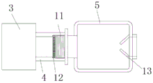
FIG. 2 is a schematic structural view of a connection part of a dust collecting fan and a dust collecting barrel in the cleaning device for chemical production according to the present invention;
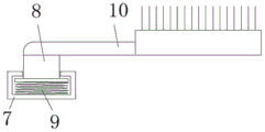
FIG. 3 is a schematic structural diagram of a brush plate installation in a cleaning device for chemical production according to the present invention;
fig. 4 is a schematic structural diagram of the installation of the guide wheel in the cleaning device for chemical production according to the present invention.
In the figure: the dust collecting device comprises a holding rod 1, a motor 2, a dust collecting fan 3, a mounting pipe 4, a dust collecting barrel 5, a dust collecting opening 6, a first mounting seat 7, a first mounting rod 8, a first spring 9, a brush plate 10, a connecting pipe 11, a filter plate 12, a baffle plate 13, a second mounting seat 14, a second mounting rod 15, a guide wheel 16 and a second spring 17.
Detailed Description
The technical solutions in the embodiments of the present invention will be clearly and completely described below with reference to the drawings in the embodiments of the present invention, and it is obvious that the described embodiments are only a part of the embodiments of the present invention, and not all of the embodiments.
In the description of the present invention, it is to be understood that the terms "center", "longitudinal", "lateral", "length", "width", "thickness", "upper", "lower", "front", "rear", "left", "right", "vertical", "horizontal", "top", "bottom", "inner", "outer", "clockwise", "counterclockwise", and the like, indicate orientations and positional relationships based on those shown in the drawings, and are used only for convenience of description and simplicity of description, and do not indicate or imply that the equipment or element being referred to must have a particular orientation, be constructed and operated in a particular orientation, and thus, should not be considered as limiting the present invention.
Furthermore, the terms "first", "second" and "first" are used for descriptive purposes only and are not to be construed as indicating or implying relative importance or implicitly indicating the number of technical features indicated. Thus, a feature defined as "first" or "second" may explicitly or implicitly include one or more of that feature. In the description of the present invention, "a plurality" means two or more unless specifically defined otherwise.
Referring to fig. 1-4, a cleaning device for chemical production comprises a holding rod 1, wherein a motor 2 is fixed at one end of the holding rod 1, the holding rod 1 is a telescopic rod and is convenient to carry, a handle is arranged at one end of the holding rod 1, which is far away from the motor 2, a dust suction fan 3 is installed on an output shaft of the motor 2, an installation pipe 4 is arranged at the input end of the dust suction fan 3, a filter plate 12 is clamped in the installation pipe 4, a stepped surface is arranged inside a connecting pipe 11, the filter plate 12 is clamped on the stepped surface, a sealing strip is arranged on the outer wall of the filter plate 12, and a dust collection barrel 5 is detachably installed on the installation pipe 4;
the first embodiment is as follows:
one end of the dust collection cylinder 5 close to the dust collection fan 3 is welded with a connecting pipe 11, the connecting pipe 11 is in threaded connection with the installation pipe 4, and the connecting pipe 11 and the installation pipe 4 are provided with threads matched with each other.
Example two:
one end of the dust collection cylinder 5 close to the dust collection fan 3 is welded with a connecting pipe 11, and the connecting pipe 11 is connected with the installation pipe 4 in a clamping manner.
Example three:
one end of the dust collection cylinder 5, which is close to the dust collection fan 3, is welded with a connecting pipe 11, the connecting pipe 11 is sleeved on the mounting pipe 4, and the connecting pipe 11 is fixedly connected with the mounting pipe 4 through a screw.
One end of the dust collection barrel 5, which is far away from the dust collection fan 3, is provided with a dust collection port 6, the inner side of the dust collection port 6 is provided with a baffle 13, the baffle 13 is obliquely arranged towards the middle of the dust collection port 6, the phenomenon that sucked dust flows out of the dust collection barrel again is reduced, the two sides of the dust collection barrel 5 are both fixed with first installation seats 7, one end, which is far away from the dust collection barrel 5, of each first installation seat 7 is inserted with a first installation rod 8, the first installation rod 8 is in sliding fit with the first installation seats 7, one end, which is located inside the first installation seats 7, of each first installation rod 8 is provided with a first spring 9, and the outer end of each first installation rod 8 is transversely fixed with a brush plate 10.
Further, both sides of the motor 2 are all fixed with second installation bases 14, one end of each second installation base 14, which is far away from each other, is inserted with a second installation rod 15, one end of each second installation rod 15, which is located inside the second installation base 14, is provided with a second spring 17, a slot is formed in the second installation base 14, the second installation rod 15 is inserted with the slot, the second installation rod 15 is in sliding fit with the inner wall of the slot, the second spring 17 is located in the slot, a guide wheel 16 is installed at the outer end of the second installation rod 15, and the device is supported in the pipeline by the guide wheel 16.
In this embodiment, when using, stretch into the pipeline that needs the clearance brush board 10, extrude first installation pole 8 through first spring 9, make brush board 10 and the laminating of pipeline inner wall, open motor 2 and dust absorption fan 3, motor 2 drives dust absorption fan 3, dust collection tube 5 rotates with brush board 10, clear up the pipeline inner wall through brush board 10, the dust of clearing up out is adsorbed to dust collection tube 5 through dust absorption mouth 6 by dust absorption fan 3 simultaneously, collect the dust, reduce the raise dust phenomenon of job site, the work efficiency of pipeline clearance has been improved, after the clearance is accomplished, through dismantling dust collection tube 5, be convenient for pour out inside dust.
The above description is only for the preferred embodiment of the present invention, but the scope of the present invention is not limited thereto, and any person skilled in the art should be considered to be within the technical scope of the present invention, and the technical solutions and the inventive concepts thereof according to the present invention should be equivalent or changed within the scope of the present invention.
Claims (7)
1. A cleaning device for chemical production comprises a holding rod (1), and is characterized in that a motor (2) is fixed at one end of the holding rod (1), a dust suction fan (3) is mounted on an output shaft of the motor (2), an installation pipe (4) is arranged at the input end of the dust suction fan (3), a filter plate (12) is connected in the installation pipe (4) in a clamping manner, and a dust collection cylinder (5) is detachably mounted on the installation pipe (4);
the dust collection device is characterized in that a dust collection port (6) is formed in one end, away from the dust collection fan (3), of the dust collection barrel (5), first installation seats (7) are fixed on two sides of the dust collection barrel (5), first installation rods (8) are inserted into one ends, away from the dust collection barrel (5), of the first installation seats (7), the first installation rods (8) are in sliding fit with the first installation seats (7), first springs (9) are arranged at one ends, located inside the first installation seats (7), of the first installation rods (8), and brush plates (10) are transversely fixed at the outer ends of the first installation rods (8).
2. The cleaning device for chemical production according to claim 1, wherein the holding rod (1) is a telescopic rod, and a handle is arranged at one end of the holding rod (1) far away from the motor (2).
3. The cleaning device for chemical production according to claim 1, wherein second installation seats (14) are fixed on both sides of the motor (2), a second installation rod (15) is inserted into one end of each second installation seat (14) far away from each other, a second spring (17) is arranged at one end of each second installation rod (15) located inside the second installation seat (14), and a guide wheel (16) is installed at the outer end of each second installation rod (15).
4. A cleaning device for chemical production according to claim 3, characterized in that a slot is opened in the second mounting seat (14), the second mounting rod (15) is inserted into the slot, the second mounting rod (15) is in sliding fit with the inner wall of the slot, and the second spring (17) is located in the slot.
5. A cleaning device for chemical production according to claim 1, characterized in that one end of the dust collecting cylinder (5) close to the dust suction fan (3) is provided with a connecting pipe (11), and the connecting pipe (11) is in threaded connection with the mounting pipe (4).
6. The cleaning device for chemical production according to claim 1, wherein the connecting pipe (11) is provided with a stepped surface inside, the filter plate (12) is clamped on the stepped surface, and the outer wall of the filter plate (12) is provided with a sealing strip.
7. A cleaning device for chemical production according to claim 1, characterized in that a baffle (13) is arranged at the inner side of the dust suction opening (6), and the baffle (13) is inclined towards the middle of the dust suction opening (6).
Priority Applications (1)
| Application Number | Priority Date | Filing Date | Title |
|---|---|---|---|
| CN202110544039.XA CN113198810A (en) | 2021-05-19 | 2021-05-19 | A cleaning device for chemical production |
Applications Claiming Priority (1)
| Application Number | Priority Date | Filing Date | Title |
|---|---|---|---|
| CN202110544039.XA CN113198810A (en) | 2021-05-19 | 2021-05-19 | A cleaning device for chemical production |
Publications (1)
| Publication Number | Publication Date |
|---|---|
| CN113198810A true CN113198810A (en) | 2021-08-03 |
Family
ID=77031722
Family Applications (1)
| Application Number | Title | Priority Date | Filing Date |
|---|---|---|---|
| CN202110544039.XA Withdrawn CN113198810A (en) | 2021-05-19 | 2021-05-19 | A cleaning device for chemical production |
Country Status (1)
| Country | Link |
|---|---|
| CN (1) | CN113198810A (en) |
Cited By (1)
| Publication number | Priority date | Publication date | Assignee | Title |
|---|---|---|---|---|
| CN114378071A (en) * | 2022-01-19 | 2022-04-22 | 杨清哲 | Wisdom water utilities pipeline inner wall deposit cleaning device |
-
2021
- 2021-05-19 CN CN202110544039.XA patent/CN113198810A/en not_active Withdrawn
Cited By (1)
| Publication number | Priority date | Publication date | Assignee | Title |
|---|---|---|---|---|
| CN114378071A (en) * | 2022-01-19 | 2022-04-22 | 杨清哲 | Wisdom water utilities pipeline inner wall deposit cleaning device |
Similar Documents
| Publication | Publication Date | Title |
|---|---|---|
| CN210934244U (en) | Desktop hole drilling machine dust collection device | |
| CN217082819U (en) | Building is warm to lead to and is used high-efficient ventilation unit | |
| CN112089358B (en) | A dead angle cleaning mechanism based on computer case cleaning | |
| CN110883455B (en) | Photoelectronic device coupling welding equipment | |
| CN210229431U (en) | Wall-mounted air cleaner for workshop | |
| CN215575069U (en) | Self-cleaning device for in-situ water quality monitoring | |
| CN215311037U (en) | Filter cartridge dust remover convenient for filter cartridge replacement | |
| CN216495132U (en) | Liftable cleaning device for indoor wall surface ceiling | |
| CN217529281U (en) | Three-side drilling machine for valve turbine head | |
| CN216323731U (en) | Automatic wash pH value detecting instrument equipment | |
| CN212410111U (en) | Sampling device is used in construction with clean function | |
| CN210124712U (en) | Convenient textile mill that removes uses dust catcher | |
| CN222196280U (en) | Pulse dust collector | |
| CN220361575U (en) | A maintenance device for copper brush holder processing | |
| CN223748198U (en) | Discharging hopper cleaning and dust removing device | |
| CN221734368U (en) | A dust removal device for environmental engineering | |
| CN217772197U (en) | Dry-wet dual-purpose dust collector capable of preventing sewage backflow | |
| CN214945074U (en) | Industrial dustproof centrifugal fan | |
| CN218154723U (en) | New forms of energy air purification equipment | |
| CN214555604U (en) | A MOS tube switch dust removal device | |
| CN219118040U (en) | Adjustable garbage pickup for road cleaning | |
| CN218901242U (en) | Waste gas collection monitoring facilities | |
| CN220434302U (en) | Concrete construction joint face cleaning device | |
| CN221696245U (en) | Sharpening machine for transverse bar milling cutter of roller | |
| CN221966842U (en) | A drilling device for processing stainless steel water tanks |
Legal Events
| Date | Code | Title | Description |
|---|---|---|---|
| PB01 | Publication | ||
| PB01 | Publication | ||
| WW01 | Invention patent application withdrawn after publication |
Application publication date: 20210803 |
|
| WW01 | Invention patent application withdrawn after publication |