Detailed Description
The technical solutions in the embodiments of the present application will be clearly and completely described below with reference to the drawings in the embodiments of the present application, and it is obvious that the described embodiments are some, but not all, embodiments of the present application. All other embodiments, which can be derived by a person skilled in the art from the embodiments given herein without making any creative effort, shall fall within the protection scope of the present application.
The terms first, second and the like in the description and in the claims of the present application are used for distinguishing between similar elements and not necessarily for describing a particular sequential or chronological order. It will be appreciated that the data so used may be interchanged under appropriate circumstances such that embodiments of the application may be practiced in sequences other than those illustrated or described herein, and that the terms "first," "second," and the like are generally used herein in a generic sense and do not limit the number of terms, e.g., the first term can be one or more than one. In addition, "and/or" in the specification and claims means at least one of connected objects, a character "/" generally means that a preceding and succeeding related objects are in an "or" relationship.
The electronic device provided by the embodiment of the present application is described in detail with reference to fig. 1 to 16 through specific embodiments and application scenarios thereof.
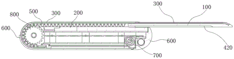
The electronic device disclosed by one embodiment of the invention comprises a first support 100, a second support 200, a flexible screen 300 and a shell 600, wherein the shell 600 is a structural member and provides an installation foundation for the first support 100, the second support 200 and/or the flexible screen 300.
The first and second supports 100 and 200 may be provided to the case 600. Wherein, an accommodating space may be formed between the first side of the second support 200 and the housing 600, so that at least a portion of the flexible screen 300 may be received in the accommodating space. Specifically, the display area is reduced by partially housing the flexible screen 300 in the housing space, and the display area is widened by sliding out the flexible screen 300 housed in the housing space.
The first support 100 may be stacked on the second side of the second support 200, and the first support 100 may be slidably engaged with the second support 200 and/or the case 600 such that at least a portion of the first support 100 may slide out of the edge of the case 600. The first side of the second support 200 may be opposite to the second side of the second support 200. A first section of flexible screen 300 is attached to first support 100 and a second section of flexible screen 300 is slip-fitted to second support 200. In a case where the second support 200 slides in a direction away from the first support 100, the second section of the flexible screen 300 protrudes out of the accommodation space, i.e., the second section of the flexible screen 300 moves in a direction protruding out of the accommodation space. The second section of the flexible screen 300 moves from the first side of the second support member 200 to the second side of the second support member 200, so that the second section of the flexible screen 300 can be located at the same side of the second support member 200 as the first section of the flexible screen 300 after extending out of the accommodating space, thereby increasing the display area. In the case where the second support 200 slides in a direction to approach the first support 100, the second section of the flexible screen 300 is retracted into the accommodation space, i.e., the second section of the flexible screen 300 moves in a direction to be retracted into the accommodation space. The second section of the flexible screen 300 moves from the second side of the second support member 200 to the first side of the second support member 200, so that the second section of the flexible screen 300 can be located at the opposite side of the second support member 200 from the first section of the flexible screen 300 after retracting into the accommodating space, thereby reducing the display area.
In the above embodiment, the first support 100 slides out from the edge of the casing 600 along the second support 200, and drives the second section of the flexible screen 300 to slide out from the accommodating space, so as to increase the display area of the electronic device. In the process of increasing the display area, the width, the length and the thickness of the casing 600 do not change, that is, the casing 600 does not participate in the movement of adjusting the display area, so that the user can adjust the display area of the electronic device without adjusting the posture of holding the electronic device, the user can hold the electronic device conveniently, and the portability of the electronic device is improved. Specifically, for an electronic device that can be held with a single hand, a user can adjust the size of the display area of the electronic device with a single hand by holding the housing 600.
One of the purposes of the second support member 200 is to support the second section of the flexible screen 300, so that the flexible screen 300 can be bent along the second support member 200, and then the second section of the flexible screen 300 can be accommodated in the accommodating space, thereby reducing the display area, or the second section of the flexible screen 300 can be extended out of the accommodating space along the second support member 200, and then the second section of the flexible screen 300 and the first section of the flexible screen 300 can be located on the same side of the housing 600, thereby increasing the display area. The second supporting member 200 may be a rail disposed on the casing 600, or may be a supporting plate or a supporting frame disposed on the casing 600.
Referring to fig. 8 and 9, one of the purposes of the first support 100 is to support the first section of the flexible screen 300 to ensure flatness of the first section of the flexible screen 300. The first support 100 may include a support plate through which a first section of the flexible screen 300 is supported to prevent the first section of the flexible screen 300 from being depressed by a force. Alternatively, the first support 100 may be provided as a support plate to reduce the thickness of the first support 100, and then the thickness of the side of the casing 600 close to the side where the first support 100 slides out may be increased to protrude the side of the first support 100 close to the second support 200, so as to provide a larger holding surface for a user to hold.
In an alternative embodiment, the user can manually toggle the first support 100 and move the second section of the flexible screen 300 relative to the second support 200, thereby increasing or decreasing the display area of the electronic device.
In another alternative embodiment, the electronic device may further include a driving mechanism 400, so that the driving mechanism 400 drives the first support 100 and drives the second segment of the flexible screen 300 to move relative to the second support 200, thereby increasing or decreasing the display area of the electronic device.
The driving mechanism 400 may include a link mechanism 420 and a driving member 410, the driving member 410 is disposed on the first support 100, a first end of the link mechanism 420 is connected to the driving member 410, a second end of the link mechanism 420 is connected to the second support 200, and the driving member 410 drives the link mechanism 420 and drives the second support 200 to move relative to the first support 100 through the link mechanism 420. The linkage mechanism 420 is of many types, for example: a crank-link mechanism, a rocker mechanism, a crank-rocker mechanism, etc., for which the present embodiment does not limit the specific type of link mechanism 420.
Referring to fig. 1 to 12, the link mechanism 420 may include a first link 421, a second link 422, and a connecting shaft 423, a first end of the first link 421 is rotatably coupled to a first end of the second link 422 through the connecting shaft 423, a second end of the first link 421 is rotatably coupled to the driving member 410, a second end of the second link 422 is rotatably coupled to the second support member 200, and the driving member 410 drives the first link 421 to rotate around the second end of the first link 421 and drives the second support member 200 to move relative to the first support member 100 through the first link 421 and the second link 422. Specifically, the driving member 410 drives the first link 421 to rotate, and the first end of the first link 421 pushes the second link 422, so that the second link 422 can drive the first supporting member 100 to move relative to the second supporting member 200.
Referring to fig. 2, 3, 6 and 8, the connection point of the second link 422 and the first support 100 may be located at a side of the first support 100 away from the second section of the flexible screen 300, so that when the first support 100 slides out of the edge of the casing 600, the second link 422 may at least partially extend out of the casing 600 to provide support for the first support 100 to improve the stability of the first support 100.
Referring to fig. 12 and 13, the link mechanism 420 may further include an elastic member 424, one end of the elastic member 424 is connected to the first link 421, the second end of the elastic member 424 is connected to the second link 422, and the elastic member 424 may drive the first link 421 to rotate relative to the second link 422, thereby assisting the first link 421 and the second link 422 to unfold and push the first support 100 away from the second support 200. The elastic member 424 can reduce the resistance of the driving member 410 to driving the link mechanism 420, so that the first supporting member 100 can move smoothly relative to the second supporting member 200. The elastic member 424 may be a torsion spring. Specifically, the connecting shaft 423 may be sleeved with the torsion spring, the first end of the torsion spring is connected to the first connecting rod 421, and the second end of the torsion spring is connected to the second connecting rod 422, so as to assist the first connecting rod 421 and the second connecting rod 422 to return through the torsion spring.
Referring to fig. 5 to 8, the second supporting member 200 may include a first carrier plate 210, the first carrier plate 210 is supported on the second section of the flexible screen 300 and/or the first supporting member 100, the driving member 410 and the first connecting rod 421 are disposed on a side of the first carrier plate 210 departing from the first supporting member 100, and the second connecting rod 422 is disposed between the first carrier plate 210 and the first supporting member 100. The first carrier plate 210 is provided with a slide 211. The slide 211 may be a through hole in conformity with the moving trace of the connecting shaft 423. The connecting shaft 423 penetrates through the slide 211, a first end of the connecting shaft 423 is connected with the first connecting rod 421, a second end of the connecting shaft 423 is connected with the second connecting rod 422, and the connecting shaft 423 moves in the slide 211 under the action of the first connecting rod 421. The driving member 410 and the first link 421 are disposed on a side of the first loading plate 210 away from the first supporting member 100, so that a gap between the first loading plate 210 and the first supporting member 100 can be reduced, and the assembly of the first supporting member 100 and the second supporting member 200 is more compact. Further, the second connecting rod 422 is disposed between the first bearing plate 210 and the first supporting member 100, so that the second connecting rod 422 and the first connecting rod 421 are respectively located at two sides of the first bearing plate 210, the first connecting rod 421 and the second connecting rod 422 are connected by the connecting shaft 423, and further the first connecting rod 421 and the second connecting rod 422 can be attached to the surface of the first bearing plate 210 under the action of the connecting shaft 423, so that the assembly of the connecting rod mechanism 420 and the first bearing plate 210 is more compact. Referring to fig. 3 and 4, in the case that the first support 100 slides out of the casing 600, the second link 422 has a movement tendency of rotating around the edge supporting point of the second link 422 and the casing 600 under the action of the first support 100, in the above embodiment, the second link 422 and the first link 421 are connected by the connecting shaft 423, so that the second link 422 can be supported on the side of the first loading plate 210 departing from the first support 100 through the first link 421, and further, the two ends of the second link 422 are balanced in stress, thereby improving the stability of the second link 422.
Referring to fig. 5 to 8, the first supporting plate 210 may include a first avoiding groove 212 and a second avoiding groove 213, the first link 421 is at least partially located in the first avoiding groove 212, and the first link 421 moves in the first avoiding groove 212. The second link 422 is at least partially located in the second avoiding groove 213, and the first link 421 can drive the second link 422 to move in the second avoiding groove 213. The first avoiding groove 212 may be disposed in a fan shape, and the first link 421 may be defined by the wall of the first avoiding groove 212 being stopped by the first link 421, so as to prevent the first support 100 from moving excessively relative to the second support 200. In this embodiment, the first avoiding groove 212 and the second avoiding groove 213 not only can improve the compactness between the first bearing plate 210 and the link mechanism 420 and reduce the space occupied by the link mechanism 420, but also can limit the moving direction moving range of the first link 421 and the second link 422 by using the first avoiding groove 212 and the second avoiding groove 213.
Referring to fig. 14 and 15, the driving member 410 may include a driving motor 411 and a gear box 412, the gear box 412 including a power input shaft 4121 and a power output shaft 4123, the power input shaft 4121 being connected to the driving motor 411, and the power output shaft 4123 being connected to the first link 421. The gear box 412 may not only be used to increase the maximum torque output by the driving member 410, but also may perform a speed reduction function to facilitate precise adjustment of the size of the display area.
Referring to fig. 14 and 15, the gear box 412 may include a transmission shaft 4122, a first end of the transmission shaft 4122 being provided with a first gear, a second end of the transmission shaft 4122 being provided with a second gear, the power input shaft 4121 being provided with a third gear, the power output shaft 4123 being provided with a fourth gear, the third gear being engaged with the first gear, the second gear being engaged with the fourth gear. The radius of the third gear is smaller than that of the first gear, and the radius of the second gear is smaller than that of the fourth gear, so that the maximum torque which can be output by the power output shaft 4123 is larger than that of the power input shaft 4121. Further, the driving motor 411 and the power output shaft 4123 are in gear transmission, and the transmission ratio of the driving motor 411 to the power input shaft 4121 is greater than 1. The power output shaft 4123 and the first link 421 can be geared, and the gear ratio of the power output shaft 4123 and the first link 421 is greater than 1, so that the maximum torque that can be output by the first link 421 is greater than the maximum torque that can be output by the power output shaft 4123.
Referring to fig. 5 to 12, the number of the power output shafts 4123 and the link mechanisms 420 may be two, the two link mechanisms 420 are symmetrically distributed on two sides of the first support member 100 and/or the second support member 200, the two power output shafts 4123 are symmetrically distributed on two sides of the transmission shaft 4122, and the link mechanisms 420 and the power output shafts 4123 are correspondingly connected one to one, so that the stress on the first support member 100 is balanced, and the first support member 100 is prevented from being jammed during the movement process relative to the second support member 200.
Third support 500 may be disposed on a side of the second section of flexible screen 300 near second support 200, and third support 500 may move along second support 200 with the second section of flexible screen 300. In case the third support 500 is moved to the second side of the second support 200, i.e. the second section of the flexible screen 300 is located on the same side of said second support 200 as the first section of said flexible screen 300, the side of the third support 500 facing away from the flexible screen 300 may be supported on the second support 200. The third supporting member 500 moves along the second supporting member 200 along with the flexible screen 300, so that the height difference between the second supporting member 200 and the first supporting member 100 can be compensated by the third supporting member 500, so that the third supporting member 500 can be supported on the second supporting member 200 when the first section of the flexible screen 300 moves to the second side of the second supporting member 200, thereby preventing the second section of the flexible screen 300 from sinking after being stressed. Optionally, the thickness of the second support 200 is not less than the thickness of the screen support plate supporting the first segment of the flexible screen 300 on the first support 100.
In the above embodiment, the third supporting member 500 moves along the second supporting member 200 along with the flexible screen 300, and can dynamically support the second section of the flexible screen 300, that is, the area of the second side of the second supporting member 200 of the third supporting member 500 is always equal to the area of the second side of the second supporting member 200 of the second section of the flexible screen 300, so as to ensure that the third supporting member 500 can provide effective support for the second section of the flexible screen 300, and prevent the second section of the flexible screen 300 from sinking after being stressed. Because the third supporting member 500 and the flexible screen 300 move synchronously, the display area of the display screen of the electronic device can be adjusted steplessly within the adjustable range of the display area, and the flexible screen 300 can be supported effectively within the adjustable range of the display area of the display screen, so that the flexible screen 300 is prevented from being depressed. In addition, the third supporting member 500 is located at a side of the second section of the flexible screen 300 close to the second supporting member 200, so that mutual friction between the flexible screen 300 and the second supporting member 200 can be avoided, abrasion of the flexible screen 300 is avoided, and the service life of the flexible screen 300 is prolonged.
One end of the third supporting member 500 close to the first supporting member 100 may be connected to the first supporting member 100, so that the first supporting member 100 may directly pull the third supporting member 500 to move along the surface of the second supporting member 200, thereby reducing the stress on the flexible screen 300 and achieving the purpose of protecting the flexible screen 300.
Referring to fig. 10, the width and/or length of third support 500 may be not less than the width and/or length of the second section of flexible screen 300 to enable third support 500 to effectively support the second section of flexible screen 300. Referring to fig. 5 and 6, optionally, the second side of the second support 200 is provided with a support surface on which the third support 500 may be supported to provide a stable supporting force for the flexible screen 300. Moreover, the second side of the second supporting member 200 is provided with a supporting surface, which can reduce the requirement on the hardness of the third supporting member 500, and further provide a wider material selection space for the third supporting member 500, and the hardness of the third supporting member 500 can be reduced under the support of the supporting surface of the second side of the second supporting member 200. Optionally, the third supporting member 500 may be a supporting layer made of a flexible material, so that the third supporting member 500 can be bent after being stressed, and further the third supporting member 500 can be moved along the surface of the third supporting member 500 under the driving of the first supporting member 100. Further, a side of the third support 500 facing away from the flexible screen 300 is provided with a "V" shaped groove to reduce internal stress generated after the third support 500 is bent.
There are many types of flexible materials, such as: polyester elastomer materials, propylene-based elastomer materials, vinyl elastomer materials, fluoro/silicone elastomer materials, and the like. Therefore, the specific material of the third supporting member 500 is not limited in the present application.
Referring to fig. 4, 10 to 12, the third support 500 may further include a plurality of support bodies 520, the support bodies 520 are elongated, the support bodies 520 are disposed in parallel and spaced apart on a side of the flexible screen 300 close to the second support 200, and the support bodies 520 are perpendicular to the moving direction of the flexible screen 300. The plurality of support bodies 520 are disposed in parallel and spaced apart on the flexible screen 300, that is, adjacent two support bodies 520 may be connected by the flexible screen 300, so that the third support 500 may be bent at a gap between the adjacent two support bodies 520, and thus the third support 500 may be bent along the surface of the second support 200. The length direction of the support body 520 is perpendicular to the moving direction of the flexible screen 300, so that the support body 520 may be bent along the edge of the second support 200, enabling the third support 500 to be better supported on the second support 200. The width of the side of the support body 520 close to the flexible screen 300 may be greater than the width of the side of the support body 520 far from the flexible screen 300, so that a "V" or wedge-shaped gap is formed between two adjacent support bodies 520, and thus the area of the support body 520 supporting the flexible screen 300 may be increased while avoiding mutual pressing of the two support bodies 520. The supporting body 520 can be made of hard materials to reduce the deformation of the supporting body 520 after being stressed, so that better support is provided for the flexible screen 300, and the flexible screen 300 is prevented from being depressed after being stressed.
It should be noted that one of the purposes of the support body 520 is to support the flexible screen 300 so as to prevent the flexible screen 300 from being depressed when a user operates on the flexible screen 300. That is, the support main body 520 may support the flexible screen 300 so that the user cannot perceive the deformation of the flexible screen 300 when operating on the flexible screen 300. Therefore, materials that enable the amount of deformation of the support body 520 to be imperceptible to the user under the force of the user acting on the flexible screen 300 may be suitable for the support body 520 described in the above embodiments. There are many materials suitable for making the support body 520, for example: polyvinyl chloride, polypropylene, polystyrene, and the like. Therefore, the specific material of the support body 520 is not limited in the present application.
The third support 500 may further include a flexible connector 510, and the flexible connector 510 is disposed on a side of the support body 520 close to the flexible screen 300, that is, the plurality of support bodies 520 may be connected by the flexible connector 510, so as to reduce the stress on the flexible screen 300. The flexible connector 510 is connected to the flexible screen 300 and/or the first support 100 so that the support body 520 can move along the surface of the second support 200 with the flexible screen 300. The flexible connecting member 510 is connected to the first supporting member 100, and when the first supporting member 100 is far away from the second supporting member 200, the first supporting member 100 can directly drive the flexible connecting member 510, so as to drive the supporting bodies 520 to move, thereby reducing the stress on the flexible screen 300 and achieving the purpose of protecting the flexible screen 300. Of course, flexible connector 510 may also be connected to a second section of flexible screen 300, and the second section of flexible screen 300 may be used to move flexible connector 510 relative to second support member 200. Specifically, flexible connector 510 may be fixedly attached to a side of the second section of flexible screen 300 adjacent to second support member 200. Of course, the flexible connector 510 may also be connected to both the first support member 100 and the second section of the flexible screen 300.
The flexible connector 510 may be made of a flexible material. There are many types of flexible materials, such as: polyester elastomer materials, propylene-based elastomer materials, vinyl elastomer materials, fluoro/silicone elastomer materials, and the like. The specific material of the flexible connecting member 510 is not limited in this application.
Referring to fig. 3 to 6, the electronic apparatus may further include a transmission gear 800, and the transmission gear 800 may be rotatably provided to the second support 200. The teeth of the transmission gear 800 are engaged with the supporting body 520, and when the first supporting member 100 slides relative to the second supporting member 200, the third supporting member 500 drives the transmission gear 800 to rotate, and the second section of the flexible screen 300 can be switched between the first side of the second supporting member 200 and the second side of the second supporting member 200 along the engaging surface of the transmission gear 800 and the third supporting member 500.
In the above embodiment, the transmission gear 800 may convert the sliding fit between the bending of the flexible screen 300 and the second support 200 into a rotation pair between the transmission gear 800 and the second support 200, so as to effectively reduce the resistance of the second support 200 moving along the surface of the second support 200, reduce the tensile force applied to the third support 500 and/or the flexible screen 300, and reduce the wear amount of the contact surface between the third support 500 and the second support 200. In addition, the teeth of the transfer gear 800 are engaged with the gaps between the adjacent two support bodies 520, so that the transfer gear 800 can play a role in guiding and positioning during the bending of the third support 500 to avoid the excessive pressing between the adjacent two support bodies 520.
Referring to fig. 4 and 12, as the support bodies 520 are engaged with the transfer gear 800, the support bodies 520 slide into the gaps between the teeth in the transfer gear 800 along the edges of the teeth of the transfer gear 800, and as the support bodies 520 are fitted into the gaps between the teeth in the transfer gear 800, the interval between the sides of the adjacent two support bodies 520 away from the flexible link 510 is reduced while the degree of bending of the third support 500 is gradually increased, i.e., the transfer gear 800 has an effect of guiding the third support 500 to be bent and deformed. Because the teeth of the transmission gear 800 are embedded into the gap between two adjacent supporting bodies 520, the teeth of the transmission gear 800 can support the two adjacent supporting bodies 520, and the gap between the two adjacent supporting bodies 520 is prevented from being too small, so that the third supporting member 500 and the flexible screen 300 are prevented from being bent excessively, and the purpose of protecting the third supporting member 500 and the flexible screen 300 is achieved.
Referring to fig. 4 and 12, the third support 500 may further include a first support part 530 and a second support part 540, the first support part 530 and the second support part 540 being located at the root of the support body 520. In the case where the flexible screen 300 is bent with a curvature smaller than that of the corresponding circular arc segment of the transfer gear 800, a wedge gap or a "V" gap may be formed between the first and second supporting parts 530 and 540 between the adjacent two supporting bodies 520. In the case where the flexible screen 300 is bent with a curvature greater than or equal to that of the corresponding circular arc segment of the transfer gear 800, the first and second supporting parts 530 and 540 between the adjacent two supporting bodies 520 support each other. In the process that the third supporting member 500 moves along the second supporting member 200, the third supporting member 500 drives the transmission gear 800 to rotate, and then the first supporting portion 530 and the second supporting portion 540 can be utilized to support each other, so as to improve the stability of the supporting main body 520 close to one side of the flexible screen 300 and reduce the pulling force applied to the flexible connecting member 510 and/or the flexible screen 300. The wedge-shaped gap or the "V" shaped gap between the first supporting portion 530 and the second supporting portion 540 may prevent an excessive supporting force between the first supporting portion 530 and the second supporting portion 540, and facilitate the third support 500 and/or the flexible screen 300 to be bent.
The first and second supporting parts 530 and 540 may be made of an elastic material, so that a size error in the manufacturing of the first and second supporting parts 530 and 540 is eliminated by the deformation of the first and second supporting parts 530 and 540, and the stability of the supporting body 520 near the flexible screen 300 may be improved by the elastic force between the first and second supporting parts 530 and 540.
There are many types of elastic materials, for example: polyester elastomer materials, propylene-based elastomer materials, vinyl elastomer materials, fluoro/silicone elastomer materials, and the like. Therefore, the present application does not limit the specific materials of the first supporting portion 530 and the second supporting portion 540.
Referring to fig. 2, the electronic device may further include a screen tensioning member 700, one end of the screen tensioning member 700 being connected to the first support member 100, a second end of the screen tensioning member 700 being connected to the flexible connector 510 and/or the flexible screen 300, the screen tensioning member 700 driving a second section of the flexible screen 300 to move from the second side of the second support member 200 to the first side of the second support member 200. The screen tensioner 700 can provide tension to the flexible screen 300, thereby keeping the flexible screen 300 in a tensioned state. Specifically, the screen tensioning member 700 may be an elastic body, and an end of the flexible screen 300 away from the first support member 100 is pulled by an elastic force generated by the elastic body recovering deformation to move to the first side of the second support member 200, so that the flexible screen 300 is in a tensioned state. Specifically, there are many types of screen tensioning members 700, such as: springs, elastic cords, coil springs or telescoping mechanisms, etc. Embodiments of the present invention do not limit the specific type of screen tensioner 700.
The electronic device disclosed by the embodiment of the application can be a mobile phone, a tablet computer, an electronic book reader, a wearable device and the like, and the embodiment of the application does not limit the specific type of the electronic device.
It should be noted that, in this document, the terms "comprises," "comprising," or any other variation thereof, are intended to cover a non-exclusive inclusion, such that a process, method, article, or apparatus that comprises a list of elements does not include only those elements but may include other elements not expressly listed or inherent to such process, method, article, or apparatus. Without further limitation, an element defined by the phrase "comprising an … …" does not exclude the presence of other like elements in a process, method, article, or apparatus that comprises the element. Further, it should be noted that the scope of the methods and apparatus of the embodiments of the present application is not limited to performing the functions in the order illustrated or discussed, but may include performing the functions in a substantially simultaneous manner or in a reverse order based on the functions involved, e.g., the methods described may be performed in an order different than that described, and various steps may be added, omitted, or combined. In addition, features described with reference to certain examples may be combined in other examples.
While the present embodiments have been described with reference to the accompanying drawings, it is to be understood that the invention is not limited to the precise embodiments described above, which are meant to be illustrative and not restrictive, and that various changes may be made therein by those skilled in the art without departing from the spirit and scope of the invention as defined by the appended claims.