CN113182763B - Tower crane pipeline welding machine tool with multistage adjusting clamping mechanism and operation method thereof - Google Patents
Tower crane pipeline welding machine tool with multistage adjusting clamping mechanism and operation method thereof Download PDFInfo
- Publication number
- CN113182763B CN113182763B CN202110338995.2A CN202110338995A CN113182763B CN 113182763 B CN113182763 B CN 113182763B CN 202110338995 A CN202110338995 A CN 202110338995A CN 113182763 B CN113182763 B CN 113182763B
- Authority
- CN
- China
- Prior art keywords
- clamping
- shaped
- plate
- cylinder
- fixed
- Prior art date
- Legal status (The legal status is an assumption and is not a legal conclusion. Google has not performed a legal analysis and makes no representation as to the accuracy of the status listed.)
- Active
Links
Images




Classifications
-
- B—PERFORMING OPERATIONS; TRANSPORTING
- B23—MACHINE TOOLS; METAL-WORKING NOT OTHERWISE PROVIDED FOR
- B23K—SOLDERING OR UNSOLDERING; WELDING; CLADDING OR PLATING BY SOLDERING OR WELDING; CUTTING BY APPLYING HEAT LOCALLY, e.g. FLAME CUTTING; WORKING BY LASER BEAM
- B23K37/00—Auxiliary devices or processes, not specially adapted for a procedure covered by only one of the other main groups of this subclass
- B23K37/04—Auxiliary devices or processes, not specially adapted for a procedure covered by only one of the other main groups of this subclass for holding or positioning work
- B23K37/053—Auxiliary devices or processes, not specially adapted for a procedure covered by only one of the other main groups of this subclass for holding or positioning work aligning cylindrical work; Clamping devices therefor
-
- B—PERFORMING OPERATIONS; TRANSPORTING
- B23—MACHINE TOOLS; METAL-WORKING NOT OTHERWISE PROVIDED FOR
- B23K—SOLDERING OR UNSOLDERING; WELDING; CLADDING OR PLATING BY SOLDERING OR WELDING; CUTTING BY APPLYING HEAT LOCALLY, e.g. FLAME CUTTING; WORKING BY LASER BEAM
- B23K37/00—Auxiliary devices or processes, not specially adapted for a procedure covered by only one of the other main groups of this subclass
- B23K37/04—Auxiliary devices or processes, not specially adapted for a procedure covered by only one of the other main groups of this subclass for holding or positioning work
- B23K37/047—Auxiliary devices or processes, not specially adapted for a procedure covered by only one of the other main groups of this subclass for holding or positioning work moving work to adjust its position between soldering, welding or cutting steps
-
- B—PERFORMING OPERATIONS; TRANSPORTING
- B23—MACHINE TOOLS; METAL-WORKING NOT OTHERWISE PROVIDED FOR
- B23K—SOLDERING OR UNSOLDERING; WELDING; CLADDING OR PLATING BY SOLDERING OR WELDING; CUTTING BY APPLYING HEAT LOCALLY, e.g. FLAME CUTTING; WORKING BY LASER BEAM
- B23K37/00—Auxiliary devices or processes, not specially adapted for a procedure covered by only one of the other main groups of this subclass
- B23K37/04—Auxiliary devices or processes, not specially adapted for a procedure covered by only one of the other main groups of this subclass for holding or positioning work
- B23K37/053—Auxiliary devices or processes, not specially adapted for a procedure covered by only one of the other main groups of this subclass for holding or positioning work aligning cylindrical work; Clamping devices therefor
- B23K37/0531—Internal pipe alignment clamps
-
- B—PERFORMING OPERATIONS; TRANSPORTING
- B23—MACHINE TOOLS; METAL-WORKING NOT OTHERWISE PROVIDED FOR
- B23K—SOLDERING OR UNSOLDERING; WELDING; CLADDING OR PLATING BY SOLDERING OR WELDING; CUTTING BY APPLYING HEAT LOCALLY, e.g. FLAME CUTTING; WORKING BY LASER BEAM
- B23K37/00—Auxiliary devices or processes, not specially adapted for a procedure covered by only one of the other main groups of this subclass
- B23K37/04—Auxiliary devices or processes, not specially adapted for a procedure covered by only one of the other main groups of this subclass for holding or positioning work
- B23K37/053—Auxiliary devices or processes, not specially adapted for a procedure covered by only one of the other main groups of this subclass for holding or positioning work aligning cylindrical work; Clamping devices therefor
- B23K37/0533—External pipe alignment clamps
-
- Y—GENERAL TAGGING OF NEW TECHNOLOGICAL DEVELOPMENTS; GENERAL TAGGING OF CROSS-SECTIONAL TECHNOLOGIES SPANNING OVER SEVERAL SECTIONS OF THE IPC; TECHNICAL SUBJECTS COVERED BY FORMER USPC CROSS-REFERENCE ART COLLECTIONS [XRACs] AND DIGESTS
- Y02—TECHNOLOGIES OR APPLICATIONS FOR MITIGATION OR ADAPTATION AGAINST CLIMATE CHANGE
- Y02P—CLIMATE CHANGE MITIGATION TECHNOLOGIES IN THE PRODUCTION OR PROCESSING OF GOODS
- Y02P70/00—Climate change mitigation technologies in the production process for final industrial or consumer products
- Y02P70/10—Greenhouse gas [GHG] capture, material saving, heat recovery or other energy efficient measures, e.g. motor control, characterised by manufacturing processes, e.g. for rolling metal or metal working
Landscapes
- Physics & Mathematics (AREA)
- Optics & Photonics (AREA)
- Engineering & Computer Science (AREA)
- Mechanical Engineering (AREA)
- Butt Welding And Welding Of Specific Article (AREA)
- Arc Welding In General (AREA)
Abstract
Description
技术领域technical field
本发明涉及塔吊焊接技术领域,尤其涉及具有多级调节夹持机构的塔吊管道焊接机具及其操作方法。The invention relates to the technical field of tower crane welding, in particular to a tower crane pipeline welding machine tool with a multi-stage adjustable clamping mechanism and an operating method thereof.
背景技术Background technique
塔吊是建筑工地上常用的工程起重设备,标准节是塔吊的主要组件之一,用于构成塔吊的塔杆部分。通过控制标准节的数量实现对塔吊高度的控制,标准节的结构一般包括四侧的主弦杆以及连接与各主弦杆之间的连接梁与桁架,特殊情况需要采用不同直径的管道进行焊接形成标准节。Tower cranes are commonly used engineering lifting equipment on construction sites, and the standard section is one of the main components of the tower crane, which is used to form the tower part of the tower crane. The height of the tower crane is controlled by controlling the number of standard sections. The structure of the standard section generally includes main chords on four sides and connecting beams and trusses connected to each main chord. In special cases, pipes of different diameters are required for welding. Form a standard section.
但针对塔吊标准节焊接时,需要采用固定装置对管道进行固定,但传统的固定装置存在以下缺点:1、只能对两个长度相同的管道进行焊接固定到一起,对两个不同直径的管道进行焊接的工装尚不具备,且针对管道的夹持固定和普通的长管夹持固定方式有所不同,导致夹持固定的过程中,容易出现夹持偏移错位,导致夹持的稳定性比较差;2、由于两个管道的接触面是圆形的,所以需要手动不停的翻转两个管道,由于两个管道的直径不同,在翻转时很难保证两个管道管可以同轴、同速度一起旋转,稍不注意,很容易使焊接面断裂。However, when welding the standard section of the tower crane, it is necessary to use a fixing device to fix the pipe, but the traditional fixing device has the following disadvantages: 1. Only two pipes with the same length can be welded and fixed together, and two pipes with different diameters The tooling for welding is not yet available, and the clamping and fixing methods for pipes are different from those of ordinary long pipes, which leads to clamping offset and misalignment during the clamping and fixing process, resulting in clamping stability. Relatively poor; 2. Since the contact surface of the two pipes is circular, the two pipes need to be turned over manually. Because the diameters of the two pipes are different, it is difficult to ensure that the two pipes can be coaxial and Rotating at the same speed, if you don't pay attention, it is easy to break the welding surface.
发明内容Contents of the invention
本发明的目的是为了解决现有技术中存在的短钢管夹持固定不牢及同轴焊接不便的缺点,而提出的具有多级调节夹持机构的塔吊管道焊接机具。The object of the present invention is to solve the shortcoming of short steel pipe clamping and fixing in the prior art and the inconvenience of coaxial welding, and proposes a tower crane pipeline welding machine tool with multi-stage adjustment clamping mechanism.
为了解决现有技术存在的短钢管夹持固定不牢及同轴焊接不便的问题,本发明采用了如下技术方案:In order to solve the problems of weak clamping and fixing of short steel pipes and inconvenient coaxial welding existing in the prior art, the present invention adopts the following technical solutions:
具有多级调节夹持机构的塔吊管道焊接机具,包括底板、夹持组件、扩张组件、驱动机构、焊接机构,所述底板为水平横向放置的矩形板状,所述底板的底面四个拐角处均设有支撑底座,所述底板的顶面两侧设有一对竖向对称固接的竖板,每块所述竖板的中部均横向开设有通孔,每个所述通孔内均安装有固定轴承环;A tower crane pipe welding machine with a multi-stage adjustable clamping mechanism, including a bottom plate, a clamping assembly, an expansion assembly, a driving mechanism, and a welding mechanism. The bottom plate is in the shape of a rectangular plate placed horizontally and horizontally. Both are provided with supporting bases, and a pair of vertically symmetrical vertical plates are arranged on both sides of the top surface of the bottom plate, and a through hole is opened horizontally in the middle of each of the vertical plates, and each of the through holes is installed With fixed bearing ring;
每个所述固定轴承环内均横向插设有固定贯穿的固定筒,每个所述固定筒的里端部均安装有夹持组件,每个所述固定筒的外端部均安装有扩张组件,每块所述竖板的底部均安装有驱动机构,两块所述竖板的顶部之间设有横向放置的横板,所述横板的两端分别与两块竖板的顶端固接,所述横板的底面设有焊接机构;Each of the fixed bearing rings is horizontally inserted with a fixed tube fixed through it, the inner end of each fixed tube is equipped with a clamping assembly, and the outer end of each fixed tube is equipped with an expansion Assemblies, a driving mechanism is installed at the bottom of each of the vertical boards, a horizontal board is arranged between the tops of the two vertical boards, and the two ends of the horizontal board are respectively fixed to the tops of the two vertical boards. connected, the bottom surface of the horizontal plate is provided with a welding mechanism;
所述夹持组件包括夹持杆、弧形夹持板、斜板、铰接缸,所述固定筒的里端部外侧壁上均匀开设有四个夹持通孔,每个所述夹持通孔内均插设有滑动贯穿的夹持杆,位于固定筒内在每根夹持杆的里端均设有弧形夹持板,位于固定筒的外侧在每根夹持杆的外端均设有夹持球,位于夹持杆里侧的位置在固定筒的里端部外侧壁上均匀设有四座T形铰接座,每座所述T形铰接座的外侧面均通过销轴与斜板活动铰接,位于四块斜板的外侧在固定筒的里端部上套设有固定环,所述固定环的外侧套设有T形环,所述竖板的里侧面上下两端设有一对活动铰接的铰接缸,两个所述铰接缸的铰接杆端部分别与T形环的上下两端活动铰接;The clamping assembly includes a clamping rod, an arc-shaped clamping plate, a swash plate, and a hinged cylinder. Four clamping through holes are evenly opened on the outer wall of the inner end of the fixed cylinder, and each of the clamping through holes The clamping rods that slide through are inserted in the holes, and the inner end of each clamping rod is provided with an arc clamping plate located in the fixed cylinder, and the outer end of each clamping rod is provided There are clamping balls, which are located on the inner side of the clamping rod. Four T-shaped hinged seats are evenly arranged on the outer wall of the inner end of the fixed cylinder. The movable hinge is located on the outer side of the four slanting plates, and a fixed ring is set on the inner end of the fixed cylinder. The outer side of the fixed ring is set with a T-ring, and the upper and lower ends of the inner side of the vertical plate are provided with a pair A movable hinged hinged cylinder, the ends of the hinged rods of the two hinged cylinders are respectively hinged with the upper and lower ends of the T-shaped ring;
所述扩张组件包括圆形推板、电推缸、扩张杆、弧形筒,所述固定筒的内侧壁外端设有滑动连接的圆形推板,所述圆形推板的里侧面中部凹陷有电推缸槽,所述电推缸槽内安装有输出端朝内的电推缸,位于电推缸槽的外侧在圆形推板的里侧面均匀设有三根活动铰接的扩张杆,所述电推缸的电推杆端部设有扩张块,所述扩张块的外侧面均匀设有三根活动铰接的连接杆,每根所述连接杆的外端均与对应的扩张杆的中部活动铰接,每根所述扩张杆的外端均设有弧形筒,且三个所述弧形筒呈圆形状排列,每根所述弧形筒的外侧面均设有扩张软垫,每个所述弧形筒内中部均设有连接弹簧,相邻的两个弧形筒之间设有弧形杆,每根所述弧形杆的外端均滑动插设在对应的弧形筒的端口内并与连接弹簧固接;The expansion assembly includes a circular push plate, an electric push cylinder, an expansion rod, and an arc-shaped cylinder. The outer end of the inner wall of the fixed cylinder is provided with a circular push plate that is slidingly connected, and the middle part of the inner surface of the circular push plate is There is an electric push cylinder groove in the depression, and an electric push cylinder with the output end facing inward is installed in the electric push cylinder groove, and three movable hinged expansion rods are evenly arranged on the inner side of the circular push plate on the outside of the electric push cylinder groove. The end of the electric push rod of the electric push cylinder is provided with an expansion block, and the outer surface of the expansion block is evenly provided with three movable hinged connecting rods, and the outer end of each of the connecting rods is connected with the middle part of the corresponding expansion rod. Actively hinged, each of the expansion rods is provided with an arc-shaped tube at the outer end, and the three arc-shaped tubes are arranged in a circular shape, and each of the arc-shaped tubes is provided with an expansion cushion on the outer surface. Each of the arc-shaped tubes is provided with a connecting spring in the middle, and an arc-shaped rod is arranged between two adjacent arc-shaped tubes, and the outer end of each arc-shaped rod is slidably inserted into the corresponding arc-shaped tube In the port and fixed with the connecting spring;
所述驱动机构包括电机、双重皮带、齿轮环,所述竖板的外侧面底部凹陷有电机槽,所述电机槽内安装有输出端朝外的电机,所述电机的电机轴端部套设有同轴联接的主动皮带轮,位于电机槽与通孔之间在竖板的外侧面凹陷有联动轴承,所述联动轴承内插设有联动轴,所述联动轴的外端部套设有同轴联接的从动皮带轮,所述联动轴的中部套设有齿轮,位于齿轮对应的位置在固定筒的外端部上套设有同轴转动的齿轮环;所述主动皮带轮与从动皮带轮之间通过双重皮带传动连接,所述双重皮带的两端分别套设在主动皮带轮、从动皮带轮上,所述齿轮环的外齿牙与齿轮的外齿牙啮合连接。The drive mechanism includes a motor, a double belt, and a gear ring. A motor slot is recessed at the bottom of the outer side of the riser, and a motor with the output end facing outward is installed in the motor slot. The motor shaft end of the motor is sleeved There is a coaxially connected driving pulley, which is located between the motor slot and the through hole. A linkage bearing is recessed on the outer side of the vertical plate. A linkage shaft is inserted in the linkage bearing, and the outer end of the linkage shaft is sleeved with a The driven pulley connected by the shaft, the middle part of the linkage shaft is covered with a gear, and the gear ring that rotates coaxially is set on the outer end of the fixed cylinder at the position corresponding to the gear; the driving pulley and the driven pulley The two ends are connected by a double belt drive, and the two ends of the double belt are sleeved on the driving pulley and the driven pulley respectively, and the outer teeth of the gear ring are meshed with the outer teeth of the gear.
优选地,每块所述弧形夹持板的里侧面均铺设有橡胶夹持垫,且在每根夹持杆的外段上均套设有夹持弹簧,每块所述斜板均斜向压在对应的夹持球上,所述固定环的内侧壁上均匀设有四块弧形限位板,且每块所述斜板均斜向卡合在相邻的两块弧形限位板之间,所述T形环的里侧面套设有连接轴承环,且所述固定环的外侧壁固接在连接轴承环内。Preferably, rubber clamping pads are laid on the inner side of each arc-shaped clamping plate, and a clamping spring is sleeved on the outer section of each clamping rod, and each of the inclined plates is inclined. Pressing on the corresponding clamping ball, four arc-shaped limiting plates are uniformly arranged on the inner wall of the fixed ring, and each of the inclined plates is obliquely engaged with two adjacent arc-shaped limiting plates. Between the bit plates, the inner surface of the T-shaped ring is covered with a connecting bearing ring, and the outer wall of the fixing ring is fixedly connected in the connecting bearing ring.
优选地,所述固定筒的内侧壁外端均匀凹陷有四个V形滑槽,所述圆形推板的外边沿均匀设有四块V形滑块,且每块所述V形滑块均滑动卡合在对应的V形滑槽内。Preferably, four V-shaped slide grooves are uniformly recessed on the outer end of the inner side wall of the fixed cylinder, four V-shaped sliders are evenly provided on the outer edge of the circular push plate, and each V-shaped slider All slide and engage in the corresponding V-shaped chute.
优选地,所述焊接机构包括丝杠、丝杠筒、伸缩缸、电焊杆,所述横板的底面中部设有一对定位轴承座,每座所述定位轴承座内均安装有定位轴承,两个所述定位轴承之间设有横向放置的丝杠,所述丝杠的两端分别插设在对应的定位轴承内,所述丝杠的中部套设有螺旋连接的丝杠筒,所述丝杠筒的底面设有安装座,所述安装座的底面设有输出端朝下的伸缩缸,所述伸缩缸的伸缩杆端部设有绝缘块,所述绝缘块的底面安装有电焊杆。Preferably, the welding mechanism includes a lead screw, a lead screw barrel, a telescopic cylinder, and an electric welding rod. A pair of positioning bearing seats are arranged in the middle of the bottom surface of the horizontal plate, and a positioning bearing is installed in each of the positioning bearing seats. A horizontally placed lead screw is arranged between the two locating bearings, and the two ends of the lead screw are respectively inserted in the corresponding locating bearings, and the middle part of the lead screw is provided with a screw tube connected with a screw. The bottom surface of the screw barrel is provided with a mounting seat, and the bottom surface of the mounting seat is provided with a telescopic cylinder with the output end facing downward. An insulating block is provided at the end of the telescopic rod of the telescopic cylinder, and an electric welding rod is installed on the bottom surface of the insulating block. .
优选地,所述丝杠的一端贯穿对应的定位轴承座并套设有旋转把手,位于两个定位轴承座之间在横板的底面设有横向固接的T形滑轨,所述T形滑轨的底面中部卡合有滑动连接的U形滑块,且所述U形滑块的底面与丝杠筒的顶面固接。Preferably, one end of the lead screw passes through the corresponding positioning bearing seat and is sleeved with a rotating handle, and a T-shaped slide rail fixed transversely is arranged on the bottom surface of the horizontal plate between the two positioning bearing seats. The middle part of the bottom surface of the slide rail is engaged with a slidingly connected U-shaped slider, and the bottom surface of the U-shaped slider is fixedly connected to the top surface of the screw barrel.
本发明还提出了具有多级调节夹持机构的塔吊管道焊接机具的操作方法,包括以下步骤:The present invention also proposes an operation method of a tower crane pipeline welding machine tool with a multi-stage adjustment clamping mechanism, which includes the following steps:
步骤一,各电气部件分别与外接电源连接,并把两段待焊接且直径不同的管道分别插设在两个固定筒的里端口内,使每个管道的里端口分别套设在弧形筒的外侧上;
步骤二,控制扩张组件扩张,使得连接弹簧被拉伸变形,进而带动扩张软垫分别对管道里侧的内径进行扩张固定,从而使得管道的外端由内而外进行扩张夹持固定;同时,推动圆形推板向内移动,带动V形滑块沿着对应的V形滑槽滑动,进而推动对应一侧的管道向中间靠拢,从而使得两根管道接触面相互抵紧;Step 2: Control the expansion of the expansion component, so that the connecting spring is stretched and deformed, and then drives the expansion cushion to expand and fix the inner diameter of the inner side of the pipeline, so that the outer end of the pipeline is expanded and clamped from the inside to the outside; at the same time, Push the circular push plate to move inward, drive the V-shaped slider to slide along the corresponding V-shaped chute, and then push the pipe on the corresponding side closer to the middle, so that the contact surfaces of the two pipes are pressed against each other;
步骤三,控制铰接缸的铰接杆伸长,在铰接作用的配合下,通过T形环带动固定环向里推进,带动斜板沿着弧形限位板之间的间隙进行收缩,带动斜板压向夹持球及夹持杆,带动夹持弹簧被压缩变形,带动弧形夹持板及橡胶夹持垫卡合固定在管道的中部,从而使得管道的中部由外而内进行夹持固定;Step 3: Control the extension of the hinged rod of the hinged cylinder. Under the cooperation of the hinged joint, the T-shaped ring drives the fixed ring to push inward, drives the swash plate to shrink along the gap between the arc-shaped limit plates, and drives the swash plate Pressing against the clamping ball and the clamping rod, the clamping spring is driven to be compressed and deformed, and the arc-shaped clamping plate and rubber clamping pad are driven to engage and fix in the middle of the pipe, so that the middle of the pipe is clamped and fixed from the outside to the inside ;
步骤四,通过转动旋转把手带动丝杠配合丝杠筒进行螺旋转动,进而带动U形滑块沿着T形滑轨横向滑动,带动伸缩缸及电焊杆移动至两个管道焊接位置处,控制伸缩缸的伸缩杆缓慢伸长,进而带动电焊杆对两个管道焊接位置顶部进行点焊;
步骤五,控制电机带动主动皮带轮缓慢转动,通过双重皮带传动带动从动皮带轮及联动轴进行同步转动,进而带动齿轮配合齿轮环进行啮合转动,进而带动固定筒绕着固定轴承缓慢转动,进而带动固定环绕着连接轴承环同步转动,从而带动两个管道进行缓慢转动,继续通过电焊杆进行电焊工作,待点焊工作完毕后,对管道焊接位置进行全面焊接工作,焊接完毕后,松开管道夹持的位置,并取出焊好的加工件即可。Step 5, control the motor to drive the driving pulley to rotate slowly, drive the driven pulley and the linkage shaft to rotate synchronously through double belt transmission, and then drive the gears to cooperate with the gear ring to rotate meshingly, and then drive the fixed cylinder to slowly rotate around the fixed bearing, and then drive the fixed Rotate synchronously around the connecting bearing ring, so as to drive the two pipes to rotate slowly, and continue to conduct electric welding work through the welding rod. After the spot welding work is completed, carry out comprehensive welding work on the welding position of the pipes. After the welding is completed, loosen the clamping of the pipes position, and take out the welded workpiece.
与现有技术相比,本发明的有益效果是:Compared with prior art, the beneficial effect of the present invention is:
1、通过扩张组件配合夹持组件的使用,控制电推缸的电推杆缩短,通过扩张块带动连接杆向外移动,带动扩张杆及弧形筒沿着弧形杆扩张,进而带动扩张软垫分别对管道里侧的内径进行扩张固定,从而使得管道的外端由内而外进行扩张夹持固定;控制铰接缸的铰接杆通过T形环带动固定环向里推进,带动斜板沿着弧形限位板之间的间隙进行收缩,带动斜板压向夹持球及夹持杆,带动弧形夹持板及橡胶夹持垫卡合固定在管道的中部,从而使得管道的中部由外而内进行夹持固定,通过对短钢管的两端进行内外双重夹持固定,增加了短钢管夹持过程的稳定性;1. Through the use of the expansion component and the clamping component, the electric push rod of the electric push cylinder is controlled to shorten, and the expansion block drives the connecting rod to move outward, driving the expansion rod and the arc-shaped cylinder to expand along the arc-shaped rod, and then drives the expansion soft The pads respectively expand and fix the inner diameter of the inner side of the pipe, so that the outer end of the pipe is expanded and clamped from the inside to the outside; The gap between the arc-shaped limiting plates shrinks, driving the inclined plate to press against the clamping ball and the clamping rod, driving the arc-shaped clamping plate and the rubber clamping pad to engage and fix in the middle of the pipe, so that the middle of the pipe is Clamping and fixing from the outside to the inside, through the double clamping and fixing of the two ends of the short steel pipe, the stability of the clamping process of the short steel pipe is increased;
2、通过焊接机构配合驱动机构的使用,转动旋转把手带动丝杠配合丝杠筒进行螺旋转动,进而带动U形滑块沿着T形滑轨横向滑动,方便了带动伸缩缸及电焊杆移动至焊接位置处,控制伸缩缸的伸缩杆带动电焊杆伸长,方便了对两个管道的焊接位置进行点焊;控制电机的电机轴带动主动皮带轮缓慢转动,通过双重皮带传动连接的方式带动从动皮带轮及联动轴进行同步转动,进而带的齿轮配合齿轮环进行啮合转动,进而带动固定筒绕着固定轴承缓慢转动,进而带动固定环绕着连接轴承环同步转动,方便了对不同直径的管道进行同轴同速度的旋转;2. Through the use of the welding mechanism and the driving mechanism, turn the rotating handle to drive the screw to cooperate with the screw barrel for spiral rotation, and then drive the U-shaped slider to slide horizontally along the T-shaped slide rail, which is convenient for driving the telescopic cylinder and the welding rod to move to At the welding position, the telescopic rod of the telescopic cylinder is controlled to drive the welding rod to elongate, which facilitates the spot welding of the welding position of the two pipes; the motor shaft of the control motor drives the driving pulley to rotate slowly, and the driven pulley is driven by a double belt transmission connection. The pulley and the linkage shaft rotate synchronously, and then the gear of the belt cooperates with the gear ring to rotate, and then drives the fixed cylinder to rotate slowly around the fixed bearing, and then drives the fixed cylinder to rotate synchronously around the connecting bearing ring, which is convenient for pipes with different diameters. Shafts rotate at the same speed;
综上所述,本发明通过各机构组件的配合使用,解决了不同直径的短钢管焊接同轴度旋转不便及夹持过程中稳定性差的问题,且整体操作步骤简单,通过对短钢管的两端进行内外双重夹持固定,增加了短钢管夹持过程的稳定性,方便了对不同直径的短钢管进行同轴同速度的旋转,提高了不同直径的短钢管焊接效率。To sum up, the present invention solves the problems of inconvenient rotation of the welding coaxiality of short steel pipes of different diameters and poor stability during the clamping process through the cooperative use of various mechanism components, and the overall operation steps are simple. The internal and external double clamping and fixing of the end increases the stability of the short steel pipe clamping process, facilitates the coaxial and same speed rotation of short steel pipes with different diameters, and improves the welding efficiency of short steel pipes with different diameters.
附图说明Description of drawings
此处所说明的附图用来提供对本发明的进一步理解,构成本申请的一部分,本发明的示意性实施例及其说明用于解释本发明,并不构成对本发明的不当限定。在附图中:The accompanying drawings described here are used to provide a further understanding of the present invention and constitute a part of the application. The schematic embodiments of the present invention and their descriptions are used to explain the present invention and do not constitute improper limitations to the present invention. In the attached picture:
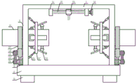
图1为本发明的主视剖面图;Fig. 1 is the front sectional view of the present invention;
图2为本发明的主视图;Fig. 2 is the front view of the present invention;
图3为本发明的图1中A处放大图;Fig. 3 is the enlarged view of place A in Fig. 1 of the present invention;
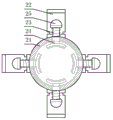
图4为本发明的固定筒里侧面剖面图;Fig. 4 is a side sectional view of the fixing cylinder of the present invention;
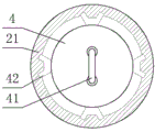
图5为本发明的固定筒外侧面剖面图;Fig. 5 is a sectional view of the outer side of the fixing cylinder of the present invention;
图6为本发明的弧形筒与弧形杆连接图;Fig. 6 is a connection diagram of the arc cylinder and the arc rod of the present invention;
图7为本发明的固定环与T形环连接图。Fig. 7 is a connection diagram of the fixing ring and the T-ring of the present invention.
图中序号:底板1、支撑底座11、电机12、主动皮带轮13、双重皮带14、从动皮带轮15、齿轮16、齿轮环17、竖板2、固定筒21、斜板22、夹持杆23、弧形夹持板24、夹持球25、铰接缸26、T形环27、固定环28、弧形限位板29、横板3、定位轴承座31、丝杠32、丝杠筒33、旋转把手34、伸缩缸35、电焊杆36、圆形推板4、U形把手41、V形滑块42、电推缸43、连接杆44、扩张杆45、弧形杆46、弧形筒47。Serial numbers in the figure:
具体实施方式Detailed ways
下面将结合本发明实施例中的附图,对本发明实施例中的技术方案进行清楚、完整地描述,显然,所描述的实施例仅仅是本发明一部分实施例,而不是全部的实施例。The following will clearly and completely describe the technical solutions in the embodiments of the present invention with reference to the accompanying drawings in the embodiments of the present invention. Obviously, the described embodiments are only some, not all, embodiments of the present invention.
实施例一:为实现短钢管夹持固定牢固及同轴焊接方便的目的,本实施例提供了具有多级调节夹持机构的塔吊管道焊接机具,参见图1-7,具有多级调节夹持机构的塔吊管道焊接机具,包括底板1、夹持组件、扩张组件、驱动机构、焊接机构,所述底板1为水平横向放置的矩形板状,所述底板1的底面四个拐角处均设有支撑底座11,所述底板1的顶面两侧设有一对竖向对称固接的竖板2,每块所述竖板2的中部均横向开设有通孔,每个所述通孔内均安装有固定轴承环,每个所述固定轴承环内均横向插设有固定贯穿的固定筒21,每个所述固定筒21的里端部均安装有夹持组件,每个所述固定筒21的外端部均安装有扩张组件,每块所述竖板2的底部均安装有驱动机构,两块所述竖板2的顶部之间设有横向放置的横板3,所述横板3的两端分别与两块竖板2的顶端固接,所述横板3的底面设有焊接机构。Embodiment 1: In order to achieve the purpose of firmly clamping and fixing short steel pipes and facilitating coaxial welding, this embodiment provides a tower crane pipe welding machine tool with a multi-level adjustment clamping mechanism, see Figure 1-7, with multi-level adjustment clamping The tower crane pipeline welding equipment of the mechanism includes a
在本发明中,所述夹持组件包括夹持杆23、弧形夹持板24、斜板22、铰接缸26,所述固定筒21的里端部外侧壁上均匀开设有四个夹持通孔,每个所述夹持通孔内均插设有滑动贯穿的夹持杆23,位于固定筒21内在每根夹持杆23的里端均设有弧形夹持板24,每块所述弧形夹持板24的里侧面均铺设有橡胶夹持垫,位于固定筒21的外侧在每根夹持杆23的外端均设有夹持球25,且在每根夹持杆23的外段上均套设有夹持弹簧,位于夹持杆23里侧的位置在固定筒21的里端部外侧壁上均匀设有四座T形铰接座,每座所述T形铰接座的外侧面均通过销轴与斜板22活动铰接,每块所述斜板22均斜向压在对应的夹持球25上,位于四块斜板22的外侧在固定筒21的里端部上套设有固定环28,所述固定环28的内侧壁上均匀设有四块弧形限位板29,且每块所述斜板22均斜向卡合在相邻的两块弧形限位板29之间,所述固定环28的外侧套设有T形环27,所述T形环27的里侧面套设有连接轴承环,且所述固定环28的外侧壁固接在连接轴承环内,所述竖板2的里侧面上下两端设有一对活动铰接的铰接缸26,铰接缸26的型号为LSH-064,两个所述铰接缸26的铰接杆端部分别与T形环27的上下两端活动铰接;通过夹持组件的配合使用,控制铰接缸26的铰接杆通过T形环27带动固定环28向里推进,带动斜板22沿着弧形限位板29之间的间隙进行收缩,带动斜板22压向夹持球25及夹持杆23,带动弧形夹持板24及橡胶夹持垫卡合固定在管道的中部,从而使得管道的中部由外而内进行夹持固定。In the present invention, the clamping assembly includes a clamping
在本发明中,所述驱动机构包括电机12、双重皮带14、齿轮环17,所述竖板2的外侧面底部凹陷有电机槽,所述电机槽内安装有输出端朝外的电机12,电机12的型号为YX3-112M-4,所述电机12的电机轴端部套设有同轴联接的主动皮带轮13,所述主动皮带轮13与从动皮带轮15之间通过双重皮带14传动连接,所述双重皮带14的两端分别套设在主动皮带轮13、从动皮带轮15上,位于电机槽与通孔之间在竖板2的外侧面凹陷有联动轴承,所述联动轴承内插设有联动轴,所述联动轴的外端部套设有同轴联接的从动皮带轮15,所述联动轴的中部套设有齿轮16,位于齿轮16对应的位置在固定筒21的外端部上套设有同轴转动的齿轮环17,所述齿轮环17的外齿牙与齿轮16的外齿牙啮合连接;通过对驱动机构的配合使用,控制电机12的电机轴带动主动皮带轮13缓慢转动,通过双重皮带14传动连接的方式带动从动皮带轮15及联动轴进行同步转动,进而带的齿轮16配合齿轮环17进行啮合转动,进而带动固定筒21绕着固定轴承缓慢转动,进而带动固定环28绕着连接轴承环同步转动,方便了对不同直径的管道进行同轴同速度的旋转。In the present invention, the drive mechanism includes a
在本发明中,所述焊接机构包括丝杠32、丝杠筒33、伸缩缸35、电焊杆36,所述横板3的底面中部设有一对定位轴承座31,每座所述定位轴承座31内均安装有定位轴承,两个所述定位轴承之间设有横向放置的丝杠32,所述丝杠32的两端分别插设在对应的定位轴承内,所述丝杠32的一端贯穿对应的定位轴承座31并套设有旋转把手34,所述丝杠32的中部套设有螺旋连接的丝杠筒33,位于两个定位轴承座之间在横板3的底面设有横向固接的T形滑轨,所述T形滑轨的底面中部卡合有滑动连接的U形滑块,且所述U形滑块的底面与丝杠筒33的顶面固接,所述丝杠筒33的底面设有安装座,所述安装座的底面设有输出端朝下的伸缩缸35,伸缩缸35的型号为CPMT1-2M,所述伸缩缸35的伸缩杆端部设有绝缘块,所述绝缘块的底面安装有电焊杆36;通过焊接机构的配合使用,转动旋转把手34带动丝杠32配合丝杠筒33进行螺旋转动,进而带动U形滑块沿着T形滑轨横向滑动,方便了带动伸缩缸35及电焊杆36移动至焊接位置处,控制伸缩缸35的伸缩杆带动电焊杆36伸长,方便了对两个管道的焊接位置进行点焊。In the present invention, the welding mechanism includes a
实施例二:为实现更好的夹持固定效果,在本实施例中,所述扩张组件包括圆形推板4、电推缸43、扩张杆45、弧形筒47,所述固定筒21的内侧壁外端设有滑动连接的圆形推板4,所述圆形推板4的里侧面中部凹陷有电推缸槽,所述电推缸槽内安装有输出端朝内的电推缸43,电推缸43的型号为MQ-TA-01,位于电推缸槽的外侧在圆形推板4的里侧面均匀设有三根活动铰接的扩张杆45,所述电推缸43的电推杆端部设有扩张块,所述扩张块的外侧面均匀设有三根活动铰接的连接杆44,每根所述连接杆44的外端均与对应的扩张杆45的中部活动铰接,每根所述扩张杆45的外端均设有弧形筒47,且三个所述弧形筒47呈圆形状排列,每根所述弧形筒47的外侧面均设有扩张软垫,每个所述弧形筒47内中部均设有连接弹簧,相邻的两个弧形筒47之间设有弧形杆46,每根所述弧形杆46的外端均滑动插设在对应的弧形筒47的端口内并与连接弹簧固接;通过扩张组件的配合使用,控制电推缸43的电推杆缩短,通过扩张块带动连接杆44向外移动,带动扩张杆45及弧形筒47沿着弧形杆47扩张,进而带动扩张软垫分别对管道里侧的内径进行扩张固定,从而使得管道的外端由内而外进行扩张夹持固定;其余结构同实施例一;Embodiment 2: In order to achieve a better clamping and fixing effect, in this embodiment, the expansion assembly includes a
实施例三:在实施例二中,还存在的两个管道接触面拼接不便的问题问题,因此,在实施例一的基础上本实施例还包括:Embodiment 3: In Embodiment 2, there is also the problem of inconvenient splicing of the two pipe contact surfaces. Therefore, on the basis of
在本发明中,所述固定筒21的内侧壁外端均匀凹陷有四个V形滑槽,V形滑槽的长度为固定筒21的一半,所述圆形推板4的外边沿均匀设有四块V形滑块42,且每块所述V形滑块42均滑动卡合在对应的V形滑槽内,所述圆形推板4的外侧面中部设有U形把手41;握住U形把手41并推动圆形推板4向内移动,带动V形滑块42沿着对应的V形滑槽滑动,进而推动对应一侧的管道向中间靠拢,从而使得两根管道焊接接触面相互抵紧。In the present invention, four V-shaped slide grooves are evenly recessed at the outer end of the inner side wall of the fixed
实施例四:在本实施例中,本发明还提出了具有多级调节夹持机构的塔吊管道焊接机具的操作方法,包括以下步骤:Embodiment 4: In this embodiment, the present invention also proposes an operation method of a tower crane pipeline welding machine with a multi-stage adjustment clamping mechanism, including the following steps:
步骤一,电机12、铰接缸26、伸缩缸35、电推缸43分别通过电源线与外接电源电性连接,并把两段待焊接且直径不同的管道分别插设在两个固定筒21的里端口内,使得每个管道的里端口分别套设在弧形筒47的外侧上;
步骤二,控制电推缸43的电推杆缩短,通过扩张块带动连接杆44向外移动,在铰接作用的配合下,带动扩张杆45的外端呈三角扩张开状,进而带动弧形筒47沿着弧形杆46扩张,使得连接弹簧被拉伸变形,进而带动扩张软垫分别对管道里侧的内径进行扩张固定,从而使得管道的外端由内而外进行扩张夹持固定;同时,握住U形把手41并推动圆形推板4向内移动,带动V形滑块42沿着对应的V形滑槽滑动,进而推动对应一侧的管道向中间靠拢,从而使得两根管道接触面相互抵紧;Step 2: Control the electric push rod of the electric push cylinder 43 to shorten, drive the connecting
步骤三,控制铰接缸26的铰接杆伸长,在铰接作用的配合下,通过T形环27带动固定环28向里推进,带动斜板22沿着弧形限位板29之间的间隙进行收缩,带动斜板22压向夹持球25及夹持杆23,带动夹持弹簧被压缩变形,带动弧形夹持板24及橡胶夹持垫卡合固定在管道的中部,从而使得管道的中部由外而内进行夹持固定;Step 3: Control the extension of the articulated rod of the articulated cylinder 26. With the cooperation of the articulated action, the T-shaped
步骤四,通过转动旋转把手34带动丝杠32配合丝杠筒33进行螺旋转动,进而带动U形滑块沿着T形滑轨横向滑动,带动伸缩缸35及电焊杆36移动至两个管道焊接位置处,控制伸缩缸35的伸缩杆缓慢伸长,进而带动电焊杆36对两个管道焊接位置顶部进行点焊;
步骤五,控制电机12的电机轴带动主动皮带轮13缓慢转动,通过双重皮带14传动连接的方式带动从动皮带轮15及联动轴进行同步转动,进而带的齿轮16配合齿轮环17进行啮合转动,进而带动固定筒21绕着固定轴承缓慢转动,进而带动固定环28绕着连接轴承环同步转动,从而带动两个管道进行缓慢转动,继续通过电焊杆36进行电焊工作,待点焊工作完毕后,对管道焊接位置进行全面焊接工作,焊接完毕后,松开管道夹持的位置,并取出焊好的加工件即可。Step five, the motor shaft of the
本发明通过各机构组件的配合使用,解决了不同直径的短钢管焊接同轴度旋转不便及夹持过程中稳定性差的问题,且整体操作步骤简单,通过对短钢管的两端进行内外双重夹持固定,增加了短钢管夹持过程的稳定性,方便了对不同直径的短钢管进行同轴同速度的旋转,提高了不同直径的短钢管焊接效率。The present invention solves the problems of inconvenient rotation of short steel pipes with different diameters due to welding coaxiality and poor stability in the clamping process through the cooperative use of various mechanism components, and the overall operation steps are simple. The clamp is fixed, which increases the stability of the short steel pipe clamping process, facilitates the coaxial and same speed rotation of short steel pipes with different diameters, and improves the welding efficiency of short steel pipes with different diameters.
以上所述,仅为本发明较佳的具体实施方式,但本发明的保护范围并不局限于此,任何熟悉本技术领域的技术人员在本发明揭露的技术范围内,根据本发明的技术方案及其发明构思加以等同替换或改变,都应涵盖在本发明的保护范围之内。The above is only a preferred embodiment of the present invention, but the scope of protection of the present invention is not limited thereto, any person familiar with the technical field within the technical scope disclosed in the present invention, according to the technical solution of the present invention Any equivalent replacement or change of the inventive concepts thereof shall fall within the protection scope of the present invention.
Claims (6)
Priority Applications (1)
| Application Number | Priority Date | Filing Date | Title |
|---|---|---|---|
| CN202110338995.2A CN113182763B (en) | 2021-03-30 | 2021-03-30 | Tower crane pipeline welding machine tool with multistage adjusting clamping mechanism and operation method thereof |
Applications Claiming Priority (1)
| Application Number | Priority Date | Filing Date | Title |
|---|---|---|---|
| CN202110338995.2A CN113182763B (en) | 2021-03-30 | 2021-03-30 | Tower crane pipeline welding machine tool with multistage adjusting clamping mechanism and operation method thereof |
Publications (2)
| Publication Number | Publication Date |
|---|---|
| CN113182763A CN113182763A (en) | 2021-07-30 |
| CN113182763B true CN113182763B (en) | 2023-05-12 |
Family
ID=76974663
Family Applications (1)
| Application Number | Title | Priority Date | Filing Date |
|---|---|---|---|
| CN202110338995.2A Active CN113182763B (en) | 2021-03-30 | 2021-03-30 | Tower crane pipeline welding machine tool with multistage adjusting clamping mechanism and operation method thereof |
Country Status (1)
| Country | Link |
|---|---|
| CN (1) | CN113182763B (en) |
Families Citing this family (19)
| Publication number | Priority date | Publication date | Assignee | Title |
|---|---|---|---|---|
| CN114083223B (en) * | 2021-12-08 | 2022-07-08 | 江苏沪云激光设备有限公司 | Laser welding equipment with tight counterpoint mechanism in tight top of pipeline inner circle |
| CN114227033B (en) * | 2021-12-20 | 2023-01-03 | 江苏金禹激光智能装备有限公司 | Auxiliary supporting device of laser pipe cutting machine for machining large-diameter pipes |
| CN114393327A (en) * | 2022-03-07 | 2022-04-26 | 山东信息职业技术学院 | A machined pipe cutting device |
| CN115070284A (en) * | 2022-07-19 | 2022-09-20 | 兴化市天泰合金制品科技有限公司 | Automatic welding equipment for alloy pipe fittings |
| CN115213607A (en) * | 2022-08-16 | 2022-10-21 | 金利分 | A thick-walled beam-column welding process for bridge engineering equipment |
| CN115740946B (en) * | 2022-12-01 | 2023-06-27 | 山东晟博安装工程有限公司 | Petrochemical engineering pipeline installation and welding auxiliary structure and application method thereof |
| CN115673632B (en) * | 2022-12-30 | 2023-03-17 | 新乡职业技术学院 | Industrial furnace shell welding device |
| CN116237702A (en) * | 2023-02-16 | 2023-06-09 | 华能伊敏煤电有限责任公司 | Auxiliary component for heat dissipation fin welding |
| CN116275753B (en) * | 2023-05-08 | 2024-04-12 | 温州车舟汽车部件有限公司 | Anti-offset welding device for engine cooling fan machining |
| CN116441839B (en) * | 2023-06-14 | 2023-08-22 | 艾瑞(成都)排放控制技术有限公司 | End cone welding fixture |
| CN116713689A (en) * | 2023-08-08 | 2023-09-08 | 江苏顺驰管业有限公司 | Butt welding device for safe processing of welded pipe |
| CN117046841A (en) * | 2023-08-19 | 2023-11-14 | 衢州杭氧特种气体有限公司 | A kind of ultra-clean gas bottle processing method |
| CN117020445B (en) * | 2023-10-08 | 2024-02-09 | 江苏泰汇不锈钢有限公司 | Stainless steel laser cutting device |
| CN117961387B (en) * | 2024-03-29 | 2024-05-28 | 上海飞挺管业制造有限公司 | Quick vertical welding device for bent pipe |
| CN118060805B (en) * | 2024-04-10 | 2024-09-17 | 湖北省建工工业设备安装有限公司 | Pressure pipeline welding device |
| CN118809079A (en) * | 2024-09-18 | 2024-10-22 | 南通科兴石墨设备有限公司 | A graphite heat exchanger installation welding device and method |
| CN118848859B (en) * | 2024-09-26 | 2024-12-10 | 常州金纬国胜管道设备有限公司 | A positioning clamping device and method for producing and processing double-wall corrugated pipes |
| CN119238029B (en) * | 2024-12-04 | 2025-02-28 | 广州乐航电子科技有限公司 | Automatic production welding equipment for air conditioner |
| CN121324478B (en) * | 2025-12-11 | 2026-04-07 | 西安石油大学 | On-line monitoring device for continuous transportation of hydrogen-doped natural gas pipeline |
Citations (10)
| Publication number | Priority date | Publication date | Assignee | Title |
|---|---|---|---|---|
| CN107877075A (en) * | 2017-12-12 | 2018-04-06 | 范满香 | A kind of Pipe installing jointing ring flange automatic welding handles all-in-one |
| CN207606450U (en) * | 2017-12-12 | 2018-07-13 | 上海邦临机械设备有限公司 | A kind of Pipe installing jointing ring flange automatic welding processing all-in-one machine |
| CN207873660U (en) * | 2017-12-28 | 2018-09-18 | 资阳晨风机电有限公司 | A kind of pipe fitting turning attachment |
| CN109317914A (en) * | 2018-10-24 | 2019-02-12 | 张晓锋 | Equipment and exhaust tube splicing process is welded and fixed in a kind of curved connect of exhaust funnel of motorcycle |
| CN111189776A (en) * | 2020-01-14 | 2020-05-22 | 大同新成新材料股份有限公司 | Online abrasion detection tool for intelligent carbon sliding plate and detection method thereof |
| CN111331274A (en) * | 2020-04-09 | 2020-06-26 | 朱增 | Pipe fitting welding process intelligent machine |
| CN111390477A (en) * | 2020-04-30 | 2020-07-10 | 常州工学院 | A size-adjustable rectangular frame electric clamping auxiliary welding tool |
| CN111438406A (en) * | 2020-02-24 | 2020-07-24 | 重庆市隆桓机械有限公司 | Gear grinding frock clamp of high accuracy |
| CN211162224U (en) * | 2019-11-26 | 2020-08-04 | 宁波百华数控机械有限公司 | Beveling machine |
| CN212626843U (en) * | 2020-06-04 | 2021-02-26 | 合肥劲力供电设备有限责任公司 | A portable cable cuts instrument for electric power engineering |
Family Cites Families (15)
| Publication number | Priority date | Publication date | Assignee | Title |
|---|---|---|---|---|
| KR20140001319U (en) * | 2012-08-23 | 2014-03-06 | 현대중공업 주식회사 | Overhead type auto welding device attaching arc blocking panel |
| CN104148868B (en) * | 2014-08-01 | 2016-05-25 | 成都艾格科技有限责任公司 | Be applicable to non-some fixed pattern Welding machine of circumferential weld of inner support outer hoop of single face welding and double face shaping |
| CN105485425B (en) * | 2015-11-26 | 2019-03-22 | 天津市安维康家科技发展有限公司 | Large diameter pipeline is automatically continuously laid with Work robot and its operational method |
| CN106312627A (en) * | 2016-10-14 | 2017-01-11 | 浙江金马逊机械有限公司 | Rotating feeding device capable of achieving clamping from interior of pipe end |
| CA2984297A1 (en) * | 2017-02-28 | 2018-08-28 | Gregg R. Bruinsma | Pipe end truing apparatus and method |
| CN207695935U (en) * | 2017-12-27 | 2018-08-07 | 三明市明网网络信息技术有限公司 | A kind of robot welding fixture convenient for adjusting |
| CN208929468U (en) * | 2018-08-13 | 2019-06-04 | 深圳美克激光设备有限公司 | A kind of pipe clamping device of tubing laser cutting machine |
| CN108747174A (en) * | 2018-08-28 | 2018-11-06 | 佛山迅拓奥科技有限公司 | A kind of monometallic pipe movement adjustable type welding detent mechanism |
| CN109128539B (en) * | 2018-09-19 | 2020-07-17 | 中国航空制造技术研究院 | Laser welding flexible clamping device, system and method for aluminum alloy sliding rail sleeve |
| CN209125166U (en) * | 2018-12-07 | 2019-07-19 | 深圳市龙兴盛五金塑胶有限公司 | A kind of hardware automatic welding device |
| CN210335183U (en) * | 2019-07-09 | 2020-04-17 | 天津市德重机械设备有限公司 | Automatic segmentation cutting device of crusher main shaft |
| CN110605600A (en) * | 2019-09-26 | 2019-12-24 | 浙江科贸实业有限公司 | An umbrella tensioning device |
| CN211028816U (en) * | 2019-11-21 | 2020-07-17 | 青岛星跃铁塔有限公司 | Automatic rotating device for steel structure welding |
| CN211249690U (en) * | 2019-11-25 | 2020-08-14 | 海油发展珠海管道工程有限公司 | Bimetal composite pipe end protection device |
| CN212223945U (en) * | 2020-04-15 | 2020-12-25 | 徐恒强 | Tower crane foundation device with automatic sinking function |
-
2021
- 2021-03-30 CN CN202110338995.2A patent/CN113182763B/en active Active
Patent Citations (10)
| Publication number | Priority date | Publication date | Assignee | Title |
|---|---|---|---|---|
| CN107877075A (en) * | 2017-12-12 | 2018-04-06 | 范满香 | A kind of Pipe installing jointing ring flange automatic welding handles all-in-one |
| CN207606450U (en) * | 2017-12-12 | 2018-07-13 | 上海邦临机械设备有限公司 | A kind of Pipe installing jointing ring flange automatic welding processing all-in-one machine |
| CN207873660U (en) * | 2017-12-28 | 2018-09-18 | 资阳晨风机电有限公司 | A kind of pipe fitting turning attachment |
| CN109317914A (en) * | 2018-10-24 | 2019-02-12 | 张晓锋 | Equipment and exhaust tube splicing process is welded and fixed in a kind of curved connect of exhaust funnel of motorcycle |
| CN211162224U (en) * | 2019-11-26 | 2020-08-04 | 宁波百华数控机械有限公司 | Beveling machine |
| CN111189776A (en) * | 2020-01-14 | 2020-05-22 | 大同新成新材料股份有限公司 | Online abrasion detection tool for intelligent carbon sliding plate and detection method thereof |
| CN111438406A (en) * | 2020-02-24 | 2020-07-24 | 重庆市隆桓机械有限公司 | Gear grinding frock clamp of high accuracy |
| CN111331274A (en) * | 2020-04-09 | 2020-06-26 | 朱增 | Pipe fitting welding process intelligent machine |
| CN111390477A (en) * | 2020-04-30 | 2020-07-10 | 常州工学院 | A size-adjustable rectangular frame electric clamping auxiliary welding tool |
| CN212626843U (en) * | 2020-06-04 | 2021-02-26 | 合肥劲力供电设备有限责任公司 | A portable cable cuts instrument for electric power engineering |
Non-Patent Citations (2)
| Title |
|---|
| 冯一辉 ; 王康 ; 王剑锋 ; .长距离大口径钢顶管施工关键技术.中国市政工程.2010,(03),全文. * |
| 高洁 ; .压力钢管制造安装质量与成本控制因素探讨.冶金管理.2020,(05),全文. * |
Also Published As
| Publication number | Publication date |
|---|---|
| CN113182763A (en) | 2021-07-30 |
Similar Documents
| Publication | Publication Date | Title |
|---|---|---|
| CN113182763A (en) | Tower crane pipeline welding tool with multi-stage adjusting and clamping mechanism and operation method thereof | |
| CN114406544B (en) | A pipeline full-position automatic welding machine | |
| CN115156786A (en) | Steel construction field welding device for bridge construction | |
| CN107097033B (en) | A kind of 90 ° of elbow internal wall built-up welding displacement devices | |
| CN116984782B (en) | A design positioning device and positioning method for a welding operation platform | |
| CN216370794U (en) | Welding device for bent steel pipe | |
| CN206912595U (en) | A kind of 90 ° of elbow internal wall built-up welding displacement devices | |
| CN221658432U (en) | A steel structure butt welding adjustment device | |
| CN219966957U (en) | Welding device for metal corrugated pipe | |
| CN220239844U (en) | Y-shaped three-way copper pipe necking machining device | |
| CN119347059A (en) | A guide tube submerged arc welding positioning device and process thereof | |
| CN208513891U (en) | A kind of welder for elevator production | |
| CN112872677B (en) | Device for welding steel structure | |
| CN218983796U (en) | Steel pipe clamp | |
| CN118616955A (en) | A multi-degree-of-freedom adjustable internal and external annular seam welding mechanism for circular pipe fittings | |
| CN214868344U (en) | Semi-automatic welding pipe horizontal alignment device | |
| CN212122232U (en) | A welding auxiliary tool for tubular workpiece | |
| CN114473158A (en) | Industrial automatic electric arc welding workbench | |
| CN222643655U (en) | Steel pipe jointing equipment | |
| CN222890735U (en) | Sheet metal butt welding frock | |
| CN220902347U (en) | Steel structure welding positioner | |
| CN220330460U (en) | Welded pipe butt welding support | |
| CN120133819B (en) | Multidirectional positioning type metal part welding equipment and method | |
| CN220921419U (en) | Auxiliary welding device for pipe fittings | |
| CN222176548U (en) | A welding flip device |
Legal Events
| Date | Code | Title | Description |
|---|---|---|---|
| PB01 | Publication | ||
| PB01 | Publication | ||
| SE01 | Entry into force of request for substantive examination | ||
| SE01 | Entry into force of request for substantive examination | ||
| GR01 | Patent grant | ||
| GR01 | Patent grant | ||
| CP03 | Change of name, title or address | ||
| CP03 | Change of name, title or address |
Address after: No. 002, Eshe Village, Jiade Township, Yaodu District, Linfen City, Shanxi Province (with multiple locations) Patentee after: Shanxi Huayao Heavy Industry Co.,Ltd. Country or region after: China Address before: No. 002, Ejin Village, Jiade Township, Yaodu District, Linfen City, Shanxi Province Patentee before: Shanxi Huayao Heavy Industry Co.,Ltd. Country or region before: China |