CN113161891A - Terminal box with dampproofing function - Google Patents
Terminal box with dampproofing function Download PDFInfo
- Publication number
- CN113161891A CN113161891A CN202110268373.7A CN202110268373A CN113161891A CN 113161891 A CN113161891 A CN 113161891A CN 202110268373 A CN202110268373 A CN 202110268373A CN 113161891 A CN113161891 A CN 113161891A
- Authority
- CN
- China
- Prior art keywords
- door
- box
- fixedly connected
- terminal box
- waterproof
- Prior art date
- Legal status (The legal status is an assumption and is not a legal conclusion. Google has not performed a legal analysis and makes no representation as to the accuracy of the status listed.)
- Pending
Links
Images



Classifications
-
- H—ELECTRICITY
- H02—GENERATION; CONVERSION OR DISTRIBUTION OF ELECTRIC POWER
- H02B—BOARDS, SUBSTATIONS OR SWITCHING ARRANGEMENTS FOR THE SUPPLY OR DISTRIBUTION OF ELECTRIC POWER
- H02B1/00—Frameworks, boards, panels, desks, casings; Details of substations or switching arrangements
- H02B1/26—Casings; Parts thereof or accessories therefor
- H02B1/46—Boxes; Parts thereof or accessories therefor
-
- H—ELECTRICITY
- H02—GENERATION; CONVERSION OR DISTRIBUTION OF ELECTRIC POWER
- H02B—BOARDS, SUBSTATIONS OR SWITCHING ARRANGEMENTS FOR THE SUPPLY OR DISTRIBUTION OF ELECTRIC POWER
- H02B1/00—Frameworks, boards, panels, desks, casings; Details of substations or switching arrangements
- H02B1/26—Casings; Parts thereof or accessories therefor
- H02B1/28—Casings; Parts thereof or accessories therefor dustproof, splashproof, drip-proof, waterproof or flameproof
-
- H—ELECTRICITY
- H02—GENERATION; CONVERSION OR DISTRIBUTION OF ELECTRIC POWER
- H02B—BOARDS, SUBSTATIONS OR SWITCHING ARRANGEMENTS FOR THE SUPPLY OR DISTRIBUTION OF ELECTRIC POWER
- H02B1/00—Frameworks, boards, panels, desks, casings; Details of substations or switching arrangements
- H02B1/56—Cooling; Ventilation
- H02B1/565—Cooling; Ventilation for cabinets
Landscapes
- Engineering & Computer Science (AREA)
- Power Engineering (AREA)
- Photovoltaic Devices (AREA)
Abstract
The invention discloses a terminal box with a damp-proof function, which comprises a terminal box, wherein the middle part of the left side of the terminal box is fixedly connected with a heat dissipation mechanism, the bottom of the terminal box is fixedly connected with a lifting base mechanism, the middle of the top of the terminal box is fixedly connected with a supporting rod, the top end of the supporting rod is fixedly connected with a solar panel, the inner wall of the bottom of the terminal box, which is close to the right side, is fixedly connected with a storage battery, the middle of the bottom of the terminal box is fixedly connected with a rainwater detector, and the bottom of the terminal box, which is close to the left side, is fixedly connected with an intelligent control main board. This terminal box with dampproofing function is provided with waterproof roof and weather shield to all spray the waterproof anticorrosive material at the surface of box, waterproof roof, weather shield, first chamber door and second chamber door, be provided with lifting base mechanism cooperation rain detector, prevent that the rainwater from getting into the inside moisture of box, the inside silica gel drier that can reuse of cooperation prevents to cause the inside electron device of box to damage.
Description
Technical Field
The invention relates to the technical field of electrical equipment, in particular to a terminal box with a moisture-proof function.
Background
The wiring terminal box is a switching construction circuit, mark branch circuit, provide convenient interface arrangement for wiring and inspection line, under some circumstances, be convenient for construction and debugging, can install some comparatively special and install and set up comparatively regular products in the wiring terminal box like short circuit isolator, binding post is exactly an accessory product that is used for realizing electrical connection, the category of connector is divided into in the industry, along with industrial automation degree is higher and the industrial control requires stricter and stricter, accurate, binding post's quantity rises gradually, along with the development of electron trade, binding post's application range is more and more, and the kind is also more and more.
The existing terminal box is poor in moisture-proof effect, an electrical element inside the terminal box is easily damaged, the terminal box is not convenient to use by a user, the practicability of the terminal box is reduced, meanwhile, the existing terminal box inner space pin is sealed, heat dissipation of internal electronic equipment is not facilitated, and the internal electronic equipment can be damaged due to overhigh temperature in hot weather.
Disclosure of Invention
The present invention is directed to a terminal box with moisture-proof function, so as to solve the problems in the background art.
In order to achieve the purpose, the invention provides the following technical scheme: the utility model provides a terminal box with dampproofing function, includes the terminal box, terminal box left side middle part fixedly connected with heat dissipation mechanism, terminal bottom of the case portion fixedly connected with lifting pedestal mechanism, the fixedly connected with bracing piece in the middle of the terminal box top, bracing piece top fixedly connected with solar panel, the bottom inner wall of terminal box is close to right side fixedly connected with battery, fixedly connected with rainwater detection instrument in the middle of the terminal bottom of the case portion, the bottom of terminal box is close to left side fixedly connected with intelligent control mainboard, fixedly connected with drying mechanism in the middle of the top inner wall of terminal box.
The terminal box comprises a box body, a waterproof box top, a rain baffle, a vent, a perforated partition plate, a first box door, a second box door, a door handle and a door lock, wherein the box body is fixedly connected to the bottom of the waterproof box top, the waterproof box top is fixedly connected to the lower end of a supporting rod, the rain baffle is fixedly connected to the left side of the box body at a position close to the top, the vent is arranged on the right side of the box body, the perforated partition plate is fixedly connected to the inner walls of the left side and the right side of the box body at a position close to the bottom, the first box door is arranged on the upper front portion of the box body, the second box door is arranged on the lower front portion of the box body, the door handle is fixedly connected to the middle portions of the front of the first box door and the front of the second box door, and the door lock is fixedly connected to the middle portions of the front of the first box door and the front of the second box door.
Further, heat dissipation mechanism includes ventilation pipe, dust screen, dead lever and fan, ventilation pipe fixed connection is in the left side of box, dust screen fixed connection is in the inner wall left side of ventilation pipe, dead lever fixed connection is in the inner wall top and the bottom that ventilation pipe and dust screen are adjacent, fan fixed connection is in the middle part of dead lever.
Further, the lifting base mechanism comprises lifting rods, a fixing plate, fixing holes and fixing bolts, the number of the lifting rods is four, the lifting rods are fixedly connected to the bottom of the box body and are close to the corners all around, the fixing plate is fixedly connected to the bottom end of the lifting rods, the number of the fixing holes is eight and eight, the fixing holes are respectively formed in the left side and the right side of the joint of the top of the fixing plate and the four lifting rods, and the number of the fixing bolts is eight and eight, and the fixing bolts are respectively connected to the eight fixing holes in a sliding mode.
Further, frame and silica gel drier are place to drying mechanism includes connecting rod, drier, the quantity of connecting rod is two, two the equal fixed connection of connecting rod is in the top inner wall of terminal case, two the connecting rod is bilateral symmetry about being at top inner wall center, frame fixed connection is placed to the drier in the bottom of connecting rod, the drier is placed and is pegged graft in the middle of the frame top and have the silica gel drier.
Furthermore, the box body, the waterproof box top, the rain baffle, the first box door, the second box door, the door handle and the door lock are all made of stainless steel, and waterproof and anticorrosive materials are sprayed on the outer surface of the stainless steel.
Further, the first door and the second door are split doors, the number of the door handles and the number of the door locks are four, two of the door handles and the two door locks are fixedly connected to the first door, the two door handles and the two door locks are bilaterally symmetrical about the door seam of the first door split door, the other two door handles and the two door locks are fixedly connected to the second door, and the other two door handles and the two door locks are bilaterally symmetrical about the door seam of the second door split door.
Further, the material of dust screen is stainless steel material, dust screen surface spraying has waterproof anticorrosive paint spraying.
Further, solar panel and battery electric connection, the battery is electric connection with rainwater detection instrument, intelligent control mainboard, lifter and fan, intelligent control mainboard and lifter, rainwater detection instrument electric connection.
Compared with the prior art, the invention has the beneficial effects that:
1. this terminal box with dampproofing function, be provided with waterproof roof and weather shield, and at the box, waterproof roof, the weather shield, the equal spraying of surface of first chamber door and second chamber door has waterproof anticorrosive material, guarantee that the device can not corroded by the rainwater, be provided with lifting base mechanism cooperation rain detector, when rainwater ponding is more when being monitored by rain detector, the inside lifter of lifting base mechanism can lift up the terminal box, keep presenting certain height with ground, prevent that the rainwater from getting into the inside moisture of box, the inside silica gel drier that can reuse of cooperation, prevent to cause the inside electron device of box to damage.
2. This terminal box with dampproofing function is provided with heat dissipation mechanism and vent, and the inside fan of start heat dissipation mechanism can be with inside the outside cold air suction box, simultaneously because the space size of box inside is unchangeable, the inside hot-air of box can be followed the vent and discharged to take away the heat that produces when the inside electronic device of box moves, protect the electronic device and can not destroy because of the high temperature.
3. This terminal box with dampproofing function is provided with solar panel at terminal box top, can charge for inside battery to drive the operation of whole device, make whole device need not to connect external power source, realize self-sufficiency, accord with the environmental protection theory of advocating by the country.
Drawings
In order to make the objects, technical solutions and advantages of the present invention more apparent, the present invention will be further described in detail with reference to the accompanying drawings, in which:
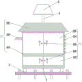
FIG. 1 is a schematic front view of the overall structure of the present invention;
FIG. 2 is a schematic front sectional view of the overall structure of the present invention;
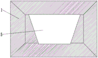
FIG. 3 is a schematic top view of the overall structure of the present invention;
FIG. 4 is a schematic view of a heat dissipation mechanism according to the present invention;
FIG. 5 is a schematic top view of a lifting base mechanism of the present invention.
In the figure: 1. a terminal box; 101. a box body; 102. a waterproof box top; 103. a rain shield; 104. a vent; 105. a perforated partition plate; 106. a first door; 107. a second door; 108. a door handle; 109. a door lock; 2. a heat dissipation mechanism; 201. a vent pipe; 202. a dust screen; 203. fixing the rod; 204. a fan; 3. a lifting base mechanism; 301. a lifting rod; 302. a fixing plate; 303. a fixing hole; 304. a fixing bolt; 4. a support bar; 5. a solar panel; 6. a storage battery; 7. a rain detector; 8. an intelligent control mainboard; 9. a drying mechanism; 901. a connecting rod; 902. a desiccant placement rack; 903. a silica gel desiccant.
Detailed Description
The technical solutions in the embodiments of the present invention will be clearly and completely described below with reference to the drawings in the embodiments of the present invention, and it is obvious that the described embodiments are only a part of the embodiments of the present invention, and not all of the embodiments. All other embodiments, which can be derived by a person skilled in the art from the embodiments given herein without making any creative effort, shall fall within the protection scope of the present invention.
In the present invention, unless otherwise expressly stated or limited, the terms "mounted," "connected," "secured," and the like are to be construed broadly and can, for example, be fixedly connected, detachably connected, or integrally formed; can be mechanically or electrically connected; either directly or indirectly through intervening media, either internally or in any other relationship. The specific meanings of the above terms in the present invention can be understood by those skilled in the art according to specific situations.
As shown in the figure, the terminal box with the moisture-proof function comprises a terminal box 1, wherein the middle part of the left side of the terminal box 1 is fixedly connected with a heat dissipation mechanism 2, the bottom of the terminal box 1 is fixedly connected with a lifting base mechanism 3, the middle part of the top of the terminal box 1 is fixedly connected with a support rod 4, the top end of the support rod 4 is fixedly connected with a solar panel 5, the inner wall of the bottom of the terminal box 1, which is close to the right side, is fixedly connected with a storage battery 6, the middle part of the bottom of the terminal box 1 is fixedly connected with a rainwater detector 7, the bottom of the terminal box 1, which is close to the left side, is fixedly connected with an intelligent control mainboard 8, the solar panel 5 is electrically connected with the storage battery 6, the rainwater detector 7, the intelligent control mainboard 8, a lifting rod 301 and a fan 204 are electrically connected, the intelligent control mainboard 8 is electrically connected with the lifting rod 301 and the rainwater detector 7, and a drying mechanism 9 is fixedly connected with the middle part of the inner wall of the top of the terminal box 1, be provided with solar panel 5 at 1 top of terminal box, can charge for inside battery 6 to drive the operation of whole device, make whole device need not to connect external power source, realize self-sufficiency, accord with the environmental protection theory that the country advocated.
The terminal box 1 comprises a box body 101, a waterproof box top 102, a rain baffle 103, a vent 104, a perforated partition plate 105, a first box door 106, a second box door 107, a door handle 108 and a door lock 109, wherein the box body 101 is fixedly connected to the bottom of the waterproof box top 102, the waterproof box top 102 is fixedly connected to the lower end of a supporting rod 4, the rain baffle 103 is fixedly connected to the left side of the box body 101 near the top, the vent 104 is arranged on the right side of the box body 101, the perforated partition plate 105 is fixedly connected to the inner walls of the left side and the right side of the box body 101 near the bottom, the first box door 106 is arranged on the upper front side of the box body 101, the second box door 107 is arranged on the lower front side of the box body 101, the door handle 108 is fixedly connected to the middle parts of the front sides of the first box door 106 and the second box door 107, the door lock 109 is fixedly connected to the middle parts of the front sides of the first box door 106 and the second box door 107, the first box door 106 and the second door 107 are split doors, and the door handles 108 and the door locks 109 are four, wherein two door handles 108 and a door lock 109 are fixedly connected to a first door 106, two door handles 108 and a door lock 109 are bilaterally symmetrical about the split door seam of the first door 106, the other two door handles 108 and a door lock 109 are fixedly connected to a second door 107, the other two door handles 108 and a door lock 109 are bilaterally symmetrical about the split door seam of the second door 106, the box body 101, the waterproof box 102, the rain shield 103, the first door 106, the second door 107, the door handles 108 and the door lock 109 are all made of stainless steel, the outer surfaces of the stainless steel are all coated with waterproof and anticorrosive materials, a waterproof box top 102 and a rain shield 103 are arranged, and the outer surfaces of the box body 101, the waterproof box top 102, the rain shield 103, the first door 106 and the second door 107 are all coated with waterproof and anticorrosive materials to ensure that the device is not corroded by rainwater, a lifting base mechanism 3 is arranged to be matched with a rainwater detector 7, when rainwater ponding is more monitored by rain detector 7, the inside lifter 301 of lifting pedestal mechanism 3 can lift terminal box 1, keeps presenting certain height with ground, prevents that the rainwater from getting into box 101 inside and weing, and the inside silica gel drier 903 that can reuse of cooperation prevents to cause the inside electron device of box 101 to damage.
The heat dissipation mechanism 2 comprises a ventilation pipe 201, a dust screen 202, a fixed rod 203 and a fan 204, the ventilation pipe 201 is fixedly connected to the left side of the box body 101, the dust screen 202 is fixedly connected to the left side of the inner wall of the ventilation pipe 201, the dust screen 202 is made of stainless steel, waterproof, anticorrosion and spray paint is sprayed on the surface of the dust screen 202, the fixed rod 203 is fixedly connected to the top and the bottom of the inner wall of the ventilation pipe 201 adjacent to the dust screen 202, the fan 204 is fixedly connected to the middle part of the fixed rod 203, the heat dissipation mechanism 2 and the ventilation opening 104 are arranged, the fan 204 in the heat dissipation mechanism 2 is started, and outside cool air can be sucked into the box body 101, meanwhile, as the size of the space inside the box body 101 is not changed, the hot air inside the box body 101 is discharged from the vent 104, therefore, heat generated when the electronic device in the box body 101 runs is taken away, and the electronic device is protected from being damaged due to overhigh temperature.
Lifting pedestal mechanism 3 includes lifter 301, fixed plate 302, fixed orifices 303 and gim peg 304, lifter 301's quantity is four, four lifter 301 fixed connection are close to the corner all around in the bottom of box 11, fixed plate 302 fixed connection is in lifter 301's bottom, the quantity of fixed orifices 303 is eight, the left and right sides of fixed plate 302 top and four lifter 301 junctions is seted up respectively to eight fixed orifices 303, the quantity of gim peg 304 is eight, eight gim peg 304 are sliding connection respectively in eight fixed orifices 303, lifting pedestal mechanism 3 can play the effect of supporting whole device, also can cooperate rain detector 7 to prevent that box 101 is inside to intake simultaneously.
When in use: the lifting base mechanism 3 of the terminal box with the moisture-proof function is fixedly connected to the ground, so that the stable operation of the device is ensured, the electronic equipment to be installed is installed into the box body 101 by opening the first box door 106, the solar panel 5 converts absorbed light energy into electric energy to be transmitted to the storage battery 6 through a transmission line, the storage battery 6 is connected with the rainwater detector 7, the intelligent control mainboard 8, the lifting rods 301 and the fan 204 through the transmission line, when the external rains, the waterproof box top 102 and the rain shield plate 103 block rainwater blown from the inclined surface, after accumulated water on the ground is detected by the rainwater detector 7, the rainwater detector 7 is timely transmitted to the intelligent control mainboard 8, the intelligent control mainboard controls the four lifting rods 301 to simultaneously lift the terminal box 1 to a certain height, so as to prevent rainwater from entering the box body 101, when the temperature in the box body 101 is overhigh, the intelligent control mainboard 8 starts the fan 204, the outside cool air of box 101 is inhaled inside box 101 to squeeze away the inside hot-air of box 101 and follow vent 104 and discharge the box 101 outside, thereby reduce the inside temperature of box 101, if the weather is moist simultaneously, result in the inside air water content of box 101 to be big, then inside repeatedly usable's silica gel drier 903 of dry mechanism 9 can absorb the inside moisture of box 101, guarantees the inside drying of box 101.
It is noted that, herein, relational terms such as first and second, and the like may be used solely to distinguish one entity or action from another entity or action without necessarily requiring or implying any actual such relationship or order between such entities or actions. Also, the terms "comprises," "comprising," or any other variation thereof, are intended to cover a non-exclusive inclusion, such that a process, method, article, or apparatus that comprises a list of elements does not include only those elements but may include other elements not expressly listed or inherent to such process, method, article, or apparatus. The term "comprising", without further limitation, means that the element so defined is not excluded from the group consisting of additional identical elements in the process, method, article, or apparatus that comprises the element.
Although embodiments of the present invention have been shown and described above, it is understood that the above embodiments are exemplary and should not be construed as limiting the present invention, and that variations, modifications, substitutions and alterations can be made in the above embodiments by those of ordinary skill in the art without departing from the principle and spirit of the present invention. Any modification, equivalent replacement, or improvement made within the spirit and principle of the present invention should be included in the protection scope of the present invention.
Claims (8)
1. The utility model provides a terminal box with dampproofing function, includes terminal box (1), its characterized in that: the middle of the left side of the terminal box (1) is fixedly connected with a heat dissipation mechanism (2), the bottom of the terminal box (1) is fixedly connected with a lifting base mechanism (3), the middle of the top of the terminal box (1) is fixedly connected with a support rod (4), the top of the support rod (4) is fixedly connected with a solar panel (5), the inner wall of the bottom of the terminal box (1) is close to the right side and is fixedly connected with a storage battery (6), the middle of the bottom of the terminal box (1) is fixedly connected with a rainwater detector (7), the bottom of the terminal box (1) is close to the left side and is fixedly connected with an intelligent control main board (8), and the middle of the inner wall of the top of the terminal box (1) is fixedly connected with a drying mechanism (9);
the terminal box (1) comprises a box body (101), a waterproof box top (102), a rain baffle plate (103), a ventilation opening (104), a perforated partition plate (105), a first box door (106), a second box door (107), a door handle (108) and a door lock (109), wherein the box body (101) is fixedly connected to the bottom of the waterproof box top (102), the waterproof box top (102) is fixedly connected to the lower end of a supporting rod (4), the rain baffle plate (103) is fixedly connected to the position, close to the top, of the left side of the box body (101), the ventilation opening (104) is arranged on the right side of the box body (101), the perforated partition plate (105) is fixedly connected to the position, close to the bottom, of the inner walls of the left side and the right side of the box body (101), the first box door (106) is arranged on the upper portion of the front of the box body (101), the second box door (107) is arranged on the lower portion of the front of the box body (101), and the door handle (108) is fixedly connected to the middle portions of the front of the first box door (106) and the second box door (107), the door lock (109) is fixedly connected to the front middle parts of the first door (106) and the second door (107).
2. The terminal box with moisture-proof function according to claim 1, wherein: heat dissipation mechanism (2) include ventilation pipe (201), dust screen (202), dead lever (203) and fan (204), ventilation pipe (201) fixed connection is in the left side of box (101), dust screen (202) fixed connection is in the inner wall left side of ventilation pipe (201), dead lever (203) fixed connection is in ventilation pipe (201) and dust screen (202) adjacent inner wall top and bottom, fan (204) fixed connection is in the middle part of dead lever (203).
3. The terminal box with moisture-proof function according to claim 1, wherein: lifting pedestal mechanism (3) include lifter (301), fixed plate (302), fixed orifices (303) and gim peg (304), the quantity of lifter (301) is four, four lifter (301) fixed connection is close to the corner all around in the bottom of box (11), fixed plate (302) fixed connection is in the bottom of lifter (301), the quantity of fixed orifices (303) is eight, eight fixed orifices (303) are seted up respectively in the left and right sides of fixed plate (302) top and four lifter (301) junctions, the quantity of gim peg (304) is eight, eight gim peg (304) sliding connection is in eight fixed orifices (303) respectively.
4. The terminal box with moisture-proof function according to claim 1, wherein: the drying mechanism (9) comprises two connecting rods (901), a drying agent placing frame (902) and silica gel drying agents (903), the two connecting rods (901) are fixedly connected to the inner wall of the top of the terminal box (1), the two connecting rods (901) are bilaterally symmetrical about the center of the inner wall of the top, the drying agent placing frame (902) is fixedly connected to the bottom end of the connecting rods (901), and the silica gel drying agents (903) are inserted in the middle of the top of the drying agent placing frame (902).
5. The terminal box with moisture-proof function according to claim 1, wherein: the box body (101), the waterproof box top (102), the rain baffle (103), the first box door (106), the second box door (107), the door handle (108) and the door lock (109) are all made of stainless steel, and waterproof and anticorrosive materials are sprayed on the outer surfaces of the stainless steel.
6. The terminal box with moisture-proof function according to claim 1, wherein: the first door (106) and the second door (107) are split doors, the number of the door handles (108) and the number of the door locks (109) are four, two of the door handles (108) and the door locks (109) are fixedly connected to the first door (106), two of the door handles (108) and the door locks (109) are bilaterally symmetrical about the split door seam of the first door (106), the other two of the door handles (108) and the door locks (109) are fixedly connected to the second door (107), and the other two of the door handles (108) and the door locks (109) are bilaterally symmetrical about the split door seam of the second door (106).
7. The terminal box with moisture-proof function according to claim 2, wherein: the material of dust screen (202) is stainless steel material, dust screen (202) surface spraying has waterproof anticorrosive paint spraying.
8. The terminal box with moisture-proof function according to claim 1, wherein: solar panel (5) and battery (6) electric connection, battery (6) and rainwater detection instrument (7), intelligent control mainboard (8), lifter (301) and fan (204) are electric connection, intelligent control mainboard (8) and lifter (301), rainwater detection instrument (7) electric connection.
Priority Applications (1)
| Application Number | Priority Date | Filing Date | Title |
|---|---|---|---|
| CN202110268373.7A CN113161891A (en) | 2021-03-12 | 2021-03-12 | Terminal box with dampproofing function |
Applications Claiming Priority (1)
| Application Number | Priority Date | Filing Date | Title |
|---|---|---|---|
| CN202110268373.7A CN113161891A (en) | 2021-03-12 | 2021-03-12 | Terminal box with dampproofing function |
Publications (1)
| Publication Number | Publication Date |
|---|---|
| CN113161891A true CN113161891A (en) | 2021-07-23 |
Family
ID=76887570
Family Applications (1)
| Application Number | Title | Priority Date | Filing Date |
|---|---|---|---|
| CN202110268373.7A Pending CN113161891A (en) | 2021-03-12 | 2021-03-12 | Terminal box with dampproofing function |
Country Status (1)
| Country | Link |
|---|---|
| CN (1) | CN113161891A (en) |
Cited By (2)
| Publication number | Priority date | Publication date | Assignee | Title |
|---|---|---|---|---|
| CN113917105A (en) * | 2021-11-01 | 2022-01-11 | 商河县天域工程技术中心 | Water environment automatic monitoring early warning equipment |
| CN115623993A (en) * | 2022-09-07 | 2023-01-20 | 东莞市哈士智能科技有限公司 | Pet water dispenser |
Citations (6)
| Publication number | Priority date | Publication date | Assignee | Title |
|---|---|---|---|---|
| CN206558913U (en) * | 2017-01-18 | 2017-10-13 | 广东亚欧电气科技有限公司 | High-voltage distribution box outside a kind of safe moisture proof formula room |
| CN207099502U (en) * | 2017-08-29 | 2018-03-13 | 程振远 | A kind of moistureproof outdoor electrical control cabinet |
| CN208016233U (en) * | 2018-04-20 | 2018-10-26 | 国家电网公司 | A kind of power communication heat-radiating dustproof device |
| CN208401366U (en) * | 2018-08-03 | 2019-01-18 | 沧州铭展电气设备有限公司 | One kind is exempted to disassemble extensible formula power distribution cabinet |
| CN210780215U (en) * | 2019-12-06 | 2020-06-16 | 扬州至德电子技术有限公司 | Small outdoor UPS power supply fixing and protecting structure |
| CN112234449A (en) * | 2020-10-10 | 2021-01-15 | 魏绍国 | Electrical equipment protective box with anticorrosion and dampproof functions |
-
2021
- 2021-03-12 CN CN202110268373.7A patent/CN113161891A/en active Pending
Patent Citations (6)
| Publication number | Priority date | Publication date | Assignee | Title |
|---|---|---|---|---|
| CN206558913U (en) * | 2017-01-18 | 2017-10-13 | 广东亚欧电气科技有限公司 | High-voltage distribution box outside a kind of safe moisture proof formula room |
| CN207099502U (en) * | 2017-08-29 | 2018-03-13 | 程振远 | A kind of moistureproof outdoor electrical control cabinet |
| CN208016233U (en) * | 2018-04-20 | 2018-10-26 | 国家电网公司 | A kind of power communication heat-radiating dustproof device |
| CN208401366U (en) * | 2018-08-03 | 2019-01-18 | 沧州铭展电气设备有限公司 | One kind is exempted to disassemble extensible formula power distribution cabinet |
| CN210780215U (en) * | 2019-12-06 | 2020-06-16 | 扬州至德电子技术有限公司 | Small outdoor UPS power supply fixing and protecting structure |
| CN112234449A (en) * | 2020-10-10 | 2021-01-15 | 魏绍国 | Electrical equipment protective box with anticorrosion and dampproof functions |
Cited By (3)
| Publication number | Priority date | Publication date | Assignee | Title |
|---|---|---|---|---|
| CN113917105A (en) * | 2021-11-01 | 2022-01-11 | 商河县天域工程技术中心 | Water environment automatic monitoring early warning equipment |
| CN113917105B (en) * | 2021-11-01 | 2022-05-03 | 山东深信节能环保科技有限公司 | A kind of water environment automatic monitoring and early warning equipment |
| CN115623993A (en) * | 2022-09-07 | 2023-01-20 | 东莞市哈士智能科技有限公司 | Pet water dispenser |
Similar Documents
| Publication | Publication Date | Title |
|---|---|---|
| CN209249989U (en) | A kind of distribution box for low-voltage complete switch equipment | |
| CN215071296U (en) | Box-type substation who possesses dampproofing dehumidification function | |
| CN210201217U (en) | Dampproofing outdoor switch board | |
| CN205543736U (en) | Dampproofing heat dissipation rural power grids low voltage distribution box | |
| CN214899453U (en) | A multi-directional dust-proof and waterproof electric sales cabinet structure | |
| CN215071214U (en) | Dampproofing dehumidification's block terminal | |
| CN212968646U (en) | Intelligent power distribution cabinet that dustproof performance is high | |
| CN212462483U (en) | Waterproof distribution box | |
| CN210579867U (en) | Novel waterproof outdoor cabinet | |
| CN219419909U (en) | Dampproofing waterproof switch board | |
| CN211605720U (en) | High-voltage power distribution cabinet for power engineering | |
| CN214849714U (en) | Switch board with electric shock prevention function | |
| CN213125219U (en) | Dampproofing heat abstractor of distribution system's cabinet body | |
| CN223188084U (en) | Spare parts room based on container transformation | |
| CN215897116U (en) | Box-type fixed metal-enclosed switchgear | |
| CN213138534U (en) | Fill electric pile box | |
| CN220692570U (en) | Dampproofing structure of switch board | |
| CN212517977U (en) | Ring main unit with dehumidification function | |
| CN221057878U (en) | Ponding-proof high-voltage switch cabinet | |
| CN219659167U (en) | Outdoor power distribution cabinet | |
| CN221376118U (en) | Dampproofing protection device that handles of hydraulic and hydroelectric engineering construction equipment | |
| CN206349633U (en) | A kind of outdoor weak-current controlling box | |
| CN221353491U (en) | Electrical cabinet with drying function | |
| CN219535256U (en) | An outdoor JP cabinet | |
| CN214543124U (en) | Box-type substation with ventilation structure |
Legal Events
| Date | Code | Title | Description |
|---|---|---|---|
| PB01 | Publication | ||
| PB01 | Publication | ||
| SE01 | Entry into force of request for substantive examination | ||
| SE01 | Entry into force of request for substantive examination | ||
| RJ01 | Rejection of invention patent application after publication | ||
| RJ01 | Rejection of invention patent application after publication |
Application publication date: 20210723 |