Disclosure of Invention
The invention aims to overcome the defects of the traditional technology and provide a door and window aiming at the defects of the prior art.
The aim of the invention is achieved by the following technical measures: a door and window, its characterized in that: including installing the framework on the wall body and installing well club and the fan body that can open and shut in the framework, one side of the fan body with one side of framework is articulated, the framework with fan body articulated one side is provided with the vice lining of frame, the vice lining of frame will the cavity of framework is filled, the handle is installed to the opposite side of the fan body, the fan body with the handle junction is provided with the vice lining of fan, the vice lining of fan will the cavity of the fan body is filled.
As an improvement of the technical scheme: the fan auxiliary lining and the frame auxiliary lining are square or E-shaped or U-shaped or in other shapes suitable for the cavity.
As an improvement of the technical scheme: the lower end of the joint of the frame body and the fan body is provided with a drain hole, the drain hole comprises an upper drain hole arranged on the joint surface of the frame body and the fan body, a lower drain hole arranged on the outer side of the frame body and a drain cavity communicating the upper drain hole with the lower drain hole, a drain choke valve is arranged in the drain cavity, and one end of the drain choke valve is fixedly connected with the upper drain hole.
As an improvement of the technical scheme: the drainage air-lock valve comprises a fixing piece connected with the upper drainage hole and a latex tube located in the drainage cavity, wherein a through hole is formed in the fixing piece, and the latex tube is fixedly arranged on one side of the through hole.
As an improvement of the technical scheme: the junction of the fan body and the frame body and the mullion is sealed by adopting a plurality of sealing strips, and the sealing strips are seamless adhesive tapes.
As an improvement of the technical scheme: be provided with well club owner's lining on the well club, well club is provided with the lock point with one side of fan body coupling, the lock point sets up with the handle cooperation, the lock point sets up the one side of well club owner's lining, one side that the lock point is close to well club owner's lining is provided with connecting portion, connecting portion pass through bolt and well club owner and line fixed connection.
As an improvement of the technical scheme: the fan is characterized in that a fan main lining is arranged on the fan body, the fan main lining is in a bridge shape, the fan main lining is attached to the fan body in the circumferential direction, and at least one group of supporting legs are arranged on the inner side of the fan main lining.
As an improvement of the technical scheme: the utility model discloses a fan for the building of club, including the framework, the corner of the inside and outside both sides of framework with the inside and outside both sides corner of the fan body and the corner of well club all connects through the connecting piece, the connecting piece includes first connecting plate and at least a set of second connecting plate, first connecting plate and second connecting plate fixed connection, first connecting plate wholly is certain contained angle setting, the second connecting plate is corresponding with the shape of first connecting plate, the angle department of second connecting plate and the junction of first connecting plate is the same.
As an improvement of the technical scheme: the framework is including fixing on the wall body attach the frame and be located attach the first connecting frame of frame indoor side and the second connecting frame of outdoor side, the connection can be dismantled to first connecting frame and second connecting frame, first connecting frame is close to one side of attaching the frame is provided with first mounting panel, be provided with first locking tooth on the first mounting panel, the second connecting frame corresponds the second mounting panel that the department is provided with the L type with first mounting panel, be provided with on the second mounting panel with first locking tooth complex second locking tooth.
A door and window installation method is characterized in that: s1, fixing the auxiliary frame on the wall or the old frame body through expansion bolts; s2, adjacent second connecting frames are fixedly connected through connecting pieces, the second connecting frames are installed on the outdoor side of the auxiliary frame through sealant, the first connecting frame is installed on the indoor side of the auxiliary frame and fixed with the second connecting frame, and the first connecting frame, the second connecting frame and the auxiliary frame are fixedly connected through expansion bolt bolts; s3, fixedly connecting the inner side and the outer side of the fan body through connecting pieces, and installing the mullion on the frame body through the connecting pieces; s4, installing a drainage choke valve at the drainage hole, installing a locking point at the position of the mullion corresponding to the fan body, installing a hinge at the position corresponding to the fan body, and installing the other end of the hinge on the fan body; and S5, installing a handle at the position of the fan body corresponding to the locking point.
Due to the adoption of the technical scheme, compared with the prior art, the invention has the advantages that:
1. all included angles assembled by the mode in the door and window are stable and do not deform;
2. a plurality of sealing strips are arranged at the connecting positions of the frame body, the mullion and the fan body to seal with the fan body, so that the sealing degree is improved compared with that in a traditional mode;
3. the hinge, the handle and the locking point are stable and immovable, so that the sealing degree and the stability of the frame and the sash when closed are improved;
4. the drain hole is provided with the upper drainage air blocking valve, so that the convection of air can be controlled, and partial energy loss is prevented;
5. the door and window has high stability of the whole structure, low damage rate in transportation and high qualification rate in installation;
6. the traditional 7-minute manufacturing and 7-minute installation is changed into 7-minute manufacturing and 3-minute installation;
7. the door and window can be replaced conveniently, and the wind load resistance and stability of the door and window are greatly improved.
The invention is further described with reference to the following figures and detailed description.
Detailed Description
The technical solutions in the embodiments of the present invention will be clearly and completely described below with reference to the drawings in the embodiments of the present invention, and it is obvious that the described embodiments are only a part of the embodiments of the present invention, and not all of the embodiments. All other embodiments, which can be derived by a person skilled in the art from the embodiments given herein without making any creative effort, shall fall within the protection scope of the present invention.
In the description of the present invention, it is to be understood that the terms "center", "longitudinal", "lateral", "length", "width", "thickness", "upper", "lower", "front", "rear", "left", "right", "vertical", "horizontal", "top", "bottom", "inner", "outer", "clockwise", "counterclockwise", and the like, indicate orientations and positional relationships based on those shown in the drawings, and are used only for convenience of description and simplicity of description, and do not indicate or imply that the equipment or element being referred to must have a particular orientation, be constructed and operated in a particular orientation, and thus, should not be considered as limiting the present invention.
Furthermore, the terms "first", "second" and "first" are used for descriptive purposes only and are not to be construed as indicating or implying relative importance or implicitly indicating the number of technical features indicated. Thus, a feature defined as "first" or "second" may explicitly or implicitly include one or more of that feature. In the description of the present invention, "a plurality" means two or more unless specifically defined otherwise.
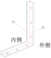
Example 1: as shown in the accompanying drawings 1-13, a door and window, including install framework 2 on wall body 1 and install well club 4 and the fan body 3 that can open and shut on framework 2, one side of fan body 3 with one side of framework 2 is articulated, framework 2 including fixing on wall body 1 attach frame 5 and be located attach the first connecting frame 6 of 5 indoor sides of frame and the second connecting frame 7 of outdoor side, attach frame 5 and be hollow structure, attach 5 inside packings of frame and have heat preservation 8, and heat preservation 8 is thermal-insulated insulation material, can effectively carry out the separation to indoor outer, reduces energy loss, the energy saving. In this embodiment, a door and a window are originally installed on a wall 1, an old frame body 9 is left on the wall 1 after the wall 1 is removed, the old frame body 9 does not need to be removed, and thus the wall 1 is not damaged by a complicated removing process, one side of the auxiliary frame 5 is an outdoor side, the other side is an indoor side, the outdoor side and the indoor side are shown in fig. 2-3, the first connecting frame 6 and the second connecting frame 7 are detachably connected, a first mounting plate 10 is arranged on one side of the first connecting frame 6 close to the auxiliary frame 5, a first locking tooth 11 is arranged on the first mounting plate 10, an L-shaped second mounting plate 12 is arranged at a position of the second connecting frame 7 corresponding to the first mounting plate 10, a second locking tooth 13 matched with the first locking tooth 11 is arranged on the second mounting plate 12, and a sealed cavity 14 is formed between the N-shaped second mounting plate 12 and the auxiliary frame 5, after the second connecting frame 7 is mounted on the auxiliary frame 5, a hole is drilled in the L-shaped second mounting plate 12, and the sealing cavity 14 is filled with a sealant. When dismantling the door and window again in the later stage, only dismantle old first connecting frame 6 and second connecting frame 7 can, inside attach frame 5 and remain, again with new first connecting frame 6 and second connecting frame 7 installation fix on attaching frame 5 can.
In this embodiment, the whole square of attaching frame 5, the U shaped steel that adopts wraps up old framework 9 completely, attaches frame 5 also can be semicircular in shape or semiellipse, and inside can set up the multicavity, does not confine the shape to, can be according to actual place and whole harmony confirm the cross-sectional shape that attaches frame 5.
As shown in fig. 2-3, the frame body 2 is provided with a frame main liner 15, the frame main liner 15 is provided on the second connection frame 7, which can enhance the strength of the whole frame body 2 and effectively support the frame body 2, in this embodiment, the frame main liner 15 is a square tube, and in this embodiment, a plurality of sides of the frame body 2 are connected by a connection piece 17, the connection piece 17 is provided at the inner side and the outer side of the corner of the frame body 2, the position of the connection piece 17 on the frame body 2 is shown in fig. 2, the connection piece 17 provided at the inner side of the frame body 2 is shown in fig. 12 and is installed at the position close to the outdoor side of the second connection frame 7, the connection piece 17 provided at the outer side of the frame body 2 is shown in fig. 13 and is installed in the sealed cavity 14 of the second connection frame 7, the connection piece 17 in the present invention is shown in fig. 12-13 and comprises a first connection plate 18 and at least one set of second connection plates 19, in this embodiment, the connection piece 17 for inner corner is shown in fig. 12, a set of second connecting plates 19 is provided, and as shown in fig. 13, the connecting pieces 17 for outer corners are provided with a set of second connecting plates 19, and the second connecting plates 19 may be provided in one set or in multiple sets, and the specific number is set according to actual conditions. The first connecting plate 18 is fixedly connected with a second connecting plate 19, the first connecting plate 18 is integrally arranged at a certain included angle, the second connecting plate 19 corresponds to the first connecting plate 18 in shape, the angle of the joint of the second connecting plate 19 and the first connecting plate 18 is the same everywhere, the first connecting plate 18 is used for connecting the adjacent sides of the frame body 2, the second connecting plate 19 is fixedly connected on the first connecting plate 18 and can be vertically arranged with the joint of the first connecting plate 18 or arranged at other fixed angles, so that the integral angle of the first connecting plate 18 is ensured to be constant, the integral angle of the first connecting plate 18 is equal to the angle of the side of the frame body 2, all the connecting angles in the embodiment are 90 degrees, therefore, the first connecting plate 18 is integrally arranged at 90 degrees, the corresponding second connecting plate 19 is also arranged at 90 degrees, and the joint of the second connecting plate 19 and the first connecting plate 18 is arranged at 90 degrees, if the angle between the sides of the frame 2 is other values, such as 75 degrees, the body of the first connecting plate 18 is at an angle matching the connection point of the sides of the frame 2. Use connecting piece 17 in this patent to connect the door and window, can guarantee the maximum strength of connection, make door and window's stability reach the highest, first connecting plate 18 and second connecting plate 19 all can not take place deformation, thereby make and be in stable state between the side all the time, guarantee can not influence the normal use that opens and shuts of door and window, thereby prolong door and window's life, and compare in prior art use cushion and bolt withhold the contained angle of frame, this patent only adds second connecting plate 19 and guarantees the angle stability of first connecting plate 18 on the basis of original side with first connecting plate 18 connection, moreover, the steam generator is simple in structure, and only install first connecting plate 18 on corresponding side during the installation can, need not to increase extra installation step, the time is saved, the efficiency is improved.
As shown in fig. 2, a drain hole is provided at the lower end of the connection between the frame body 2 and the fan body 3, the drain hole includes an upper drain hole provided on the connection surface between the frame body 2 and the fan body 3, a lower drain hole 20 provided outside the frame body 2, and a drain cavity 22 communicating the upper drain hole and the lower drain hole 20, a drain choke valve 21 is provided in the drain cavity 22, and one end of the drain choke valve 21 is fixedly connected to the upper drain hole.
As shown in fig. 7, the drainage choke valve 21 includes a fixing plate 23 connected to the upper drainage hole and a latex tube 24 located in the drainage cavity 22, the fixing plate 23 may be set to be in a shape of a strip, a circle, an ellipse or other shapes according to the shape of the upper drainage hole, the fixing plate 23 is provided with a through hole, and the latex tube 24 is fixedly disposed at one side of the through hole. One side of the through hole can be provided with a bulge, one end of the latex tube 24 is sleeved on the bulge, the latex tube 24 and the fixing plate 23 can be fixed in other modes, in the embodiment, the size of the fixing plate 23 is larger than that of the upper drainage hole, when the device is installed, the drainage and air-blocking valve 21 is assembled at first, the drainage and air-blocking valve 21 is installed on the upper drainage hole after the frame body 2 is installed, specifically, one end of the latex tube 24 far away from the fixing plate 23 penetrates through the upper drainage hole and is placed in the drainage cavity 22, the fixing plate 23 is positioned on the outer side of the upper drainage hole, the fixing plate 23 can be installed on the upper drainage hole through sealant or welding, so that rainwater can flow into the drainage cavity 22 through the drainage and then flow out through the lower drainage hole 20, otherwise, outdoor air is required to flow into the room through the drainage cavity 22 and then flow into the latex tube 24 through the lower drainage hole 20, and the airflow in the drainage cavity 22 is large, thus the latex tube 24 is closed, therefore, the air flow passing through the latex tube 24 is reduced, the convection of cold and hot air is greatly reduced, the energy loss in a house is greatly reduced, the energy is saved, outdoor dust cannot enter the frame body 2 or even enter an indoor windowsill along the drain hole, and the sealing performance of a window is improved.
As shown in fig. 3, a frame sub-liner 16 is provided on the side where the frame body 2 is hinged to the fan body 3, the frame sub-liner 16 fills the cavity of the frame body 2, and the frame sub-liner 16 is used for connecting the hinge, in this embodiment, one cavity is provided corresponding to the frame sub-liner 16, the frame sub-liner 16 filled in the cavity is a square tube in a square shape, and a plurality of corresponding cavities may be arranged side by side, and if the plurality of cavities are provided, the frame sub-liner 16 has an E shape as shown in fig. 10 or a U shape as shown in fig. 11, and if the cavities have other shapes, the frame sub-liner 16 has other shapes to be attached to the inner wall of the cavity, and when the hinge is connected to the frame body 2, as shown in fig. 3, the dovetail screw penetrates through the frame sub-liner 16 from the second connection frame 7 near the indoor side to the frame main liner 15, the frame sub-liner 16 is attached to the screw so that the connection of the screw and the frame body, the one end that hinge and framework 2 are connected can not take place to become flexible, compares in prior art through increasing the cushion to support fan body 3 in the below of framework 2 and fan body 3 junction, can fundamentally solve fan body 3 and warp and move down the problem, effectively improves door and window's life.
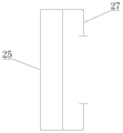
As shown in fig. 4-5, in this embodiment, a main fan liner 25 is disposed on the fan body 3, so as to enhance the strength of the whole fan body 3 and effectively support the fan body 3, the main fan liner 25 is in a bridge shape, the main fan liner 25 is circumferentially attached to the fan body 3, and at least one set of support legs 27 is disposed inside the main fan liner 25. In this embodiment, the inner chamber setting of fan owner lining 25 laminating fan body 3, the fan body 3 outside is provided with recess 26, recess 26 is used for installing five metals or sealing device, corresponding inner chamber and recess 26 correspond the department inwards sunken, divide into two concatenation settings with fan owner lining 25 along the depressed part among the prior art, can reduce whole fan body 3's intensity like this, in this embodiment, fan owner lining 25 is bridge type and integrative setting, the inner wall setting of whole laminating inner chamber, and be provided with corresponding landing leg 27 in the depressed part and increase whole support intensity, in this embodiment, landing leg 27 is provided with two sets ofly, every group sets up relatively, the centre is used for corresponding laying the depressed part, also can set up fan owner lining 25 into the bridge type as shown in fig. 9, landing leg 27 is provided with a set of. In this embodiment, a plurality of sides of the fan body 3 are connected by the connecting member 17, the connecting member 17 is disposed at the inner side and the outer side of the corner of the fan body 3, the position of the connecting member 17 on the fan body 3 is as shown in fig. 4-5, the connecting member 17 disposed at the inner side of the fan body 3 is installed at a position close to the outdoor side, the connecting member 17 disposed at the outer side of the frame body 2 is installed at the groove 26, and is all fixedly connected with the fan main liner 25, so as to increase the overall strength, the sides of the fan body 3 are all connected by the connecting member 17, the difference between the connecting member 17 and the connecting member 17 at the frame body 2 is only the size of the whole connecting member 17 and the number of the second connecting plates 19, and these needs are set according to actual conditions.
In the embodiment, as shown in fig. 1, a handle is required to be installed at one end of the fan body, which is attached to the mullion 4, the handle is fixed to the fan body side by two bolts, a fan secondary lining 28 is arranged at the handle installation position of the fan body, the fan secondary lining 28 fills the cavity of the handle installation, one cavity is arranged corresponding to the frame secondary lining 16 shown in fig. 4, the fan secondary lining 28 filled in the cavity is a square pipe in a square shape, and the corresponding cavity can be a plurality of cavities side by side, if the cavity is a plurality of cavities, the shape of the frame secondary lining 16 is E-shaped as shown in fig. 10 or U-shaped as shown in fig. 11, if the cavity is other shapes, the fan secondary lining 28 is other shapes attached to the inner wall of the cavity, when the handle screw is connected to the fan body 3, as shown in fig. 4, the screw penetrates through the fan secondary lining 28 from the indoor side of the fan body 3 until the fan secondary lining 28 is attached to the screw, so that the connection between, the stability of screw reinforcing, the one end that handle and fan body 3 are connected can not take place to become flexible, effectively improves door and window's life.
As shown in fig. 6, a mullion main lining 33 is arranged on the mullion 4, so that the strength of the whole mullion 4 can be enhanced and the mullion 4 can be effectively supported, in this embodiment, the mullion main lining 33 is a square tube, a locking point 29 is arranged on one side of the mullion 4 connected with the fan body 3, the locking point 29 is arranged in cooperation with the handle 30, the locking point 29 is arranged on one side of the mullion main lining 33, as shown in fig. 8, a connecting portion 31 is arranged on one side of the locking point 29 close to the mullion main lining 33, and the connecting portion 31 is fixedly connected with the mullion main lining 33 through a bolt. The connection screw between the locking point 29 and the mullion 4 is shown in fig. 6, the connecting portion 31 covers the outer side of the mullion main lining 33, and the locking point 29 is connected and fixed from the connecting portion 31 to the mullion 4 by a screw, so that the screw can be locked on the mullion main lining 33, and compared with the installation on a cavity, the screw has higher stability, thereby making the locking point 29 more durable.
The mullion 4 is provided with a mullion auxiliary lining 34 near the indoor side, the mullion auxiliary lining 34 is provided with one or two or more than two, and if the window is too large, hinges need to be fixed on the mullion 4.
As shown in fig. 6, the joints of the mullion 4 are also connected by the connecting pieces 17, and the difference between the connecting pieces 17 and the frame 2 is only the size of the whole connecting pieces 17 and the number of the second connecting plates 19, which need to be set according to actual conditions.
As shown in fig. 2, 3 and 6, the joints of the fan body 3 and the frame body 2 and the mullion 4 are sealed by a plurality of sealing strips 32, in this embodiment, two sealing strips 32 are provided, or three or four sealing strips can be adopted, and the sealing strips 32 are seamless adhesive tapes and have the same overall height, so that the overall sealing effect is improved.
Example 2: as shown in fig. 14, the auxiliary frame 5 is installed in a closed manner for constructing a new house in this embodiment. The auxiliary frame 5 is integrally installed on the outer side of the wall body 1. When the later stage is changed, only old first connecting frame 6 and second connecting frame 7 need be dismantled, and inside attaches frame 5 and remains, again with new first connecting frame 6 and second connecting frame 7 installation fix on attaching frame 5 can.
Other parts in this embodiment are the same as those in embodiment 1, and are not described in detail.
Example 3: as shown in fig. 15, the auxiliary frame 5 is closed in the present embodiment for building a new house. A part of the auxiliary frame 5 is arranged on the inner side of the wall body 1, so that the stability of the auxiliary frame 5 can be effectively improved.
Other parts in this embodiment are the same as those in embodiment 1, and are not described in detail.
Example 4: as shown in fig. 16 to 18, a method of installing a door and window, S1, as shown in fig. 16, includes fixing an auxiliary frame 5 to a wall 1 or an old frame 9 by expansion bolts, and installing a new project: fixing the finished auxiliary frame 5 at a planned opening for installation, fixing the outer arm in the wall body 1 by using a steel nail, and filling the opening and the auxiliary frame 5 by using expansion glue to be cemented; old engineering reconstruction: welding the cut U-shaped lining on the matched hole, matching with the old frame body 9, coating the old frame body 9, fixing the old frame body 9 on the wall body 1 through bolts, performing waterproof and heat-preservation treatment on the surface of the auxiliary frame 5, and waiting for installing the frame body 2; s2, as shown in fig. 17-18, the inner sides between the adjacent second connection frames 7 are fixed by the connection piece 17 in fig. 12, the outer sides are connected and fixed by the connection piece 17 in fig. 13, the second connection frames 7 are installed on the outdoor side of the auxiliary frame 5 by the sealant, the sealant is filled in the sealed cavity 14, the first connection frame 6 coated with the sealant is installed on the indoor side of the auxiliary frame 5 and fixed with the second connection frame 7, and the first connection frame 6, the second connection frame 7 and the auxiliary frame 5 are fixedly connected by the expansion bolt; s3, fixedly connecting the inner side and the outer side of fan body 3 through connecting piece 17, and installing mullion 4 on frame body 2 through connecting piece 17; s4, installing drain choke valve 21 at the drain hole, installing lock point 29 at the corresponding position of mullion 4 and fan body 3, installing hinge at the corresponding position of fan body 3, and installing the other end of hinge on fan body 3; s5, handle 30 is mounted at the position of fan body 3 corresponding to lock point 29.
It will be evident to those skilled in the art that the invention is not limited to the details of the foregoing illustrative embodiments, and that the present invention may be embodied in other specific forms without departing from the spirit or essential attributes thereof. The present embodiments are therefore to be considered in all respects as illustrative and not restrictive, the scope of the invention being indicated by the appended claims rather than by the foregoing description, and all changes which come within the meaning and range of equivalency of the claims are therefore intended to be embraced therein. Any reference sign in a claim should not be construed as limiting the claim concerned.
Furthermore, it should be understood that although the present description refers to embodiments, not every embodiment may contain only a single embodiment, and such description is for clarity only, and those skilled in the art should integrate the description, and the embodiments may be combined as appropriate to form other embodiments understood by those skilled in the art.