Garbage pyrolysis tar separation device
Technical Field
The invention belongs to the technical field of petrochemical and household garbage treatment equipment, and particularly relates to a garbage pyrolysis tar separation device.
Background
At present, domestic market tar separation mainly adopts and sprays and combine centrifugal separation, the biggest shortcoming of spraying separation is limited by the temperature height of coolant, the vapor of coolant evaporation is difficult to in time spill simultaneously, when the coolant temperature rose, the entrapment efficiency of tar reduces along with it, tar passes through the drain pipe on next step and gets into the tank, just can cyclic utilization after carrying out water treatment again, consequently current tar separation technology and equipment structure are complicated, need recirculated water cooling, centrifugal separation, still need the great tank of area, still need often to wash tank bottom tar, increase the complexity of technology clearance operation, the acquisition cost of equipment cost. The separation of tar and water is the mature equipment commonly existing in the fields of petrochemical industry and domestic garbage treatment at present, most of domestic processes adopt a water washing method to remove tar, and the combined application of a water washing tower and a Venturi device is used for removing heavy substance tar in gaseous components, so that the tar removing and separating efficiency is improved, but a large amount of water resources are needed, secondary pollution or treatment is caused, and the treatment cost is high. Most tar separation equipment generally has the defects of complex equipment structure, high manufacturing cost, high cleaning and maintenance cost and is not beneficial to the continuous and stable operation of an engineering device in terms of economy and time. In addition, under the condition of higher temperature, tar is mainly in the form of black viscous liquid with relative density more than 1, and the asphalt content is maximum, so that the fuel gas entering the generator set must be purified.
Therefore, there is a need to solve the above-mentioned disadvantages in the prior art.
Disclosure of Invention
The invention mainly aims to provide a garbage pyrolysis tar separation device which is detachably mounted and has a prolonged service life.
The technical scheme adopted by the invention is as follows:
the utility model provides a rubbish pyrolysis tar separator, includes mechanism, pyrolysis oil gas rapid cooling trap and tar separating tank admits air, wherein admit air the mechanism and link to each other with pyrolysis oil gas rapid cooling trap, tar separating tank in proper order, admit air mechanism and pyrolysis oil gas rapid cooling trap all are located the top of tar separating tank. The pipe orifice of the garbage pyrolysis tar separation device is also connected with a centrifugal pump.
The garbage pyrolysis tar separation device is also connected with a cooler, and the cooler is connected with a centrifugal pump.
The air inlet mechanism consists of a push rod motor, a one-way swing type air inlet piston and a T-shaped three-way pipe. The top port of the T-shaped three-way pipe is provided with a push rod motor, the lower port of the T-shaped three-way pipe is provided with a one-way swing type air inlet piston, and the left port of the T-shaped three-way pipe is a high-temperature pyrolysis oil gas inlet.
An air inlet hole is formed in the unidirectional swing type air inlet piston, so that pyrolysis oil gas or a small amount of water vapor can enter equipment below the piston. The lower part of the unidirectional swing type air inlet piston is provided with a turnover cover with a spring to prevent the reverse channeling of the air below.
Two purified gas outlets are formed in the outer side of the top of the pyrolysis oil gas quenching catcher, so that the cooling efficiency is influenced by timely dispersion of vapor of a cooling medium and the cooled and purified pyrolysis gas. The top of the wallboard of the pyrolysis oil gas quenching catcher is provided with a water spray nozzle, and tar in pyrolysis oil gas is cooled and caught by spraying cooling water or oil water. The inner side of the side wall of the pyrolysis oil gas quenching catcher is provided with a first overflow clapboard groove. The side wall of the pyrolysis oil gas quenching catcher is also connected with a bypass pipeline, and the bypass pipeline is introduced into the tar separation tank. The oil-water mixture gradually accumulated in the pyrolysis oil-gas quenching catcher flows across the first overflow partition plate groove and flows into the lower tar separation groove through the bypass pipeline.
A ball valve is arranged in the bypass pipeline. In the initial stage of operation, the ball valve is kept closed to prevent pyrolysis oil gas from directly entering the lower tar separation tank. Heavy oil enters the tar separation tank through a lower pipe orifice of the pyrolysis oil gas quenching catcher.
The lower part of the pyrolysis oil gas quenching catcher is provided with an oil guide water pipe.
The tar separation tank comprises three inner cavities: cavity one, cavity two and cavity three. The first chamber emphasizes the rough separation of oil and water, most of heavy oil, and is discharged from the first chamber. And the second cavity emphasizes the separation of light oil. The third cavity is mainly used for fine separation of light oil.
The bottom of the first cavity is provided with a first heavy oil outlet, and the upper part of the first cavity is provided with a first clear oil outlet. The bottom of the second cavity is provided with a second heavy oil outlet, and the upper part of the second cavity is provided with a second clear oil outlet. The bottom of the cavity III is provided with a heavy oil outlet III, and the upper part of the cavity III is provided with a clear oil outlet III.
The oil guide water pipe is arranged in the first cavity. The lower end of the oil guide water pipe is connected with an overflow basket cover. The inside water hammer-proof check valve that is provided with of overflow basket cover.
The first cavity and the second cavity are separated by a steel plate with an overflow square through hole. A first flow baffle plate 18b welded on the wall plate of the tar separation tank is arranged in front of the overflow square through hole between the first cavity and the second cavity, and a second flow baffle plate 18a welded on the wall plate of the tar separation tank is arranged in front of the overflow square through hole between the second cavity and the third cavity. The oil-water mixing short circuit between the three cavities is prevented by pressure drop resistance.
The first cavity is welded with No. two overflow partition plate grooves on the inner wall close to one side of the second cavity, the second cavity is welded with No. three overflow partition plate grooves on the inner wall close to one side of the third cavity, and the third cavity is welded with No. four overflow partition plate grooves on the inner wall close to one side of the second cavity. The bottom plate of all overflow baffle grooves is the wallboard of slope, makes things convenient for the light oil to flow out.
No. two overflow baffle grooves and chamber one, chamber two separate to be equipped with the mouth that sweeps between the steel sheet, No. three overflow baffle grooves and chamber two, chamber three separate to be equipped with No. two and sweep the mouth between the steel sheet, No. four overflow baffle grooves and chamber two, chamber three separate to be equipped with No. three and sweep the mouth between the steel sheet. The purging port can be filled with nitrogen or water. When nitrogen is introduced, light floating oil can be blown and discharged, and when water is introduced, the wall plate can be washed to prevent oil stains from accumulating and blocking.
A first water replenishing opening is formed in the upper portion of the top wall of the first cavity, and a first flow guide cover is connected to the lower portion of the first water replenishing opening. And the upper part of the top wall of the cavity III is provided with a second water replenishing port, and the lower part of the second water replenishing port is connected with a second air guide sleeve.
The tar separation tank is also provided with a liquid level meter and a thermometer. The liquid level meter is positioned outside the equipment at the third side of the cavity and the right side of the cavity. The thermometer is positioned on the outer side of the cavity three equipment close to the pipe orifice. The liquid level meter is used for controlling the water supplement amount and the overflow condition of the light oil-water mixture or floating oil crossing the partition plate by observing the liquid level in the tank through on-site direct reading or remote transmission. The thermometer is used for reading the temperature of the solution in the tar separation tank and starting the cooler in real time to cool the cooling water or the oil-water mixed liquid pumped back to the pyrolysis oil-gas trap, and under the general condition, the cooler is not frequently started.
The invention has the following remarkable effects:
the invention firstly adopts the self-designed non-return air inlet mechanism, ensures the safety of preventing the fuel gas from leaking into the device system, then the tar substance in the fuel gas is quenched and trapped by the circulating water and passes through the equipment quenching trap, the overflow basket cover and the tar separating tank device, realizes the multi-stage purification, purification and precipitation process of the tar, and simultaneously, combines the centrifugal pump and the existing cooler of the process to cool the water, realizes the recycling of cooling water, reduces the utilization amount of water resources, thereby realizing the recycling of the water resources and saving the water resources. Oil-water mixture in three cavities of the tar separation tank is kept stand for separation, so that multi-stage separation of light tar and heavy tar is realized, the gas entering the quenching catcher equipment is quenched and caught by combining circulating cooling water of a centrifugal pump and a quencher, and the effectiveness of cooling and trapping tar is improved. Light oil is sent out from the clapboard groove of the device, heavy tar is sent out from the outlet of the lower pipe, the generated tar enters the next process stage for treatment and the circulation of cooling water, and the continuous and stable operation of the device is ensured. In addition, the device has simple structure, the pyrolysis oil gas quenching catcher and the tar separation tank can be manufactured only by welding the correspondingly designed steel plates, and the manufacturing cost and the cost are low. The tar automatically flows out through the clapboard groove and the lower pipe orifice, and the manual cleaning and maintenance cost is reduced.
Drawings
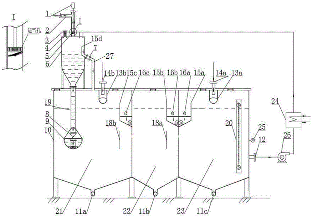
FIG. 1 is a front view of a refuse pyrolysis tar separation apparatus;
FIG. 2 is a top view of a refuse pyrolysis tar separation apparatus;
FIG. 3 is a left side view of the garbage pyrolytic tar separation device.
Wherein: 1 is a push rod motor; 2 is a T-shaped three-way pipe; 3 is a purified gas outlet; 4 is a water spraying nozzle; 5 is a one-way swing type air inlet piston; 6 is a pyrolysis oil gas quenching catcher; 7 is a ball valve; 8 is a water hammer-proof check valve; 9 is an overflow basket cover; 10 is a tar separation tank; 11a is a first heavy oil outlet; 11b is a second heavy oil outlet; 11c is a No. three heavy oil outlet; 12 is a pipe orifice; 13a is a second air guide sleeve; 13b is a first dome; 14a is a second water replenishing port; 14b is a first water replenishing port; 15a is a No. four overflow clapboard groove; 15b is a No. three overflow clapboard groove; 15c is a second overflow clapboard groove; 15d is a first overflow clapboard groove; 16a is a No. three purging port; 16b is a second purge port; 16c is a first purge port; 17a is a No. three clear oil outlet; 17b is a No. two clear oil outlet; 17c is a clear oil outlet I; 18a is a second flow baffle; 18b is a first flow baffle; 19 is an oil guide water pipe; 20 is a liquid level meter; 21 is a cavity I; 22 is a cavity II; 23 is a cavity III; 24 is a cooler; 25 is a thermometer; 26 is a circulating pump; and 27 is a bypass pipeline.
Detailed Description
The invention is described in detail below with reference to the figures and specific embodiments.
As shown in fig. 1-3, the invention provides a garbage pyrolysis tar separation device, which comprises an air inlet mechanism, a pyrolysis oil gas quenching catcher 6 and a tar separation tank 10, wherein the air inlet mechanism is sequentially connected with the pyrolysis oil gas quenching catcher 6 and the tar separation tank 10, and the air inlet mechanism and the pyrolysis oil gas quenching catcher 6 are both positioned at the top of the tar separation tank 10. The pipe orifice 12 of the garbage pyrolysis tar separation device is also connected with a centrifugal pump 26 and is used for recycling cooling circulating water and reducing the using amount of water during actual work.
The garbage pyrolysis tar separation device is also connected with a cooler 24, and the cooler 24 is connected with a centrifugal pump 26.
The air inlet mechanism consists of a push rod motor 1, a one-way swing type air inlet piston 5 and a T-shaped three-way pipe 2. The top port of the T-shaped three-way pipe 2 is provided with a push rod motor 1, the lower port of the T-shaped three-way pipe 2 is provided with a one-way swing type air inlet piston 5, and the left port of the T-shaped three-way pipe 2 is a high-temperature pyrolysis oil gas inlet.
An air inlet hole is formed in the unidirectional swing type air inlet piston 5, so that pyrolysis oil gas or a small amount of water vapor can enter equipment below the piston. The lower part of the one-way swing type air inlet piston 5 is provided with a flip cover with a spring to prevent the reverse channeling of the air below. The one-way swing type air inlet piston 5 has the main function of sealing air, and simultaneously removing oil stains through up-and-down movement when pyrolytic oil stains are attached to the inner wall of the T-shaped three-way pipe 2, so that blockage is prevented, and ventilation is not smooth.
Two purified gas outlets 3 are arranged on the outer side of the top of the pyrolysis oil gas quenching catcher 6, so that the cooling efficiency is influenced by timely dispersion of vapor of a cooling medium and the cooled and purified pyrolysis gas. The top of the wallboard of the pyrolysis oil gas quenching catcher 6 is provided with a water spray nozzle 4, and tar in pyrolysis oil gas is cooled and caught by spraying cooling water or oil water. The inner side of the side wall of the pyrolysis oil gas quenching catcher 6 is provided with a first overflow clapboard groove 15 d. The side wall of the pyrolysis oil gas quenching catcher 6 is also connected with a bypass pipeline 27, and the bypass pipeline 27 is introduced into the tar separation tank 10. The oil-water mixture gradually accumulated in the pyrolysis oil-gas quenching catcher 6 flows into the lower tar separation tank 10 through the bypass pipeline 27 after passing through the first overflow partition groove 15 d.
A ball valve 7 is arranged in the bypass pipe 27. In the initial stage of operation, the ball valve 7 is kept closed to prevent pyrolysis oil gas from directly entering the lower tar separation tank 10. Heavy oil enters the tar separation tank 10 through a pipe orifice at the lower part of the pyrolysis oil gas quenching catcher 6.
The lower part of the pyrolysis oil gas quenching catcher 6 is provided with an oil guide water pipe 19.
The tar separation tank 10 includes three inner chambers: cavity one 21, cavity two 22 and cavity three 23. And the first cavity 21 and the second cavity 22, and the second cavity 22 and the third cavity 23 are separated by steel plates with overflow square through holes. Chamber one 21 emphasizes the coarse separation of oil and water, most of the heavy oil, and is discharged from this chamber. The second cavity 22 emphasizes the separation of light oil. The main function of chamber three 23 is the fine separation of the light oil.
The first heavy oil outlet 11a is arranged at the bottom of the first cavity 21, and the first clear oil outlet 17c is arranged at the upper part of the first cavity. The bottom of the second cavity 22 is provided with a second heavy oil outlet 11b, and the upper part is provided with a second clear oil outlet 17 b. The bottom of the cavity III 23 is provided with a third heavy oil outlet 11c, and the upper part is provided with a third clear oil outlet 17 a. Heavy oil is discharged from a heavy oil outlet, light oil is discharged from a light oil outlet, and the light oil enters the next process and is treated or collected and utilized in the whole system.
The oil and water guide pipe 19 is arranged in the first cavity 21. The lower end of the oil guide water pipe 19 is connected with an overflow basket cover 9. The overflow basket cover 9 is internally provided with a water hammer-proof check valve 8 for preventing the backflow of cavity oil and water and reducing the impact of the oil and water on the inner wall of the cavity in an overflow mode.
And the first cavity 21 and the second cavity 22, and the second cavity 22 and the third cavity 23 are separated by steel plates with overflow square through holes. A first flow baffle plate 18b welded on the wall plate of the tar separation tank 10 is arranged in front of the overflow square through hole between the first cavity 21 and the second cavity 22, and a second flow baffle plate 18a welded on the wall plate of the tar separation tank 10 is arranged in front of the overflow square through hole between the second cavity 22 and the third cavity 23. The oil-water mixing short circuit between the three cavities is prevented by pressure drop resistance.
No. two overflow partition plate grooves 15c are welded on the inner wall of the first cavity 21 close to one side of the second cavity 22, No. three overflow partition plate grooves 15b are welded on the inner wall of the second cavity 22 close to one side of the third cavity 23, and No. four overflow partition plate grooves 15a are welded on the inner wall of the third cavity 23 close to one side of the second cavity 22. When the light oil on the liquid surface floats upwards and accumulates, the water supplement amount is increased to enable the light oil to overflow to the partition plate cavity of the overflow partition plate groove. The bottom plates of the overflow baffle grooves 15a, 15b and 15c are inclined wall plates, so that light oil can flow out conveniently.
A first purging opening 16c is formed between the second overflow partition plate groove 15c and the partition steel plates of the first cavity 21 and the second cavity 22, a second purging opening 16b is formed between the third overflow partition plate groove 15b and the partition steel plates of the second cavity 22 and the third cavity 23, and a third purging opening 16a is formed between the fourth overflow partition plate groove 15a and the partition steel plates of the second cavity 22 and the third cavity 23. The purging port can be filled with nitrogen or water. When nitrogen is introduced, light floating oil can be blown and discharged, and when water is introduced, the wall plate can be washed to prevent oil stains from accumulating and blocking.
The upper part of the top wall of the first cavity 21 is provided with a first water replenishing port 14b, and the lower part of the first water replenishing port 14b is connected with a first air guide sleeve 13 b. And a second water replenishing port 14a is arranged at the upper part of the top wall of the cavity III 23, and a second air guide sleeve 13a is connected to the lower part of the second water replenishing port 14 a.
The tar separation tank 10 is also provided with a liquid level meter 20 and a thermometer 25. The gauge 20 is located outside the right side of the device in chamber three 23. A thermometer 25 is located outside the chamber three 23 device near the nozzle 12. The liquid level meter 20 is used for controlling the water supplement amount and the overflow condition of the light oil-water mixture or floating oil crossing the partition plate by observing the liquid level in the tank through on-site direct reading or remote transmission. The thermometer 25 is used for reading the temperature of the solution in the tar separation tank 10 and starting the cooler 24 in real time to cool the cooling water or the oil-water mixed liquid pumped back to the pyrolysis oil-gas trap, and the cooler is not frequently started under the general condition.
The use steps of the garbage pyrolysis tar separation device provided by the invention are as follows:
water is firstly added into the tar separation tank 10 through the second water replenishing port 14a and the first water replenishing port 14b, and the second air guide sleeve 13a and the first air guide sleeve 13b prevent the water from impacting the bottom plate of the tar separation tank 10. The amount of the added water is observed or controlled by a liquid level meter 20, and the water is stopped when the liquid level in the tank is added to a position 100mm away from the top of the No. four overflow clapboard tank plate 15 a. And closing the ball valve 7, starting the circulating pump 26 to add water into the pyrolysis oil gas quenching catcher 6, and communicating the water in the tar separation tank 10 and the water in the pyrolysis oil gas quenching catcher 6. When the water in the pyrolysis oil gas quenching catcher 6 is stabilized to a certain liquid level, the treated high-temperature pyrolysis oil gas is introduced into the gas inlet mechanism for formal separation. The unidirectional swing type piston 5 is kept at the upper top position at the beginning of operation, during operation, when oil stains on the inner wall of the T-shaped three-way pipe 2 are removed or other equipment is overhauled for short pause, the unidirectional swing type piston 5 can be positioned below the air inlet to seal the lower air, high-temperature pyrolysis oil gas is quenched by cooling water of the water spray nozzle 4 to collect tar components, and heavy oil flows into the cavity I21 in the lower tar separation tank 10 from the lower equipment port. The pyrolysis gas and the water vapor which are primarily purified and cooled at the upper part of the pyrolysis oil gas quenching catcher 6 enter the next process system from the purified gas outlet 3 for treatment. When a certain amount of oil-water mixture and light oil are accumulated on the liquid surface in the trap, the ball valve 7 can be opened to flow into the first cavity 21 of the lower tar separation tank 10.
The oil water containing heavy oil components enters the first cavity 21 through the oil water guide pipe 19, the water hammer prevention check valve 8 and the overflow basket cover 9, and the three elements are combined to prevent the oil water from impacting the bottom plate of the oil water focusing and separating tank 10 and turbulent disturbance of mixed oil water in the first cavity 21 from influencing the separation effect and time of heavy oil. The first cavity 21 mainly functions to primarily separate oil-water mixture, oil-water with higher concentration enters the second cavity 22 through the opening to be separated again, and water with higher basic cleanliness and a few parts of oil in the third cavity 23 are sequentially separated.
When a certain amount of oil-water mixture or light oil is accumulated on the liquid level, the oil-water mixture or the light oil can flow into the overflow partition plate groove 15a/b/c by adjusting the water supplement amount, and the bottom plate of the overflow partition plate groove is inclined to facilitate the outflow of the light oil and flows out through the light oil outlet 17 a/b/c; the purging ports 16a/b/c are filled with nitrogen or clean water, so that oil dirt and dirt in the partition plate groove can be purged or removed.
In addition, the temperature of the water with higher purity or the oil-water solution with smaller oil content in the third cavity 23 can be slowly increased due to long-time operation, and the temperature of the solution in the cavity can be observed through the thermometer 25. At this time, the cooling water pumped back to the pyrolysis oil gas quenching catcher 6 can be cooled by turning on the cooler 24, so that the efficiency of trapping the pyrolysis oil gas therein is prevented from being reduced.