Disclosure of Invention
Aiming at the situation and overcoming the defects of the prior art, the invention provides the cardiovascular patient rehabilitation training device, which effectively achieves the aim of training the walking of the patient, increases the function of training the climbing capability of the patient, improves the stability of the device, optimizes the function of adjusting the left-right distance of the device according to the patient, achieves the aim of training the knee joint of the patient, adds the function of enabling the patient to walk up and down slopes, solves the problem of inconvenient movement of the device, achieves the function of adjusting the climbing height, and avoids the risk of the patient being injured by clamping.
In order to achieve the purpose, the invention adopts the following technical scheme: comprises a bottom plate, a first sliding mechanism is connected with the left side in the bottom plate in a sliding manner, a first travelling mechanism is arranged above the first sliding mechanism, a second sliding mechanism is connected with the right side in the bottom plate in a sliding manner, a second travelling mechanism is arranged above the second sliding mechanism, a supporting mechanism is arranged at the front end of the bottom plate, a first linkage mechanism is connected with the left side in the supporting mechanism in a sliding manner, the lower end of the first linkage mechanism is connected with the first travelling mechanism in a sliding manner, a second linkage mechanism is connected with the right side in the supporting mechanism in a sliding manner, the lower end of the second linkage mechanism is connected with the second travelling mechanism in a sliding manner, the bottom plate, the supporting mechanism, the first linkage mechanism and the second linkage mechanism are mutually matched to form a limiting structure with the height of the first travelling mechanism and the height of the second travelling mechanism, and a first hand wheel is rotatably connected with the front end of the bottom plate, the lower end of the first hand wheel is meshed with a driving transmission rod, the first hand wheel and the driving transmission rod are matched with the first sliding mechanism and the second sliding mechanism to form a limiting structure of the angle between the first traveling mechanism and the second traveling mechanism, and the middle part of the bottom plate is rotatably connected with the first traveling mechanism and the second traveling mechanism
Preferably, first running gear is including a tripod, and two slots have been seted up to the right side lower extreme of tripod, both ends rotate respectively around the tripod and are connected with a driven cylinder, the lower extreme of tripod rotates and is connected with a initiative cylinder, and a drive gear of the right side fixedly connected with of initiative cylinder, the common cover is equipped with same walking area between the outside of initiative cylinder and every driven cylinder, the inside a plurality of location lugs that is equipped with in right side of tripod, the inside sliding connection in right side of tripod has a location inserted block, and the right side of location inserted block is rotated and is connected with a locking connecting rod, second running gear and first running gear structural similarity and bilateral symmetry set up.
Preferably, first slide mechanism is equipped with one including a carriage and can follow the gliding upset slider around the carriage in the carriage, and both ends all rotate around the upset slider and are connected with an upset vaulting pole, and the corresponding ditch inslot all can be arranged in to the upper end of every upset vaulting pole, every the equal fixedly connected with first extension spring in middle part of upset vaulting pole, every the other end of first extension spring all with upset slider fixed connection, the front end of carriage rotates and is connected with a drive bevel gear, and drive bevel gear's rear end meshing has an adjusting screw, adjusting screw run through the middle part of upset slider and with upset slip screw-thread fit, drive bevel gear can follow the horizontal slip of drive transfer line and rotate with drive dwang synchronous, second slide mechanism is the same with first slide mechanism structure and bilateral symmetry sets up.
Preferably, first link gear is including a gangbar, and the rear end screw-thread fit of gangbar has a connection knob, and the connection knob can with the locking connecting rod sliding connection who corresponds, the lower extreme left side tip of gangbar runs through corresponding tripod and can follow the tripod that corresponds and slide around, the outside slip cover of gangbar is equipped with a spacing rectangular block, second link gear is the same with first link gear structure and bilateral symmetry sets up.
Preferably, the supporting mechanism comprises a supporting main body, a plurality of circular chutes are formed in the supporting main body, each limiting rectangular block is arranged in the corresponding circular chute and can slide left and right along the corresponding circular chute, the middle part of the supporting main body is rotatably connected with two crawling transmission rods, a crawling gear capable of rotating synchronously with the crawling transmission rods is slidably sleeved on the outer side of each crawling transmission rod, a first rack fixedly connected with a first linkage mechanism is meshed with the rear side of the crawling gear on the left side, a second rack fixedly connected with a second linkage mechanism is meshed with the front side of the crawling gear on the right side, a positioning rod is rotatably connected to the middle part of the upper end of the supporting main body, an operating rod is rotatably connected to the rear end of the positioning rod, a positioning groove is formed in the middle part of the supporting main body, and the operating rod and the positioning groove are matched with each other to form a positioning rod limiting structure, the lower extreme of locating lever rotates and is connected with an L shape connecting rod, and the lower extreme of L shape connecting rod rotates and is connected with a clutch gear, and clutch gear can mesh with every transfer line of crawling, the lower extreme that supports the main part rotates with spacing slider to be connected, the rear end that supports the main part rotates and is connected with a U-shaped frame, and the left and right sides of U-shaped frame all rotates and is connected with a support vaulting pole, the rear end that supports the main part is equipped with a plurality of ratchets, and every support vaulting pole is mutually supported with the limit structure who corresponds the ratchet and is formed the U-shaped frame, the rear side rotation that supports the main part is connected with a bedplate, the equal fixedly connected with incomplete ratchet of the left and right sides of bedplate, support the main part about, support the incomplete ratchet of equal fixedly connected with
Preferably, a first bidirectional screw rod is rotatably connected to the bottom plate, two adjusting slide blocks are sleeved on the outer side of the first bidirectional screw rod in a threaded manner, the lower end of each adjusting slide block is rotatably connected with a plurality of adjusting connecting rods, each adjusting connecting rod is rotatably connected with a corresponding sliding frame, each adjusting connecting rod, each adjusting slide block and the first bidirectional screw rod are mutually matched to form a limiting structure of a first sliding mechanism and a second sliding mechanism, a control driven rod is meshed at the front end of the first bidirectional screw rod, the upper end of the control driven rod is rotatably connected with a first universal block, the upper end of the first universal block is rotatably connected with a sliding rod, the upper end of the sliding rod is slidably connected with a hollow rod, the upper end of the hollow rod is rotatably connected with a second universal block, the upper end of the second universal block is rotatably connected with a control driving rod, and the control driving rod is rotatably connected with the support main body, the upper end of the control driving rod is meshed with a second bidirectional screw rod, the left side and the right side of the second bidirectional screw rod are respectively in threaded fit with the corresponding limiting rectangular blocks, a second hand wheel is arranged at the right end of the second bidirectional screw rod, and the second hand wheel and the second bidirectional screw rod are mutually matched to form a limiting structure of the first linkage mechanism and the second linkage mechanism.
Preferably, the bottom plate is rotatably connected with a driving gear, the lower end of the middle part of the driving gear is meshed with a worm, and the rear end of the worm is fixedly connected with a motor.
Compared with the prior art, the invention has the following beneficial effects: 1. this device has first running gear and second running gear, and patient's left and right feet can be placed respectively to first running gear and second running gear, and the effectual purpose that has reached the walking of taking exercise patient. 2. The device is provided with a supporting mechanism, a first linkage mechanism and a second linkage mechanism, the first linkage mechanism can be connected with the first travelling mechanism, the second linkage mechanism can be connected with the second travelling mechanism, and the function of training the climbing ability of a patient is effectively increased. 3. The device is provided with the bottom plate, the U-shaped frame and the supporting stay bar, so that the stability of the device is effectively improved. 4. The device is provided with a first bidirectional screw rod, a hollow rod, a sliding rod, a second bidirectional screw rod, an adjusting slide block and an adjusting connecting rod, and the function of adjusting the left and right distance of the device according to a patient is effectively optimized. 5. The device is provided with the reversible seat plate, and the aim of training the knee joint of the patient is effectively fulfilled. 6. The device is provided with a first sliding mechanism, a second sliding mechanism, a first hand wheel and a driving sliding rod, wherein the first sliding mechanism, the second sliding mechanism, the first hand wheel and the driving sliding rod are matched to enable the first walking mechanism and the second walking mechanism to be inclined synchronously, and the function of enabling a patient to walk up and down slopes is effectively added. 7. The device is provided with the base and the roller tangent to the ground, so that the problem of inconvenient movement of the device is effectively solved. 8. This device has the transfer line of crawling, crawls gear and clutch gear, and the effectual height-adjustable's of climbing function that has reached. 9. The left side of the first sliding mechanism and the right side of the second sliding mechanism of the device are respectively provided with the isolation plate, so that the risk that a patient is injured by clamping is effectively avoided.
Drawings
The accompanying drawings, which are included to provide a further understanding of the invention and are incorporated in and constitute a part of this specification, illustrate embodiments of the invention and together with the description serve to explain the principles of the invention and not to limit the invention. In the drawings:
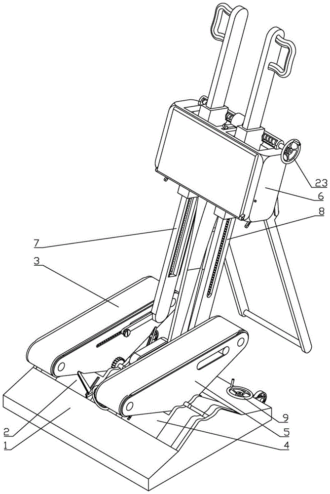
fig. 1 is a schematic view of the overall structure of the present invention.
Fig. 2 is a schematic view of the climbing state of the present invention.
Fig. 3 is an exploded view of the first sliding mechanism, the first traveling mechanism and the first linkage mechanism according to the present invention.
Fig. 4 is a partially enlarged view of the area a in fig. 3 according to the present invention.
FIG. 5 is an exploded view of the connecting knob and locking link of the present invention.
FIG. 6 is a schematic view of the internal structure of the bottom plate of the present invention.
Fig. 7 is a schematic view of the internal structure of the support mechanism of the present invention.
Fig. 8 is a partial enlarged view of the area B in fig. 7 according to the present invention.
FIG. 9 is a schematic view showing the position of the ratchet teeth in the present invention.
FIG. 10 is a schematic view showing the positional relationship between the control driving link, the slide link, the hollow link and the control driven link in the present invention.
FIG. 11 is a schematic view of the pawl and partial ratchet of the present invention.
FIG. 12 is a schematic view of the engagement between the limiting screw and the limiting slider according to the present invention.
In the figure: 1-bottom plate, 2-first sliding mechanism, 3-first traveling mechanism, 4-second sliding mechanism, 5-second traveling mechanism, 6-supporting mechanism, 7-first linkage mechanism, 8-second linkage mechanism, 9-first hand wheel, 10-driving transmission rod, 11-limiting screw rod, 12-limiting slide block, 13-first bidirectional screw rod, 14-adjusting slide block, 15-adjusting connecting rod, 16-control driven rod, 17-first universal block, 18-sliding rod, 19-hollow rod, 20-second universal block, 21-control driving rod, 22-second bidirectional screw rod, 23-second hand wheel, 24-driving gear, 25-worm, 26-motor, 27-tripod, 28-groove, 29-driven roller, 30-driving roller, 31-transmission gear, 32-walking belt, 33-positioning lug, 34-positioning insert block, 35-locking connecting rod, 36-sliding frame, 37-overturning slide block, 38-overturning support rod, 39-first tension spring, 40-driving bevel gear, 41-adjusting screw rod, 42-linkage rod, 43-connecting knob, 44-limiting rectangular block, 45-supporting main body, 46-circular sliding groove, 47-crawling transmission rod, 48-crawling gear, 49-first rack, 50-second rack, 51-positioning rod, 52-operating rod, 53-positioning groove, 54-L-shaped connecting rod, 55-clutch gear, 56-U-shaped frame, 57-supporting support rod, 57-walking belt, 58-ratchet, 59-seat plate, 60-incomplete ratchet, 61-sliding groove, 62-pawl and 63-return spring.
Detailed Description
The following detailed description of the present invention will be made with reference to the accompanying drawings 1-12
Embodiment one, as shown in fig. 1 to 3 and fig. 6, the present invention includes a base plate 1, in order to achieve the purpose of simulating walking uphill or downhill, a first sliding mechanism 2 is slidably connected to the left side in the base plate 1, a first traveling mechanism 3 is provided above the first sliding mechanism 2, the first traveling mechanism 3 is disposed at the upper end of the first sliding mechanism 2 and is separable, a second sliding mechanism 4 is slidably connected to the right side in the base plate 1, a second traveling mechanism 5 is provided above the second sliding mechanism 4, the second traveling mechanism 5 is disposed at the upper end of the second sliding mechanism 4 and is separable, a support mechanism 6 is provided at the front end of the base plate 1, the lower end of the support mechanism 6 is slidably connected to the upper end of the base plate 1, a first linkage mechanism 7 is slidably connected to the left side in the support mechanism 6, the lower end of the first linkage mechanism 7 is slidably connected to the first traveling mechanism 3, the right side in the supporting mechanism 6 is connected with a second linkage mechanism 8 in a sliding mode, the lower end of the second linkage mechanism 8 is connected with a second travelling mechanism 5 in a sliding mode, the bottom plate 1, the supporting mechanism 6, the first linkage mechanism 7 and the second linkage mechanism 8 are matched with each other to form a limiting structure of the height of the first travelling mechanism 3 and the height of the second travelling mechanism 5, therefore, the device can be used for simulating climbing actions, in order to achieve the purpose that the inclination angles of the first travelling mechanism 3 and the second travelling mechanism 5 can be changed through the first sliding mechanism 2 and the second sliding mechanism 4, the front end of the bottom plate 1 is rotatably connected with a first hand wheel 9, the lower end of the first hand wheel 9 is meshed with a driving transmission rod 10, the part of the first hand wheel 9 meshed with the driving transmission rod 10 is in a bevel gear shape, and the first hand wheel 9, the driving transmission rod 10, the first sliding mechanism 2 and the second sliding mechanism 4 are matched with each other to form a limiting structure of the angles of the first travelling mechanism 3 and the second travelling mechanism 5 The utility model discloses a supporting mechanism 6, including bottom plate 1, limiting screw 11, limiting screw 12, supporting mechanism 6, bottom plate 1, limiting screw 11 and limiting slide 12, the purpose that can fix in order to reach supporting mechanism 6 front and back position, the middle part of bottom plate 1 is rotated and is connected with a limiting screw 11, and for the convenience of operation, the rear end of limiting screw 11 is the hand wheel form, and limiting screw 11's outside screw thread cover is equipped with a limiting slide 12, and limiting slide 12's upper end is rotated with supporting mechanism 6 and is connected, and bottom plate 1, limiting screw 11 and limiting slide 12 mutually support and form supporting mechanism 6's limit structure.
In the second embodiment, based on the first embodiment, as shown in fig. 1-3 and fig. 5-6, in order to achieve the purpose of enabling the patient to walk to rehabilitate the limb of the patient during use, the first walking mechanism 3 includes a tripod 27, two grooves 28 are formed at the lower end of the right side of the tripod 27, two driven rollers 29 are respectively rotatably connected to the front and rear ends of the tripod 27, a driving roller 30 is rotatably connected to the lower end of the tripod 27, a transmission gear 31 is fixedly connected to the right side of the driving roller 30, the driving roller 30 is coaxial with the transmission gear 31 and is placed at the upper end of the first sliding mechanism 2, the same walking belt 32 is commonly sleeved between the driving roller 30 and the outer side of each driven roller 29, during use, the driving roller 30 rotates to drive the walking belt 32 to rotate around each driven roller 29, during use, the patient stands at the upper end of the tripod 27, the walking belt 32 slides to enable the patient to walk to keep the position, friction force is provided between the transmission gear 31 and the tripod 27, the walking belt 32 does not slide when the transmission gear 31 is not forced to rotate, in order that the tripod 27 does not rotate or incline when climbing is simulated, a plurality of positioning lugs 33 are arranged inside the right side of the tripod 27, a positioning insert block 34 is connected inside the right side of the tripod 27 in a sliding manner, the right side of the positioning insert block 34 can be meshed with the corresponding positioning lugs 33 when being used in a convex manner to ensure that the position of the positioning insert block 34 cannot move forwards and backwards, a locking connecting rod 35 is connected on the right side of the positioning insert block 34 in a rotating manner, the left end of the locking connecting rod 35 is in a T shape, the locking connecting rod 35 can pull the positioning insert block 34 to slide leftwards and rightwards when being used, in order to avoid the positioning insert block 34 not overturn relative to the tripod 27, a sliding rod is arranged in the tripod 27, the positioning plug block 34 can slide back and forth along the slide bar, and the second traveling mechanism 5 and the first traveling mechanism 3 are the same in structure and are arranged in bilateral symmetry.
Third embodiment, based on the second embodiment, as shown in fig. 1-4 and 6, in order to achieve the purpose of adjusting the walking distance according to the different patients, the first sliding mechanism 2 includes a sliding frame 36, the middle portion of the upper end of the sliding frame 36 is in a groove shape, the left and right sides of the driving roller 30 are respectively placed on the corresponding sides of the upper end of the sliding frame 36, in order to avoid the patients being pinched by the device, a closing plate having the same profile as the upper half portion of the sliding frame 36 is disposed on the left side of the sliding frame 36, a turning slider 37 capable of sliding back and forth along the sliding frame 36 is disposed in the sliding frame 36, the lower end of the turning slider 37 is in a V shape so that it can only slide back and forth along the sliding frame 36, a turning support rod 38 is rotatably connected to the front and rear ends of the turning slider 37, the upper end of each turning support rod 38 can be disposed in the corresponding groove 28, a first tension spring 39 is fixedly connected to the middle portion of each turning support rod 38, the other end of each first tension spring 39 is fixedly connected with the turning slider 37, when in use, the turning slider 37 moves forwards, the turning strut 38 at the front end of the turning slider 37 is arranged in the corresponding groove 28 to push the triangular support 27 to tilt backwards, when the turning slider 37 moves backwards, the turning strut 38 at the rear end of the turning slider 37 is arranged in the corresponding groove 28 to push the triangular support 27 to tilt forwards, the first tension spring 39 is used for resetting the turning strut 38, the front end of the sliding frame 36 is rotatably connected with a driving bevel gear 40, the rear end of the driving bevel gear 40 is meshed with an adjusting screw 41, the front end of the adjusting screw 41 is in a bevel gear shape, the adjusting screw 41 is rotatably connected with the sliding frame 36, the adjusting screw 41 penetrates through the middle part of the turning slider 37 and is in threaded fit with the turning sliding, the driving bevel gear 40 can slide left and right along the driving transmission rod 10 and synchronously rotate with the driving rotation rod, when the driving transmission rod 10 rotates to pass through the driving bevel gear 40, the adjusting screw rod 41 synchronously rotates, the front and back positions of the turnover sliding block 37 are controlled through the adjusting screw rod 41, and the second sliding mechanism 4 is the same as the first sliding mechanism 2 in structure and is arranged in bilateral symmetry.
Fourth embodiment, on the basis of the second embodiment, as shown in fig. 1 to 3 and fig. 5, 7 and 9, in order to achieve the purpose of simulating crawling, the first linkage mechanism 7 includes a linkage rod 42, a connection knob 43 is screwed to the rear end of the linkage rod 42, the connection knob 43 can be slidably connected to the corresponding locking link 35, the left side of the connection knob 43 is in a shape of a tapered groove, so that the locking link 35 can be slid into the left side of the connection knob 43, in order to observe the direction of the tapered groove on the left side of the locking link 35, the right side of the locking link 35 is provided with a marking groove, when the locking link 35 is connected to the connection knob 43, the connection knob 43 and the locking link 35 rotate coaxially, when the marking groove is not required to be observed when the locking link 35 is not required to be separated from the connection knob 43, the tapered groove of the locking link 35 is in a horizontal state, at this time, the locking link 35 and the connection knob 43 are not separated, the lower extreme left side tip of gangbar 42 runs through corresponding tripod 27 and can follow corresponding tripod 27 and slide around, and the lower extreme left side of gangbar 42 is the thickening form, avoids tripod 27 from the lower extreme slippage of gangbar 42, the outside slip cover of gangbar 42 is equipped with a spacing rectangular block 44, produces the slope when avoiding gangbar 42 to slide and causes the dead phenomenon of card, and the front end of gangbar 42 is equipped with the T shape arch, and spacing rectangular block 44 corresponds the bellied position of T shape and offers and the groove that corresponds, second linkage 8 sets up with first linkage 7 the same and bilateral symmetry of structure.
Fifth embodiment, based on the fourth embodiment, as shown in fig. 1-2 and 7-12, in order to achieve the purpose that the climbing height can be adjusted according to the patient, the supporting mechanism 6 includes a supporting main body 45, a plurality of circular sliding slots 46 are formed in the supporting main body 45, each limiting rectangular block 44 is disposed in the corresponding circular sliding slot 46 and can slide left and right along the corresponding circular sliding slot 46, in order to make each linkage rod 42 slide up and down alternatively, two crawling transmission rods 47 are rotatably connected to the middle portion of the supporting main body 45, a crawling gear 48 capable of rotating synchronously with the crawling transmission rods 47 is slidably sleeved on the outer side of each crawling transmission rod 47, a first rack 49 fixedly connected with the first linkage mechanism 7 is engaged on the rear side of the crawling gear 48 on the left side, a second rack 50 fixedly connected with the second linkage mechanism 8 is engaged on the front side of the crawling gear 48 on the right side, the first rack 49 and the second rack 50 are fixedly connected with the corresponding linkage rods 42, the middle part of the upper end of the supporting main body 45 is rotatably connected with a positioning rod 51, the rear end of the positioning rod 51 is rotatably connected with an operating rod 52, the middle part of the supporting main body 45 is provided with a positioning groove 53, the lower end of the operating rod 52 can be twisted into the positioning groove 53 to fix the position of the positioning rod 51, the operating rod 52 and the positioning groove 53 are mutually matched to form a positioning rod 51 limiting structure, the lower end of the positioning rod 51 is rotatably connected with an L-shaped connecting rod 54, the lower end of the L-shaped connecting rod 54 is rotatably connected with a clutch gear 55, the clutch gear 55 can be meshed with each crawling transmission rod 47, the clutch gear 55 only can slide up and down along the supporting main body 45 without generating the phenomenon of left-right sliding, the lower end of the supporting main body 45 is rotatably connected with the limiting slide block 12, and the limiting slide block 12 can push the supporting main body 45 to slide back and forth, when a patient needs to climb to exercise, the limiting slide block 12 needs to be adjusted to a front end limiting position or a rear end limiting position, when the patient needs to walk to exercise, the limiting slide block 12 needs to be adjusted to a middle position of a relative stroke, in order to improve the stability of the device, the rear end of the supporting main body 45 is rotatably connected with a U-shaped frame 56, the left side and the right side of the U-shaped frame 56 are rotatably connected with a supporting support rod 57, the rear end of the supporting main body 45 is provided with a plurality of ratchet teeth 58, each ratchet tooth 58 is integrally formed with the supporting main body 45, each supporting rod 57 is matched with the corresponding ratchet tooth 58 to form a limiting structure of the U-shaped frame 56, when in use, the U-shaped frame 56 is turned to a proper angle, then each supporting rod 57 is turned upwards, the upper end of each supporting rod 57 is placed in the corresponding ratchet tooth 58, and at this time, the U-shaped frame 56 cannot be turned forwards, at this time, the U-shaped frame 56 is not turned backwards under the pressure of the supporting body 45, in order to achieve the purpose of performing rehabilitation training on knee joints of legs of a patient, a seat plate 59 is rotatably connected to the rear side of the supporting body 45, an incomplete ratchet 60 is fixedly connected to each of the left and right sides of the seat plate 59, a sliding groove 61 is formed in each of the left and right sides of the supporting body 45, a pawl 62 capable of sliding left and right along the corresponding sliding groove 61 is arranged in each sliding groove 61, each pawl 62 is capable of being engaged with the corresponding incomplete ratchet 60, a return spring 63 is arranged in each sliding groove 61, when in use, the pawls 62 on the left and right sides are pressed, each pawl 62 is separated from the corresponding incomplete ratchet 60, then the seat plate 59 is turned over to a proper angle manually, then fingers pressing the pawls 62 are released, so that each pawl 62 is engaged with the corresponding incomplete ratchet 60 under the pressure of the corresponding return spring 63, the seat plate 59 is now angularly fixed.
Sixth embodiment, on the basis of the fourth embodiment, as shown in fig. 3, 6, 10 and 12, in order to achieve the purpose of adjusting the width of the device, a first bidirectional screw 13 is rotatably connected to the bottom plate 1, two adjusting sliders 14 are threadedly sleeved on the outer side of the first bidirectional screw 13, the two adjusting sliders 14 have opposite threaded directions and are respectively sleeved on the front side and the rear side of the first bidirectional screw 13, a plurality of adjusting links 15 are rotatably connected to the lower end of each adjusting slider 14, each adjusting link 15 is rotatably connected to a corresponding sliding frame 36, each adjusting link 15, each adjusting slider 14 and the first bidirectional screw 13 are mutually matched to form a limiting structure of the first sliding mechanism 2 and the second sliding mechanism 4, when in use, the first bidirectional screw 13 rotates to enable each adjusting slider 14 to slide in opposite directions, and at this time, the angle of the adjusting link 15 at the lower end of each adjusting slider 14 is changed to enable the distance between the first sliding mechanism 2 and the second sliding mechanism 4 to be adjusted In the change, a control driven rod 16 is engaged at the front end of the first bidirectional screw 13, the control driven rod 16 is rotatably connected with the bottom plate 1, a first universal block 17 is rotatably connected with the upper end of the control driven rod 16, a sliding rod 18 is rotatably connected with the upper end of the first universal block 17, the control driven rod 16, the first universal block 17 and the sliding rod 18 form a universal joint structure, a hollow rod 19 is slidably connected with the upper end of the sliding rod 18, the hollow rod 19 is sleeved outside the sliding rod 18 and rotates coaxially with the sliding rod 18, the hollow rod 19 and the sliding rod 18 do not rotate relatively, a second universal block 20 is rotatably connected with the upper end of the hollow rod 19, the first universal block 17 and the second universal block 20 have the same size and shape, a control driving rod 21 is rotatably connected with the upper end of the second universal block 20, the control driving rod 21, the second universal block 20 and the hollow rod 19 form a universal joint structure, the control active rod 21 is rotatably connected with the support main body 45, the upper end of the control active rod 21 penetrates through the support main body 45, the upper end of the control driving rod 21 is engaged with a second bidirectional screw 22, the upper end of the control driving rod 21 is in a bevel gear shape, the middle part of the second bidirectional screw 22 is sleeved with a bevel gear, the left side and the right side of the second bidirectional screw 22 are respectively in threaded fit with the corresponding limit rectangular blocks 44, a second hand wheel 23 is arranged at the right end of the second bidirectional screw 22, the second hand wheel 23 and the second bidirectional screw 22 are matched with each other to form a limiting structure of the first linkage mechanism 7 and the second linkage mechanism 8, when the bidirectional screw is used, the second hand wheel 23 is rotated to enable the second bidirectional screw 22 to rotate to drive the first linkage mechanism 7 and the second linkage mechanism 8 to change left and right positions, and at the moment, the second bidirectional screw 22 enables the first bidirectional screw 13 to synchronously rotate through controlling the driving rod 21, the hollow rod 19, the sliding rod 18 and the control driven rod 16.
Seventh embodiment, on the basis of the first embodiment, as shown in fig. 3, 6 and 12, in order to achieve a better purpose, a driving gear 24 is rotatably connected in the base plate 1, the driving gear 24 can be meshed with the transmission gear 31, the middle of the driving gear 24 is in a worm-wheel shape, a rotating shaft is fixedly connected in the base plate 1, the driving gear 24 is rotatably sleeved outside the rotating shaft to ensure that the driving gear 24 is not bent when being stressed on the left side and the right side, so as to effectively support the driving gear 24, a worm 25 is meshed at the lower end of the middle of the driving gear 24, a motor 26 is fixedly connected at the rear end of the worm 25, the motor 26 is the prior art, and is not described in more detail herein, in order to facilitate the movement of the device, the front end of the base plate 1 is rotatably connected with a plurality of rollers tangential to the ground, the device is tilted when in use, and the rollers are in contact with the ground, the device can be moved, when the device is horizontally placed, the roller is tangent to the ground, and the position of the device is fixed.
The working process of the invention is as follows: firstly, the device is inclined, the roller wheel is contacted with the ground at the moment, namely, the device can be moved, the device is horizontally placed after the device is moved to a proper position, the roller wheel is tangent with the ground at the moment, the position of the device is fixed, then the U-shaped frame 56 is turned to a proper angle, the upper end of each supporting brace 57 is placed at the lower end of a proper ratchet 58, then the second hand wheel 23 is rotated to enable the second bidirectional screw 22 to rotate to drive the first linkage mechanism 7 and the second linkage mechanism 8 to change left and right positions, at the moment, the second bidirectional screw 22 enables the first bidirectional screw 13 to synchronously rotate through the control driving rod 21, the hollow rod 19, the sliding rod 18 and the control driven rod 16, the first bidirectional screw 13 rotates to enable each adjusting slide block 14 to slide towards opposite directions, at the moment, the angle of the adjusting connecting rod 15 at the lower end of each adjusting slide block 14 is changed to enable the distance between the first sliding mechanism 2 and the second sliding mechanism 4 to change, when the patient needs to do walking exercise, the motor 26 is started, each transmission gear 31 is driven to rotate by the driving gear 24, the driving roller 30 synchronously rotates at the moment, the driving roller 30 rotates to drive the walking belt 32 to rotate around each driven roller 29, the patient stands on the upper end of the tripod 27 when using, the walking belt 32 slides to enable the patient to walk to keep the position, when the patient needs to do walking up-slope or down-slope exercise, the first hand wheel 9 is rotated to enable the driving transmission rod 10 to synchronously rotate, the adjusting screw 41 synchronously rotates when the driving transmission rod 10 rotates through the driving bevel gear 40, the front and back positions of the overturning slide block 37 are controlled by the adjusting screw 41, the overturning slide block 37 moves forwards, the overturning support rod 38 at the front end of the overturning slide block 37 is arranged in the corresponding groove 28 to push the tripod 27 to backwards tilt, when the turning slide block 37 moves backwards, the turning stay bar 38 at the rear end of the turning slide block 37 is placed in the corresponding groove 28 to push the tripod 27 to incline forwards, when a patient needs to do leg knee joint exercise, the pawls 62 at the left and right sides are pressed to separate each pawl 62 from the corresponding incomplete ratchet 60, then the seat plate 59 is turned over manually to a proper angle, then the fingers pressing the pawls 62 are released, each pawl 62 is meshed with the corresponding incomplete ratchet 60 under the pressure of the corresponding return spring 63, the seat plate 59 is fixed in angle at the moment, the patient sits on the seat plate 59, the feet are naturally placed above the corresponding walking belt 32, the lower leg part of the patient rotates frequently to do knee joint exercise along with the sliding of the walking belt 32, when the patient needs to do climbing exercise, the seat plate 59 is folded, then the limiting slide block 12 is adjusted to the front end limit position or the rear end limit position, then adjusting the angle of the U-shaped bracket 56, connecting each locking link 35 with the corresponding connecting knob 43, rotating each connecting knob 43 coaxially with the corresponding locking link 35, then rotating each connecting knob 43 to make the corresponding locking link 35 pull the corresponding positioning insert 34 to move, making one side of each positioning insert 34 mutually engaged with the positioning protrusion at the proper position, then adjusting the tapered tooth groove of the locking link 35 to be horizontal state, at this time, the locking link 35 is not separated from the connecting knob 43, then lifting the first traveling mechanism 3 to the proper height, then pressing the positioning rod 51 downwards, then rotating the operating rod 52 by 90 degrees, at this time, the lower end of the operating rod 52 is placed in the positioning groove 53, while the clutch gear 55 is engaged with each crawling transmission rod 47, then enabling the patient to stand on the upper ends of the first traveling mechanism 3 and the second traveling mechanism 5, the patient holds the upper end of the linkage rod 42 by hands, when the patient treads the first walking mechanism 3 downwards, the first rack 49 enables the left crawling transmission rod 47 to rotate through the left crawling gear 48, the left crawling transmission rod 47 and the clutch gear 55 enable the right crawling transmission rod 47 to drive the right crawling gear 48 to rotate, the right crawling gear 48 enables the second rack 50 to ascend, the position of the second walking mechanism 5 ascends when the linkage rod 42 of the second linkage mechanism 8 ascends, and the first walking mechanism 3 and the second walking mechanism 5 are treaded alternately and repeatedly to enable the patient to achieve the purpose of climbing exercise.
The knee joint exercising device is novel in structure, ingenious in conception and simple and convenient to operate, the purpose of exercising the walking of the patient is effectively achieved through the design, the function of exercising the climbing capacity of the patient is added, the stability of the device is improved, the function of adjusting the left distance and the right distance of the device according to the patient is optimized, the purpose of exercising the knee joint of the patient is achieved, the function of enabling the patient to walk up and down slopes is added, the problem of inconvenience in moving the device is solved, the function of adjusting the climbing height is achieved, and the risk that the patient is injured by clamping is avoided.
Finally, it should be noted that: although the present invention has been described in detail with reference to the foregoing embodiments, it will be apparent to those skilled in the art that changes may be made in the embodiments and/or equivalents thereof without departing from the spirit and scope of the invention. Any modification, equivalent replacement, or improvement made within the spirit and principle of the present invention should be included in the protection scope of the present invention.