Drying and storing integrated wardrobe
Technical Field
The invention belongs to the field of furniture, relates to automatic furniture, and particularly relates to a drying and storing integrated wardrobe.
Background
The wardrobe is generally used for storing clothes, along with the development of cities, the room price rises, the large cities are small in size, the living space is narrow and small, the clothes airing space is limited, after the clothes are washed, airing can not be achieved anytime and anywhere, in addition, the airing is difficult in rainy days in the south, equipment capable of actively drying the clothes is needed, in the prior art, a dryer is generally adopted for drying, but the dryer has several problems, the first problem is that the time is long, the life rhythm of modern people is fast, too long waiting time can not be achieved in many times, the other problem is that the clothes need to be manually put in and taken out, hands can not be liberated, the cost is high, if the wardrobe integrating drying and storing is developed, intelligent home furnishing can be really realized, manual intervention is not needed, and automatic clothes drying and storing can be completed.
Disclosure of Invention
In order to solve the problem that clothes storage and drying cannot be automated in the prior art, the invention provides a drying and storage integrated wardrobe, a lifting type isolation module is utilized to divide the wardrobe into a left storage area and a right drying area, and clothes are directly pushed to the storage area through a clothes storage mechanism after being dried without manual intervention.
In order to solve the technical problems, the technical scheme adopted by the invention is as follows:
the utility model provides a stoving stores integration wardrobe which characterized in that: the clothes drying device comprises a cabinet body, an isolation module and a clothes storage mechanism, wherein the cabinet body is divided into a left storage area and a right drying area through the lifting isolation module, a clothes hanging rod for storing clothes is arranged at the upper part in the cabinet body of the storage area, a clothes drying hanging rod for hanging the clothes to be dried and a shaking device for driving the clothes drying hanging rod to move back and forth are arranged at the top in the cabinet body of the drying area, and the clothes drying hanging rod and the clothes hanging rod are coaxially arranged;
the vibration device is a sine mechanism and comprises a guide rail, a first sliding block, a driving disc, a U-shaped groove and a vibration motor, the guide rail is horizontally fixed at the top in the cabinet body, the first sliding block is installed on the guide rail, the U-shaped groove is fixed on the first sliding block, a sliding groove perpendicular to the direction of the guide rail is formed in the U-shaped groove, the vibration motor is installed on the cabinet body, the driving disc is installed on an output shaft of the vibration motor, and a cylinder extending into the sliding groove is arranged at the eccentric position of the driving disc;
the side wall of the cabinet body below the clothes drying hanging rod is provided with a hot air blower facing to clothes to be dried, and the clothes storage mechanism is used for stirring the clothes on the clothes drying hanging rod to the clothes hanging rod.
Further, the clothes storage mechanism shakes and includes a guide rail, a second slider, a shifting fork, a steering engine and a screw nut mechanism, the guide rail and the shaking device share the guide rail, the second slider is installed on the guide rail and is connected with a nut of the screw nut mechanism, the steering engine is fixedly installed below the second slider, the shifting fork is installed on an output shaft of the steering engine, the second slider is driven to move back and forth along the guide rail through the screw nut mechanism, therefore clothes on a clothes drying hanging rod are stored on the clothes hanging rod, and the output shaft of the steering engine is horizontally arranged and used for lifting the shifting fork to cross obstacles.
Furthermore, the clothes hanging rod is a round rod, the clothes drying hanging rod is a square tube, and an opening at the end part of the square tube is larger than the diameter of the round rod, so that mutual interference between the clothes hanging rod and the round rod is prevented.
Furthermore, be equipped with projection, lifter plate and elevating system on the clothing drying peg, the projection is fixed on the lifter plate, lifter plate and elevating system link to each other, lifter plate and elevating system install together in the clothing drying peg, and clothing drying peg top is equipped with the slide opening that supplies the projection to go up and down, can rise or withdraw from clothing drying peg top through upgrading mechanism drive projection.
Further, keep apart the module and include biax self-locking motor, barrier cloth, fixed plate, reel, two take-up pulleys and two pull wires, biax self-locking motor installs at the internal top of cabinet, and two output shafts of biax self-locking motor link to each other with a take-up pulley through the shaft coupling respectively, the internal bottom of cabinet in the biax self-locking motor below is installed to the reel, the barrier cloth upper end is fixed on the fixed plate, and the lower extreme winding is on the reel, and two pull wire upper ends are fixed respectively on two take-up pulleys, and the lower extreme is installed at the fixed plate both ends, the reel carries out the ascending isolation or the decline roll-up of barrier cloth through reel motor drive and biax self-locking motor cooperation.
Further, the reel passes through guiding mechanism and installs in cabinet body bottom, guiding mechanism includes first deflector and second deflector, reserves the clearance that supplies the spacer fabric to wear out between two deflector tops, and the L type of second deflector lower part for outside buckling reserves installation space for the reel.
Furthermore, the drying area is internally provided with an ironing module, the ironing module comprises an ironing clamping plate, a steam pipeline, a steam generator, a water tank and a direct-current exhaust fan, the ironing clamping plate is arranged on the inner side wall of the cabinet body and used for fixing clothes to be ironed, the inlet of the steam generator is connected with the water tank through a pipeline, the outlet of the steam generator is connected with the steam pipeline, the steam pipeline is arranged in the vertical direction, the steam pipeline is provided with a plurality of small holes opposite to the ironing clamping plate and used for exhausting steam, the water tank is arranged at the bottom in the cabinet body, and the direct-current exhaust fan is arranged on the inner rear side wall of the cabinet body and used for pumping away redundant steam.
Further, the top of the cabinet body in the storage area is also provided with a incense module, the incense module comprises a perfume box, an incense plate, an incense fan, a main shaft, a graduated sheave, a drive plate and a drive plate motor, the perfume box is a circular box body, the perfume box is divided into a plurality of fan-shaped spaces with the same size through partition plates, perfume is placed in each fan-shaped space, the main shaft is installed at the center of the perfume box through a bearing, the incense plate is fixed on the main shaft at the upper end and the lower end of the perfume box, a fan-shaped opening is arranged on the incense plate, when the fan-shaped opening corresponds to the fan-shaped spaces, perfume in the corresponding fan-shaped spaces is released, the graduated sheave is fixed at the upper end of the main shaft, the graduated sheave is provided with graduated grooves corresponding to the number of the fan-shaped spaces, the drive shaft for driving the graduated sheave is arranged on the drive plate, the drive plate is connected with the drive plate motor, and the incense fan is installed above the perfume box through a connecting piece, provides wind power for incense.
Further, the cabinet body comprises roof, bottom plate and left and right sides curb plate, and cabinet body front side is equipped with the slidingtype and moves the door, and the internal top baffle and the bottom plate baffle that are used for erection equipment that are equipped with of cabinet.
The invention has the following beneficial effects:
the clothes storage device divides the interior of the clothes storage device into a storage area on the left side and a drying area on the right side by using the lifting type isolation module, and clothes are directly pushed to the storage area through the clothes storage mechanism after being dried without manual intervention. The invention designs the sine mechanism, and the sine mechanism drives the dried clothes to vibrate back and forth, so that firstly, the drying speed can be accelerated, but the clothes can be wrinkle-removed, and the clothes naturally become flat in the shaking process.
Drawings
The invention is further explained below with reference to the figures and inventive examples.
FIG. 1 is an overall schematic view of the drying and storage integrated wardrobe of the present invention.
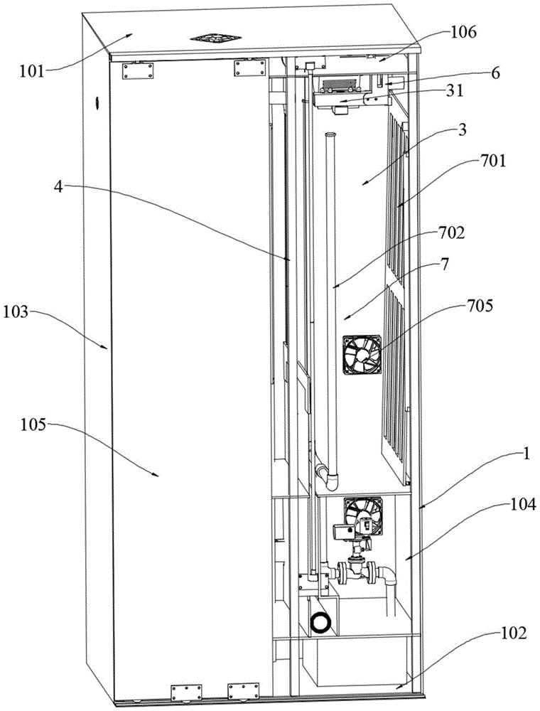
FIG. 2 is a schematic view of the drying and storing integrated wardrobe with the sliding door removed.
FIG. 3 is a schematic view of the drying and storing integrated wardrobe with the sliding door, the top plate and the right side plate removed.
FIG. 4 is a schematic view showing the installation relationship between the clothes-storing mechanism and the shaking device.
FIG. 5 is a schematic view of the shaking device and clothes drying hanger of the present invention.
Fig. 6 is an internal cross-sectional view of a clothes drying hanging rod of the present invention.
Figure 7 is a schematic view of the structure of the steam duct of the ironing module.
FIG. 8 is a schematic view of an isolation module according to the present invention.
FIG. 9 is a schematic view of the incense module of the present invention.
FIG. 10 is an exploded view of the incense module of the present invention,
FIG. 11 is a schematic view of the dial of the incense module of the present invention.
1-cabinet body, 101-top plate, 102-bottom plate, 103-left side plate, 104-right side plate, 105-sliding door, 106-top partition plate, 107-middle partition plate, 108-bottom partition plate, 109-back side plate, 2-storage area, 21-clothes hanging rod, 3-drying area, 31-clothes drying hanging rod, 311-convex column, 312-lifting plate, 313-screw nut lifting sliding table, 314-sliding hole, 4-isolation module, 401-double-shaft self-locking motor, 402-isolation cloth, 403-fixing plate, 404-winding drum, 405-winding wheel, 406-traction line, 407-first guide plate, 408-second guide plate, 409-winding drum motor, 410-synchronous belt, 5-clothes storage mechanism, 501-second slide block, 502-shifting fork, 503-steering engine, 504-lead screw, 505-lead screw nut, 506-lead screw motor, 6-shaking device, 601-guide rail, 602-first sliding block, 603-driving disk, 604-U-shaped groove, 605-shaking motor, 606-bending piece, 7-ironing module, 701-ironing clamping plate, 702-steam pipeline, 703-steam generator, 704-water tank, 705-direct current exhaust fan, 706-clamp, 8-incense module, 801-perfume box, 802-incense plate, 803-incense fan, 804-main shaft, 805-indexing, 806-dial plate, 807-dial plate motor, 808-sector opening, 809-dial shaft and 9-hot air blower.
Detailed Description
Embodiments of the present invention will be described in further detail with reference to the drawings and examples. The following examples are intended to illustrate the invention but are not intended to limit the scope of the invention.
As shown in fig. 1 to 11, the drying and storing integrated wardrobe comprises a wardrobe body 1, an isolation module 4 and a clothes storage mechanism 5, wherein the wardrobe body 1 is composed of a top plate 101, a rear side plate 109, a bottom plate 102, a left side plate and a right side plate 104, a sliding type sliding door 105 is arranged on the front side of the wardrobe body 1, and a top partition plate 106, a middle partition plate 107 and a bottom partition plate 108 for installing equipment are arranged in the wardrobe body 1. The cabinet body 1 is divided into a left storage area 2 and a right drying area 3 through a lifting isolation module 4, a clothes hanging rod 21 for storing clothes is arranged at the upper part in the cabinet body 1 of the storage area 2, the specific clothes hanging rod 21 is fixed on a left side plate 103 and a top partition plate 106 through a connecting piece, a clothes drying hanging rod 31 for hanging clothes to be dried and a shaking device 6 for driving the clothes drying hanging rod 31 to move back and forth are arranged at the top in the cabinet body 1 of the drying area 3, and the clothes drying hanging rod 31 and the clothes hanging rod 21 are coaxially arranged;
as shown in fig. 4 and 5, the shaking device 6 is a sine mechanism, and includes a guide rail 601, a first slider 602, a driving disc 603, a U-shaped groove 604 and a shaking motor 605, the guide rail 601 is horizontally fixed at the bottom of the top partition 106, and spans across the left storage area 2 and the right drying area 3, the first slider 602 is installed on the guide rail 601, the clothes drying hanging rod 31 is hung on the first slider 602 through a bending piece 606, the U-shaped groove 604 is fixed on the first slider 602, a sliding groove perpendicular to the direction of the guide rail 601 is arranged on the U-shaped groove 604, the shaking motor 605 is installed on the top plate 101 of the cabinet 1, the driving disc 603 is installed on the output shaft of the shaking motor 605, and a cylinder (not shown in the drawing) extending into the sliding groove is arranged at an eccentric position on the driving disc 603;
as shown in fig. 3, a hot air blower 9 facing the clothes to be dried is disposed on the sidewall of the cabinet 1 below the clothes drying hanging rod 31, and the clothes storage mechanism 5 is used for shifting the clothes on the clothes drying hanging rod 31 to the clothes hanging rod 21.
As shown in fig. 4, the clothes storage mechanism 5 includes a guide rail 601, a second slider 501, a shifting fork 502, a steering gear 503 and a screw nut mechanism, the screw nut mechanism includes a screw 504, a screw nut 505 and a screw motor 506 which are connected in sequence, the guide rail 601 and the shaking device 6 share one guide rail 601, the second slider 501 is mounted on the guide rail 601 and connected with the screw nut 505 of the screw nut mechanism, the steering gear 503 is fixedly mounted below the second slider 501, the shifting fork 502 is mounted on an output shaft of the steering gear 503, the second slider 501 is driven by the screw nut 505 mechanism to move back and forth along the guide rail 601, so that clothes on the clothes drying hanging rod 31 are stored on the clothes hanging rod 21, and the output shaft of the steering gear 503 is horizontally arranged and used for rotating and lifting up and over obstacles the shifting fork 502.
In the embodiment of the present invention, the clothes hanging rod 21 is a round rod, the clothes drying hanging rod 31 is a square tube, the opening of the end of the square tube is larger than the diameter of the round rod, so that the vibration device 6 can prevent the interference between the clothes hanging rod 21 and the clothes hanging rod 31 when driving the clothes drying hanging rod 31 to move back and forth, and the operation can be smoothly performed when the hanger hook is moved by the shifting fork 502 of the clothes storage mechanism 5 from the clothes drying hanging rod 31.
As shown in fig. 5 and 6, a convex column 311, a lifting plate 312 and a lead screw nut lifting slide table 313 are arranged on the clothes drying hanging rod 31, the convex column 311 is fixed on the lifting plate 312, the lifting plate 312 is connected with the lead screw nut lifting slide table 313, the lifting plate 312 and the lead screw nut lifting slide table 313 are installed in the clothes drying hanging rod 31 together, a slide hole 314 for lifting the convex column 311 is formed in the top of the clothes drying hanging rod 31, the convex column 311 can be driven by an upgrading mechanism to be lifted or retracted from the top of the clothes drying hanging rod 31, when the convex column 311 is lifted, firmness of clothes hung on the clothes drying hanging rod 31 can be improved, the clothes can be prevented from falling off in the vibration process, and when the convex column 311 is retracted, the clothes can be very conveniently shifted to the clothes hanging rod 21 from the clothes drying hanging rod 31 by the shifting fork 502.
As shown in fig. 2, 3, and 8, the isolation module 4 includes a dual-axis self-locking motor 401, an isolation cloth 402, a fixing plate 403, a winding drum 404, two winding wheels 405, and two pulling wires 406, the dual-axis self-locking motor 401 is installed at the top inside the cabinet body 1, two output shafts of the dual-axis self-locking motor 401 are respectively connected to one winding wheel 405 through a coupling, the winding drum 404 is installed on the bottom partition 108 below the dual-axis self-locking motor 401, the upper end of the isolation cloth 402 is fixed on the fixing plate 403, the lower end of the isolation cloth is wound on the winding drum 404, the upper ends of the two pulling wires 406 are respectively wound and fixed on the two winding wheels 405, the lower ends of the fixing plate 403 are installed at both ends, and the winding drum 404 is driven by the winding drum motor 409 to cooperate with the dual-axis self-locking motor 401 to perform the ascending isolation or descending winding of the isolation cloth 402.
In the embodiment of the invention, as shown in fig. 2, the winding drum 404 is installed at the bottom of the cabinet body 1 through a guide mechanism, the guide mechanism includes a first guide plate 407 and a second guide plate 408, a gap for the isolation cloth 402 to penetrate out is reserved between the tops of the two guide plates, the lower portion of the second guide plate 408 is an outward bent L-shaped structure, an installation space is reserved for the winding drum 404, the winding drum 404 is connected with a winding drum motor 409 through a synchronous belt, and the winding drum 404 is driven to rotate by the winding drum motor 409 so as to keep the isolation cloth 402 being wound and unwound synchronously.
As shown in fig. 2, an ironing module 7 is further disposed in the drying zone 3, the ironing module 7 includes an ironing card 701, a steam pipe 702, a steam generator 703, a water tank 704 and a direct-flow exhaust fan 705, the ironing card 701 is disposed on an inner side wall of the cabinet 1, specifically on the right side plate 104, a plurality of clamps 706 for fixing clothes to be ironed are further disposed on the ironing card 701, an inlet of the steam generator 703 is connected to the water tank 704 through a pipe, the water tank 704 is fixed on the bottom plate 102 in the cabinet 1, an outlet of the steam generator 703 is connected to the steam pipe 702, the steam pipe 702 is disposed in a vertical direction, a plurality of small holes for exhausting steam facing the ironing card 701 are disposed on the steam pipe 702, the water tank 704 is mounted at an inner bottom of the cabinet 1, the direct-flow exhaust fan 705 is mounted on the rear side plate 109 in the cabinet 1 for exhausting excess steam, the rear plate 109 is provided with an exhaust hole at a position where the dc exhaust fan is installed.
As shown in fig. 2, a fragrance module 8 is further disposed on the top of the cabinet 1 in the storage area 2, as shown in fig. 9, 10 and 11, the fragrance module 8 includes a fragrance box 801, a fragrance plate 802, a fragrance fan 803, a main shaft 804, a dividing grooved wheel 805, a dial 806 and a dial motor 807, the fragrance box 801 is a circular box body, the fragrance box 801 is divided into a plurality of sector spaces with the same size by partition plates, a fragrance is placed in each sector space, the main shaft 804 is mounted at the center of the fragrance box 801 through a bearing, the fragrance plate 802 is fixed on the main shaft 804 at the upper and lower ends of the fragrance box 801, a sector opening 808 is disposed on the fragrance plate 802, when the sector opening 808 corresponds to the sector spaces, the fragrance in the corresponding sector spaces is released, the dividing grooved wheel 805 is fixed at the upper end of the main shaft 804, the dividing grooved wheel 805 is provided with dividing grooves corresponding to the number of the sector spaces, a dial 809 for driving the dividing grooved wheel 805 is disposed on the dial 806, the dial plate 806 is connected with a dial plate motor 807, and the incense fan 803 is arranged above the incense box 801 through a connecting piece to provide wind power for incense. For example, in the embodiment of the present invention, the fragrance box 801 is equally divided into four fan-shaped spaces, the fragrance plate 802 is provided with a fan-shaped opening 808 corresponding to one fan-shaped space, the indexing grooved wheel 805 is a four-degree grooved wheel, when the dial motor 807 drives the dial 806 to rotate, the dial 806 drives the four-degree grooved wheel to rotate through the dial shaft 809 thereon, the fan-shaped opening 808 on the fragrance plate 802 corresponds to one fan-shaped space when rotating 90 degrees every time, and fragrance in the corresponding fan-shaped space can be blown out through the fragrance fan 803.
The using method of the invention is as follows: under normal conditions, the isolation module 4 is pulled up, divide into storage area 2 on the left side and the drying area 3 on the right side in the cabinet body 1, the clothing pole 21 of storage area 2 is used for hanging the storage clothing, when needing to dry after having washed by the clothing, hang the clothing that needs to dry on the clothing peg 31 through the clothes hanger, start shaking device 6 and air heater 9, also can start the direct current exhaust fan simultaneously and remove steam, the clothing that hangs on the clothing peg 31 vibrates along with the vibration of making a round trip of clothing peg 31, accelerate the clothing speed of drying. The convex column 311 on the clothes drying hanging rod 31 can effectively prevent clothes from falling off due to vibration, when the clothes drying is finished, whether the ironing module 7 is started or not is selected according to needs, if ironing is needed, the dried clothes is shifted to the right side to be close to the ironing clamping plate 701 on the right side plate 104, whether the clothes are fixed on the ironing clamping plate 701 by the clamp 706 is selected according to needs, the steam generator 703 is started to generate steam, the generated steam is uniformly sprayed to the clothes to be ironed through the steam pipeline 702, and meanwhile, the redundant steam is sucked and discharged by the direct-current exhaust fan. When ironing is finished or clothes do not need to be ironed and need to be stored, firstly, the isolation module 4 is started, the isolation cloth 402 is lowered, the clothes storage mechanism 5 is started, the shifting fork 502 is driven by the screw nut 505 mechanism to move towards the right side to reach the drying area 3, in the moving process, the steering gear 503 rotates, the shifting fork 502 is lifted upwards to enable the shifting fork 502 to cross a clothes rack on the clothes drying hanging rod 31 to reach the right side of the clothes rack, the steering gear 503 overturns, the shifting fork 502 rotates downwards to fork two sides of the clothes drying hanging rod 31, meanwhile, the lifting mechanism is started to drive the lifting plate 312 and the convex column 311 to descend, the convex column 311 is retracted into the clothes drying hanging rod 31, the screw nut 505 mechanism rotates reversely to drive the shifting fork 502 to move towards the left, the shifting fork 502 stirs the clothes rack on the clothes drying hanging rod 31 to stir the dried clothes onto the clothes hanging rod 21 to finish clothes storage, then, the isolation module 4 is started, the isolation cloth 402 is pulled up, each device is reset, waiting for the next clothes drying.
The incense module 8 can be started regularly or irregularly, and different spices can be blown to the stored clothes intermittently to carry out the aromatherapy.
The above embodiments are merely illustrative of the present invention and are not to be construed as limiting the invention. Although the present invention has been described in detail with reference to the embodiments, it should be understood by those skilled in the art that various combinations, modifications or equivalents may be made to the technical solution of the present invention without departing from the spirit and scope of the technical solution of the present invention, and the technical solution of the present invention is covered by the claims of the present invention.