CN113104155B - Anti-misoperation cable releasing device for cable releasing hook - Google Patents
Anti-misoperation cable releasing device for cable releasing hook Download PDFInfo
- Publication number
- CN113104155B CN113104155B CN202110472506.2A CN202110472506A CN113104155B CN 113104155 B CN113104155 B CN 113104155B CN 202110472506 A CN202110472506 A CN 202110472506A CN 113104155 B CN113104155 B CN 113104155B
- Authority
- CN
- China
- Prior art keywords
- alarm
- fixedly connected
- block
- electric telescopic
- sides
- Prior art date
- Legal status (The legal status is an assumption and is not a legal conclusion. Google has not performed a legal analysis and makes no representation as to the accuracy of the status listed.)
- Active
Links
Images



Classifications
-
- B—PERFORMING OPERATIONS; TRANSPORTING
- B63—SHIPS OR OTHER WATERBORNE VESSELS; RELATED EQUIPMENT
- B63B—SHIPS OR OTHER WATERBORNE VESSELS; EQUIPMENT FOR SHIPPING
- B63B21/00—Tying-up; Shifting, towing, or pushing equipment; Anchoring
- B63B21/04—Fastening or guiding equipment for chains, ropes, hawsers, or the like
-
- G—PHYSICS
- G08—SIGNALLING
- G08B—SIGNALLING SYSTEMS, e.g. PERSONAL CALLING SYSTEMS; ORDER TELEGRAPHS; ALARM SYSTEMS
- G08B21/00—Alarms responsive to a single specified undesired or abnormal condition and not otherwise provided for
- G08B21/18—Status alarms
- G08B21/187—Machine fault alarms
-
- G—PHYSICS
- G08—SIGNALLING
- G08B—SIGNALLING SYSTEMS, e.g. PERSONAL CALLING SYSTEMS; ORDER TELEGRAPHS; ALARM SYSTEMS
- G08B7/00—Signalling systems according to two or more of groups G08B3/00 - G08B6/00
- G08B7/06—Signalling systems according to two or more of groups G08B3/00 - G08B6/00 using electric transmission, e.g. involving audible and visible signalling through the use of sound and light sources
Landscapes
- Physics & Mathematics (AREA)
- General Physics & Mathematics (AREA)
- Business, Economics & Management (AREA)
- Emergency Management (AREA)
- Chemical & Material Sciences (AREA)
- Engineering & Computer Science (AREA)
- Combustion & Propulsion (AREA)
- Mechanical Engineering (AREA)
- Ocean & Marine Engineering (AREA)
- Road Signs Or Road Markings (AREA)
Abstract
The invention discloses an anti-misoperation cable releasing device for a cable releasing hook, which comprises a cable releasing hook body and two side plates, wherein the end part of the cable releasing hook body is welded with a connecting shaft, the cable releasing hook body is rotatably connected between the two side plates through the connecting shaft, the surfaces of the two side plates, which are relatively far away, are welded with fixed blocks, and the sides, which are relatively far away, of the two fixed blocks are welded with side rods, so that the anti-misoperation cable releasing device for the cable releasing hook has the following beneficial effects that: the invention is provided with the limiting mechanism, after the disengaging hook body is rotated to a certain angle, the two limiting blocks of the limiting mechanism are inserted into the opposite limiting holes, so that one end of the disengaging hook body can be fixed, the disengaging hook body is prevented from continuing to rotate, the locking is very convenient and very stable.
Description
The technical field is as follows:
the invention belongs to the technical field of a disengaging hook, and particularly relates to an anti-misoperation disengaging device for the disengaging hook.
Background art:
the mooring rope releasing hook is a main mooring rope releasing tool of a mooring rope releasing mechanism for a large wharf, the end part of a mooring rope can be hung on the mooring rope releasing hook, when emergency conditions such as fire hazard and the like happen to the wharf or a ship, the mooring rope can be released from the mooring rope through operating a handle by an operator, the mooring rope can be quickly unhooked and released, and a ship body can quickly leave the wharf, so that the safety of the wharf and the ship is ensured, and huge loss is avoided.
Under the prior art, when the release hook is used, the locking mechanism is generally controlled manually through a handle, the locking is not convenient and stable enough, the risk of cable release by mistake is easy to occur, and the safety potential hazard is very large.
The invention content is as follows:
the invention aims to solve the problems, and provides an anti-misoperation cable release device for a cable release hook, which solves the problems that when the cable release hook is used, a locking mechanism is generally manually controlled through a handle, the locking is not convenient and stable enough, the risk of cable release by mistake is easy to occur, and the cable release hook has great potential safety hazard.
In order to solve the above problems, the present invention provides a technical solution:
an anti-misoperation cable release device for a cable release hook comprises a cable release hook body and two side plates, wherein two side plates are welded at the end part of the cable release hook body, the cable release hook body is rotatably connected between the two side plates through a connecting shaft, fixed blocks are welded on the surface of one side, which is far away from the two side plates, of the two fixed blocks, side rods are welded on the side, which is far away from the two fixed blocks, of the two side rods, a connecting rod is fixedly connected between the ends, far away from the side plates, of the two side rods, a limiting mechanism is arranged inside the connecting rod, the limiting mechanism comprises a motor, the motor is fixedly connected to one end inside the connecting rod through a fixed seat, the output end of the motor is fixedly connected with a double-end lead screw, one end, far away from the motor, of the double-end lead screw is rotatably connected to the inner wall of the connecting rod through a bearing, and moving rods are in threaded connection with the two ends of the double-end lead screw, the upper end of the connecting rod is provided with an opening, the upper end of each moving rod penetrates through the opening at the upper end of the connecting rod, one side of each moving rod, which is close to the side plate, is welded with a supporting rod, one side of each supporting rod, which is close to each other, is fixedly connected with a limiting block, two sides of one end of the cable releasing hook body, which is close to the connecting rod, are provided with limiting holes, and each limiting block is inserted into the corresponding limiting hole;
the cable release hook comprises a body, a middle hole is formed in the body and located between two limiting holes, the middle of the middle hole is fixedly connected with a middle block, alarm mechanisms are arranged on two sides of the middle block and respectively comprise springs which are fixedly connected to the surfaces of the middle parts of the two sides of the middle block respectively, an alarm switch is fixedly connected to two sides of one end of the middle block, an electric telescopic rod switch is fixedly connected to two sides of one end, away from the alarm switch, of the middle block, an alarm pressing block is arranged on one side, away from the alarm switch relatively, of the middle block in a pressed mode, an electric telescopic rod pressing block is arranged on one side, away from the middle block, of the two electric telescopic rod switches in a pressed mode, a fixed rod is fixedly connected to one side, away from the middle block, of the alarm pressing block and the electric telescopic rod pressing block, an ejector rod is fixedly connected to one end, away from the springs, of the fixed rod is fixedly connected to two ends, away from the ejector rod relatively, close to the ejector rod, of the ejector rod is fixedly connected to two ends of the two ejector rod sides, away from the ejector rod mutually One end of each of the two ejector rods, which is far away from each other, is in contact with the surface of the corresponding limiting block;
one of them curb plate surface is provided with the siren, the siren passes through bolt fixed connection in the surface of curb plate, the siren is audible-visual annunciator, siren and the equal electric connection of every siren switch.
Preferably, the one end both sides that the connecting rod was kept away from to the disengaging hook body all are provided with the strengthening mechanism, the strengthening mechanism includes electric telescopic handle, two the one end that electric telescopic handle kept away from each other is respectively through bolt fixed connection in the side surface that two curb plates are close to each other, two electric telescopic handle's output fixedly connected with inserted block, the jack has all been seted up to the relative inserted block in both sides surface of disengaging hook body, every the inserted block all pegs graft in the jack that corresponds, electric telescopic handle all with every electric telescopic handle switch electric connection.
Preferably, two the lower extreme of carriage release lever sliding connection respectively in the inside both sides of connecting rod, the stopper is the cuboid, every spacing hole all matches with relative stopper.
Preferably, the insert blocks are hexagonal prism type, and each insert hole is matched with the corresponding insert block.
The beneficial effects of the invention include:
1. the invention is provided with the limiting mechanism, after the disengaging hook body rotates to a certain angle, one end of the disengaging hook body can be fixed by inserting the two limiting blocks of the limiting mechanism into the opposite limiting holes, the disengaging hook body is prevented from continuing to rotate, and the locking is very convenient and very stable.
2. The invention is provided with the alarm mechanism, when a certain limiting block is not fixed stably and is separated from the limiting hole, the alarm switch of the alarm mechanism is opened, the alarm is opened, and the alarm is an audible and visual alarm, so that the limiting block and the limiting hole can be reminded to loosen by workers, and the maintenance is convenient in time.
3. The invention is provided with the reinforcing mechanism, when a certain limiting block is not fixed stably and is separated from the limiting hole, the output ends of two electric telescopic rods of the reinforcing mechanism extend to drive the insertion blocks to be inserted into the opposite insertion holes, so that the disengaging hook body can be fixed in time, and the disengaging hook body is prevented from rotating to cause cable disengaging by mistake.
Description of the drawings:
for ease of illustration, the invention is described in detail by the following detailed description and the accompanying drawings.
FIG. 1 is a schematic top sectional view of the present invention;
FIG. 2 is a sectional structure diagram of the joint of the limiting block of the present invention;
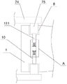
FIG. 3 is an enlarged schematic view of the structure at A of the present invention;
FIG. 4 is a schematic side view of the present invention;
fig. 5 is a schematic structural view of the joint of the electric telescopic rod of the present invention.
In the figure: 1. a release hook body; 2. a side plate; 3. a connecting shaft; 4. a fixed block; 5. a side lever; 6. a connecting rod; 7. a limiting mechanism; 71. a motor; 72. a double-end screw rod; 73. a travel bar; 74. a support bar; 75. a limiting block; 8. a limiting hole; 9. a reinforcement mechanism; 91. an electric telescopic rod; 92. inserting a block; 10. a mesopore; 11. an alarm mechanism; 111. a top rod; 112. a spring; 113. fixing the rod; 114. alarm per block; 115. an alarm switch; 116. an electric telescopic rod pressing block; 117. an electric telescopic rod switch; 12. a jack; 13. a middle block; 14. an alarm.
The specific implementation mode is as follows:
as shown in fig. 1 to 5, the following technical solutions are adopted in the present embodiment: an anti-misoperation cable release device for a cable release hook comprises a cable release hook body 1 and side plates 2, wherein the side plates 2 are provided with two, a connecting shaft 3 is welded at the end part of the cable release hook body 1, the cable release hook body 1 is rotatably connected between the two side plates 2 through the connecting shaft 3, fixed blocks 4 are welded on the surfaces of the opposite far sides of the two side plates 2, side rods 5 are welded on the opposite far sides of the two fixed blocks 4, a connecting rod 6 is fixedly connected between the far ends of the two side rods 5 away from the side plates 2, a limiting mechanism 7 is arranged inside the connecting rod 6, the limiting mechanism 7 comprises a motor 71, the motor 71 is fixedly connected with one end inside the connecting rod 6 through a fixed seat, a double-end lead screw 72 is fixedly connected with the output end of the motor 71, one end of the double-end lead screw 72, which is far away from the motor 71, is rotatably connected with the inner wall of the connecting rod 6 through a bearing, and moving rods 73 are in threaded connection with the two ends of the double-end lead screw 72, an opening is formed in the upper end of the connecting rod 6, the upper ends of the moving rods 73 penetrate through the opening in the upper end of the connecting rod 6, one side, close to the side plate 2, of each moving rod 73 is welded with a supporting rod 74, one side, close to each other, of each supporting rod 74 is fixedly connected with a limiting block 75, two sides, close to the connecting rod 6, of one end of the disengaging hook body 1 are respectively provided with a limiting hole 8, each limiting block 75 is inserted into the corresponding limiting hole 8, a motor 71 of a limiting mechanism 7 is opened, the motor 71 rotates to drive a double-end lead screw 72 to rotate, the moving rods 73 at two ends relatively move when the double-end lead screw 72 rotates to drive the limiting blocks 75 on the moving rods 73 to be relatively close to each other, so that the limiting blocks 75 are inserted into the corresponding limiting holes 8, one end of the disengaging hook body 1 can be fixed, the disengaging hook body 1 is prevented from continuing to rotate, and locking is very convenient;
the middle hole 10 is arranged in the disengaging hook body 1 and between the two limiting holes 8, the middle part of the middle hole 10 is fixedly connected with a middle block 13, both sides of the middle block 13 are provided with alarm mechanisms 11, each alarm mechanism 11 comprises a spring 112, the two springs 112 are respectively and fixedly connected with the middle surface of both sides of the middle block 13, both sides of one end of the middle block 13 are respectively and fixedly connected with an alarm switch 115, both sides of one end of the middle block 13 far away from the alarm switch 115 are respectively and fixedly connected with an electric telescopic rod switch 117, the opposite far sides of the two alarm switches 115 are respectively and fixedly connected with an alarm pressing block 114, the far sides of the two electric telescopic rod switches 117 are respectively and fixedly connected with an electric telescopic rod pressing block 116, the far sides of each alarm pressing block 114 and the electric telescopic rod pressing block 116 far away from the middle block 13 are respectively and fixedly connected with a fixing rod 113, and one far ends of the two springs 112 are respectively and fixedly connected with a push rod 111, one end of the pair of fixed rods 113, which is relatively far away from each other, is fixedly connected to two sides of one end of the two push rods 111, which is close to each other, respectively, one end of the two push rods 111, which is relatively far away from each other, is in surface contact with the corresponding limiting block 75, the alarm 14 is arranged on the surface of one side plate 2, the alarm 14 is fixedly connected to the surface of the side plate 2 through a bolt, the alarm 14 is an audible and visual alarm, the alarm 14 is electrically connected with each alarm switch 115, when the two limiting blocks 75 are inserted into the corresponding limiting holes 8, the push rods 111 of the alarm mechanism 11 are pressed, the two push rods 111 are pressed and moved into the central hole 10, the alarm pressing blocks 114 on the two fixed rods 113 are driven to press the alarm switches 115, when one limiting block 75 is not fixedly separated from the limiting hole 8, the alarm pressing blocks 114 on the opposite fixed rods 113 are separated from the contact with the alarm switches 115, and the alarm switches 115 are opened, the alarm 14 is opened along with the limit hole, the alarm 14 is an audible and visual alarm and can remind workers that the limit block 75 is not flexible with the limit hole 8, and timely maintenance is facilitated.
Wherein, both sides of one end of the disengaging hook body 1 far away from the connecting rod 6 are provided with the reinforcing mechanisms 9, the reinforcing mechanisms 9 comprise electric telescopic rods 91, the mutually far ends of the two electric telescopic rods 91 are respectively fixedly connected with one side surface of the two side plates 2 close to each other through bolts, the output ends of the two electric telescopic rods 91 are fixedly connected with insertion blocks 92, the opposite insertion blocks 92 on the two side surfaces of the disengaging hook body 1 are respectively provided with insertion holes 12, each insertion block 92 is inserted into the corresponding insertion hole 12, the electric telescopic rods 91 are electrically connected with each electric telescopic rod switch 117, when a certain limit block 75 is not fixedly and stably separated from the limit hole 8, the electric telescopic rods on the opposite fixing rods 113 are separated from the contact with the electric telescopic rod switches 117 according to the blocks 116, the electric telescopic rod switches 117 are opened, the output ends of the two electric telescopic rods 117 extend to drive the insertion blocks 92 to be inserted into the opposite insertion holes 12, the two insertion blocks 92 can fix the release hook body 1 in time, and the phenomenon that the release hook body 1 rotates to cause cable release by mistake is avoided.
The plug blocks 92 are hexagonal prism-shaped, each plug hole 12 is matched with the corresponding plug block 92, and the hexagonal prism-shaped plug blocks 92 are plugged into the plug holes 12 to limit the rotation of the release hook body 1.
Wherein, the lower extreme of two carriage release levers 73 is sliding connection respectively in the inside both sides of connecting rod 6, and stopper 75 is the cuboid, and every spacing hole 8 all matches with relative stopper 75, and the stopper 75 of cuboid is pegged graft in spacing hole 8, can restrict the rotation of disengaging hook body 1.
Specifically, the method comprises the following steps: when the device is used, one end of a cable is firstly sleeved on a disengaging hook body 1, the disengaging hook body 1 is rotated to a certain angle, a motor 71 of a limiting mechanism 7 is opened, the motor 71 rotates to drive a double-end lead screw 72 to rotate, moving rods 73 at two ends relatively move when the double-end lead screw 72 rotates to drive limiting blocks 75 on the moving rods 73 to relatively approach, so that the limiting blocks 75 are inserted in opposite limiting holes 8, one end of the disengaging hook body 1 can be fixed, the disengaging hook body 1 is prevented from continuously rotating, the locking is very convenient, two limiting blocks 75 are inserted in corresponding limiting holes 8 at the moment, ejector rods 111 of an alarm mechanism 11 can be extruded, the two ejector rods 111 are extruded and moved to the inside of a middle hole 10, alarm pressing blocks 114 on two fixing rods 113 are driven to press alarm switches 115, electric telescopic rod pressing blocks 116 on the other two fixing rods 113 are driven to press electric telescopic rod switches 117, alarm switch 115 is in the off-state this moment with electric telescopic handle switch 117, when there is certain stopper 75 fixed insecure to break away from spacing hole 8, the alarm on relative dead lever 113 is pressed piece 114 and is broken away from the contact with alarm switch 115, alarm switch 115 is opened, alarm 14 is opened thereupon, alarm 14 is audible-visual annunciator, can remind staff's stopper 75 not hard up with spacing hole 8, the convenience is overhauld in time, electric telescopic handle on relative dead lever 113 presses piece 116 and breaks away from the contact with electric telescopic handle switch 117 simultaneously, electric telescopic handle 117 switch is opened, the output extension of two electric telescopic handle 117 drives in the inserted block 92 inserts relative jack 12, two inserted blocks 92 can in time fix and stay release hook body 1, avoid release hook body 1 to rotate and lead to the mistake to release the cable.
While there have been shown and described what are at present considered to be the fundamental principles of the invention and its essential features and advantages, it will be understood by those skilled in the art that the invention is not limited by the embodiments described above, which are merely illustrative of the principles of the invention, but that various changes and modifications may be made therein without departing from the spirit and scope of the invention as defined by the appended claims and their equivalents.
Claims (4)
1. The utility model provides a disengaging hook is with preventing mistake cable release device, includes disengaging hook body (1) and curb plate (2), its characterized in that, curb plate (2) are provided with two, the tip welding of disengaging hook body (1) has connecting axle (3), disengaging hook body (1) rotates through connecting axle (3) and connects between two curb plates (2), two one side surface that curb plate (2) kept away from relatively all welds fixed block (4), two one side that fixed block (4) kept away from relatively all welds side lever (5), two fixedly connected with connecting rod (6) between the one end that curb plate (2) were kept away from to side lever (5), the inside of connecting rod (6) is provided with stop gear (7), stop gear (7) include motor (71), motor (71) are through fixing base fixed connection in the inside one end of connecting rod (6), the cable releasing hook is characterized in that a double-end lead screw (72) is fixedly connected to the output end of the motor (71), one end, far away from the motor (71), of the double-end lead screw (72) is rotatably connected to the inner wall of the connecting rod (6) through a bearing, moving rods (73) are in threaded connection with the two ends of the double-end lead screw (72), an opening is formed in the upper end of the connecting rod (6), the upper end of each moving rod (73) penetrates through the opening in the upper end of the connecting rod (6), supporting rods (74) are welded on one sides, close to the side plates (2), of each moving rod (73), limiting blocks (75) are fixedly connected to one sides, close to each other, of the two supporting rods (74), limiting holes (8) are formed in two sides, close to the connecting rod (6), of the cable releasing hook body (1), and each limiting block (75) is inserted into the corresponding limiting holes (8);
a middle hole (10) is formed in the disengaging hook body (1) and located between the two limiting holes (8), a middle block (13) is fixedly connected to the middle of the middle hole (10), alarm mechanisms (11) are arranged on two sides of the middle block (13), each alarm mechanism (11) comprises a spring (112), the two springs (112) are fixedly connected to the surfaces of the middle parts of the two sides of the middle block (13) respectively, an alarm switch (115) is fixedly connected to two sides of one end of the middle block (13), an electric telescopic rod switch (117) is fixedly connected to two sides of one end, away from the alarm switch (115), of the middle block (13), an alarm pressing block (114) is pressed on one side, away from each other, of the two alarm switches (115), and an electric telescopic rod pressing block (116) is pressed on one side, away from each other, of the two electric telescopic rod switches (117), each alarm pressing block (114) and one side, far away from the middle block (13), of each electric telescopic rod pressing block (116) are fixedly connected with a fixing rod (113), one ends, far away from each other, of the two springs (112) are fixedly connected with ejector rods (111), one ends, far away from each other, of the fixing rods (113) are fixedly connected to two sides of one end, close to each other, of the two ejector rods (111) respectively, and one ends, far away from each other, of the two ejector rods (111) are in surface contact with the corresponding limiting blocks (75);
the alarm device comprises a side plate (2), wherein an alarm (14) is arranged on the surface of one side plate (2), the alarm (14) is fixedly connected to the surface of the side plate (2) through bolts, the alarm (14) is an audible and visual alarm, and the alarm (14) is electrically connected with each alarm switch (115).
2. The mis-release preventing device for the release hook according to claim 1, wherein: the utility model discloses a cable releasing hook, including connecting rod (6), reinforcing mechanism (9) and electric telescopic handle, the one end both sides of keeping away from connecting rod (6) of cable releasing hook body (1) all are provided with reinforcing mechanism (9), reinforcing mechanism (9) include electric telescopic handle (91), two one end that electric telescopic handle (91) kept away from each other is respectively through bolt fixed connection in the side surface that two curb plates (2) are close to each other, two output fixedly connected with inserted block (92) of electric telescopic handle (91), jack (12) have all been seted up in the relative inserted block (92) in both sides surface of cable releasing hook body (1), every inserted block (92) all are pegged graft in corresponding jack (12), electric telescopic handle (91) all with every electric telescopic handle switch (117) electric connection.
3. The mis-release preventing device for the release hook according to claim 1, wherein: two the lower extreme of carriage release lever (73) is sliding connection in the inside both sides of connecting rod (6) respectively, stopper (75) are the cuboid, every spacing hole (8) all with relative stopper (75) phase-match.
4. The mis-release preventing device for the release hook according to claim 2, wherein: the insert blocks (92) are all hexagonal prism type, and each insert hole (12) is matched with the corresponding insert block (92).
Priority Applications (1)
| Application Number | Priority Date | Filing Date | Title |
|---|---|---|---|
| CN202110472506.2A CN113104155B (en) | 2021-04-29 | 2021-04-29 | Anti-misoperation cable releasing device for cable releasing hook |
Applications Claiming Priority (1)
| Application Number | Priority Date | Filing Date | Title |
|---|---|---|---|
| CN202110472506.2A CN113104155B (en) | 2021-04-29 | 2021-04-29 | Anti-misoperation cable releasing device for cable releasing hook |
Publications (2)
| Publication Number | Publication Date |
|---|---|
| CN113104155A CN113104155A (en) | 2021-07-13 |
| CN113104155B true CN113104155B (en) | 2022-04-01 |
Family
ID=76720384
Family Applications (1)
| Application Number | Title | Priority Date | Filing Date |
|---|---|---|---|
| CN202110472506.2A Active CN113104155B (en) | 2021-04-29 | 2021-04-29 | Anti-misoperation cable releasing device for cable releasing hook |
Country Status (1)
| Country | Link |
|---|---|
| CN (1) | CN113104155B (en) |
Family Cites Families (13)
| Publication number | Priority date | Publication date | Assignee | Title |
|---|---|---|---|---|
| CN2367817Y (en) * | 1998-10-07 | 2000-03-08 | 张维圈 | Uncoupling device of automatic fastening lock |
| CN2621174Y (en) * | 2003-05-07 | 2004-06-23 | 北京航天动力研究所 | Hook for automatic realing load and resetting |
| JP4137905B2 (en) * | 2005-03-29 | 2008-08-20 | 積水ハウス株式会社 | Sickle tablets |
| JP2009120359A (en) * | 2007-11-16 | 2009-06-04 | Taiyo Seiki Kogyo Kk | Suspension hook |
| CN206051286U (en) * | 2016-08-31 | 2017-03-29 | 浙江兴土桥梁临时钢结构工程有限公司 | A kind of automatic decoupling device |
| CN207225593U (en) * | 2017-09-09 | 2018-04-13 | 深圳波通纳游艇码头工程有限公司 | A kind of release mooring hook of quick de- cable |
| CN108487643B (en) * | 2018-03-27 | 2020-10-20 | 中国一冶集团有限公司 | Stretching type bundling hook |
| CN208307117U (en) * | 2018-06-06 | 2019-01-01 | 无锡市剑鹰机械有限公司 | A kind of swing detacher |
| CN209468036U (en) * | 2018-12-10 | 2019-10-08 | 秦皇岛立中车轮有限公司 | A kind of suspension hook Anti-hook releasing device |
| CN209411607U (en) * | 2018-12-28 | 2019-09-20 | 青岛港国际股份有限公司 | A kind of crampon |
| CN209868051U (en) * | 2019-05-03 | 2019-12-31 | 新疆工程学院 | A tool clamping mechanism for cotton picker picking spindle hook teeth group processing |
| CN110606165A (en) * | 2019-10-17 | 2019-12-24 | 上海中车汉格船舶与海洋工程有限公司 | A kind of ship emergency detachment control device |
| CN212865820U (en) * | 2020-07-22 | 2021-04-02 | 连云港远洋流体装卸设备有限公司 | Quick disengaging hook device |
-
2021
- 2021-04-29 CN CN202110472506.2A patent/CN113104155B/en active Active
Also Published As
| Publication number | Publication date |
|---|---|
| CN113104155A (en) | 2021-07-13 |
Similar Documents
| Publication | Publication Date | Title |
|---|---|---|
| CN113104155A (en) | Anti-misoperation cable releasing device for cable releasing hook | |
| CN221809168U (en) | Magnesium ingot cutting device | |
| CN201243183Y (en) | Interlocking device of inserting case | |
| CN208997557U (en) | A kind of frame-type strong acid deep-etching leak stoppage tool | |
| CN217193774U (en) | Energy-saving bolt installation device for workpiece | |
| CN217586075U (en) | Switch fixing plate structure of thermometer for transformer | |
| CN217494123U (en) | Clamping type disassembling and pulling device for assembling and disassembling ball head group | |
| CN210376361U (en) | Concrete chloride ion content detection device | |
| CN112758064B (en) | Parking brake hydraulic device of explosion-proof trackless rubber-tyred vehicle | |
| CN115078873A (en) | Load monitoring device for power distribution network | |
| CN220042710U (en) | Switch board convenient to maintenance | |
| DE2236509C3 (en) | Trolley for overhead monorails | |
| CN215568299U (en) | External driving device of electric actuating mechanism | |
| CN216992058U (en) | Cotton processingequipment of glass heat preservation | |
| CN221679424U (en) | A portable water quality monitoring device | |
| CN216086073U (en) | Press-preventing device for return leather pound sideline | |
| CN222139313U (en) | A hatch structure for electrolytic aluminum equipment | |
| CN221718785U (en) | A hull with a spare tiller | |
| CN220098345U (en) | Crown block safety door operating device | |
| CN115385259B (en) | Movable elbow dismounting device | |
| CN217593636U (en) | Automatic broken window ware of pin-connected panel | |
| CN112482741A (en) | A stability auxiliary device that is used for rural house steel scaffold of self-building to build | |
| CN220692769U (en) | Positioning structure for cable construction | |
| CN213924980U (en) | Zinc impregnation device for corrosion prevention of nano composite powder | |
| CN210420958U (en) | Intelligent go out and go into device of management |
Legal Events
| Date | Code | Title | Description |
|---|---|---|---|
| PB01 | Publication | ||
| PB01 | Publication | ||
| SE01 | Entry into force of request for substantive examination | ||
| SE01 | Entry into force of request for substantive examination | ||
| GR01 | Patent grant | ||
| GR01 | Patent grant |