CN113102932A - Fixture tool for welding switch cabinet and using method thereof - Google Patents
Fixture tool for welding switch cabinet and using method thereof Download PDFInfo
- Publication number
- CN113102932A CN113102932A CN202110271478.8A CN202110271478A CN113102932A CN 113102932 A CN113102932 A CN 113102932A CN 202110271478 A CN202110271478 A CN 202110271478A CN 113102932 A CN113102932 A CN 113102932A
- Authority
- CN
- China
- Prior art keywords
- welded
- welding
- block
- rotating ring
- supporting block
- Prior art date
- Legal status (The legal status is an assumption and is not a legal conclusion. Google has not performed a legal analysis and makes no representation as to the accuracy of the status listed.)
- Pending
Links
Images


Classifications
-
- B—PERFORMING OPERATIONS; TRANSPORTING
- B23—MACHINE TOOLS; METAL-WORKING NOT OTHERWISE PROVIDED FOR
- B23K—SOLDERING OR UNSOLDERING; WELDING; CLADDING OR PLATING BY SOLDERING OR WELDING; CUTTING BY APPLYING HEAT LOCALLY, e.g. FLAME CUTTING; WORKING BY LASER BEAM
- B23K37/00—Auxiliary devices or processes, not specially adapted for a procedure covered by only one of the other main groups of this subclass
- B23K37/04—Auxiliary devices or processes, not specially adapted for a procedure covered by only one of the other main groups of this subclass for holding or positioning work
- B23K37/0426—Fixtures for other work
- B23K37/0435—Clamps
- B23K37/0443—Jigs
-
- B—PERFORMING OPERATIONS; TRANSPORTING
- B23—MACHINE TOOLS; METAL-WORKING NOT OTHERWISE PROVIDED FOR
- B23K—SOLDERING OR UNSOLDERING; WELDING; CLADDING OR PLATING BY SOLDERING OR WELDING; CUTTING BY APPLYING HEAT LOCALLY, e.g. FLAME CUTTING; WORKING BY LASER BEAM
- B23K37/00—Auxiliary devices or processes, not specially adapted for a procedure covered by only one of the other main groups of this subclass
Landscapes
- Physics & Mathematics (AREA)
- Optics & Photonics (AREA)
- Engineering & Computer Science (AREA)
- Mechanical Engineering (AREA)
- Butt Welding And Welding Of Specific Article (AREA)
Abstract
The invention discloses a fixture tool for welding a switch cabinet and a using method thereof, and the fixture tool comprises a supporting base, wherein a fixed column is arranged on the front surface of the supporting base, a rotating ring is sleeved on the outer side of the fixed column, the inner side of the rotating ring is connected with an adjusting screw rod through a threaded part, a second adjusting clamping groove is formed in the outer surface of the fixed column, the adjusting screw rod and the fixed column are in matched connection through the second adjusting clamping groove, and a second supporting block is fixed on the outer surface of the rotating ring through a second connecting plate; through being provided with gag lever post, link block, first regulation draw-in groove, connection slide opening and stopper, be convenient for avoid fixing two co-altitude wait to weld the plate, need make anchor clamps fix with the not object of outside co-altitude through the bolt in addition, through being provided with the fixed column, swivel becket, adjusting screw and second regulation draw-in groove, be convenient for avoid can not be fine to adjust the contained angle position of two anchor clamps, lead to the result of use not good.
Description
Technical Field
The invention belongs to the technical field of switch cabinet processing, and particularly relates to a fixture tool for welding a switch cabinet and a using method thereof.
Background
The switch cabinet is an electrical device, the external line of the switch cabinet firstly enters a main control switch in the cabinet and then enters a branch control switch, and each branch is arranged according to the requirement. Such as the instrument, the automatic control, motor magnetic force switch, various ac contactor etc. some still establish high-voltage chamber and low-voltage chamber cubical switchboard, be equipped with high-voltage bus, such as power plant etc. some still are equipped with the low-frequency load shedding for protecting the main equipment, the main effect of cubical switchboard is at the in-process that power system generated electricity, the transmission of electricity, distribution and electric energy conversion, open and shut, control and protection consumer, the cubical switchboard is in production welding process, in order to facilitate the restriction two removal of waiting to weld the plate, generally clamp two through two anchor clamps to waiting to weld the plate and fix.
The existing fixture tool for welding the switch cabinet is used, the two fixtures are fixedly connected through the same base, when the height of two plates to be welded is required to be adjusted during welding, the two fixtures are inconvenient to adjust the positions of the two fixtures, the two plates to be welded with different included angles are also inconvenient to weld, the using effect is poor, and therefore the fixture tool for welding the switch cabinet and the using method thereof are provided.
Disclosure of Invention
The invention aims to provide a fixture tool for welding a switch cabinet and a using method thereof, so as to solve the problems in the background technology.
In order to achieve the purpose, the invention provides the following technical scheme: a fixture tool for welding a switch cabinet comprises a supporting base, wherein a fixed column is arranged on the front surface of the supporting base, a rotating ring is sleeved on the outer side of the fixed column, the inner side of the rotating ring is connected with an adjusting screw rod through a threaded portion, a second adjusting clamping groove is formed in the outer surface of the fixed column, the adjusting screw rod is matched and connected with the fixed column through the second adjusting clamping groove, a second supporting block is fixed on the outer surface of the rotating ring through a second connecting plate, a second fixture seat is welded on one side wall of the second supporting block, a second limiting screw rod is arranged on the front surface of the second fixture seat, a first connecting plate is fixed at the upper end of the front surface of the fixed column, a first supporting block is fixed at the other end of the first connecting plate, a connecting sliding hole is formed in the inner side of the first supporting block, a connecting sliding block is arranged on the, the utility model discloses a clamping device, including first anchor clamps seat, connecting block, mounting groove, gag lever post, limiting rod, spring, first supporting block, first anchor clamps seat front surface is provided with first stop screw, another lateral wall of link block is fixed with first anchor clamps seat, the mounting groove has been seted up to the inboard upper end of first anchor clamps seat, the mounting groove inboard is provided with the gag lever post, the gag lever post outside cover is equipped with the spring, first regulating groove has been seted up to first supporting block lateral surface, the gag lever post cooperates through first regulating groove with first supporting block and.
Preferably, the front surface of the rotating ring is provided with scale marks, and fifty scale marks are uniformly distributed along the circumferential direction of the rotating ring.
Preferably, the cross section of the second adjusting clamping groove is rectangular, and the number of the second adjusting clamping grooves is equal to the number of the scale marks.
Preferably, a guide sliding groove is formed in one side surface of the first supporting block, a protruding block is arranged on one side surface of the limiting block, and the protruding block corresponds to the guide sliding groove.
Preferably, first regulation draw-in groove is circular, first regulation draw-in groove is provided with a plurality ofly along the long limit equidistance of first supporting block.
Preferably, the limiting rods are two and are fixed through the handle plate.
Preferably, the inner side of the supporting base is provided with a through hole, and the through hole penetrates through two side walls of the supporting base.
Preferably, the first clamp seat and the second clamp seat are located on the same plane, and one end of the second clamp seat is provided with a chamfer.
A use method of a fixture tool for welding a switch cabinet comprises the following steps:
a. two plates to be welded are respectively placed on the first clamp seat and the second clamp seat, then the plates to be welded are respectively clamped and fixed through the second limiting screw and the first limiting screw, and at the moment, the adjusting screw can be rotationally conveyed to be separated from the inner side of the second adjusting clamping groove, so that the rotating ring rotates around the fixing column;
b. the included angle between the two plates to be welded can be observed through the scale marks, and the adjusting screw is rotationally conveyed to enter the inner side of the other second adjusting clamping groove after adjustment, so that the fixed column and the rotating ring can be fixed, and the two plates to be welded, which are positioned on the same plane and at different included angles, can be conveniently welded;
c. the limiting rod is pulled to move towards the side departing from the first adjusting clamping groove, so that the limiting rod is separated from the inner side of the first adjusting clamping groove, and at the moment, the spring is elastically shortened;
d. the first fixture seat and the first supporting block slide through the connecting slide block and the connecting slide hole, and the first fixture seat can better slide along the height of the first supporting block through the matching of the guide slide groove and the convex block, so that the height of one of the plates to be welded is driven to be increased;
e. after the height position of one of the plates to be welded is adjusted, the limiting rod is loosened, and under the pushing of the elastic force of the spring, the limiting rod enters the inner side of the other first adjusting clamping groove, so that the first clamp seat and the first supporting block can be fixed, and two plates to be welded, which are positioned on the same plane and at different heights, can be welded conveniently.
Compared with the prior art, the invention has the beneficial effects that:
(1) through being provided with gag lever post, link block, first regulation draw-in groove, connection slide opening and stopper, be convenient for avoid inconvenient to two anchor clamps position adjustment, when treating welding plate to two co-altitude, need make anchor clamps and outside co-altitude object fix through the bolt in addition, lead to taking trouble and wasting time, influence operating efficiency, the device is easily treated welding plate to two co-altitude not and is connected the practicality of increase device.
(2) Through being provided with fixed column, rotating ring, adjusting screw and second regulation draw-in groove, be convenient for avoid can not be fine adjust the contained angle position to two anchor clamps, lead to the result of use not good, the device is convenient for adjust the position of two anchor clamps, makes two of different contained angles treat that the welding plate presss from both sides tightly fixedly, has increased the versatility of device.
Drawings
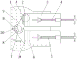
FIG. 1 is a schematic structural view of the present invention;
FIG. 2 is a schematic cross-sectional view at A of FIG. 1 according to the present invention;
FIG. 3 is a schematic structural diagram of a first supporting block according to the present invention;
FIG. 4 is a schematic cross-sectional view at B of FIG. 1 according to the present invention;
in the figure: 1. a support base; 2. a first support block; 3. a first clamp base; 4. a first limit screw; 5. a second limit screw; 6. a second clamp base; 7. fixing a column; 8. a rotating ring; 9. a first connecting plate; 10. a spring; 11. a first adjusting clamping groove; 12. connecting the sliding block; 13. a limiting block; 14. a limiting rod; 15. a guide chute; 16. a connecting slide hole; 17. a second adjusting clamping groove; 18. adjusting the screw rod; 19. a second support block; 20. and (5) scale marking.
Detailed Description
The technical solutions in the embodiments of the present invention will be clearly and completely described below with reference to the drawings in the embodiments of the present invention, and it is obvious that the described embodiments are only a part of the embodiments of the present invention, and not all of the embodiments. All other embodiments, which can be derived by a person skilled in the art from the embodiments given herein without making any creative effort, shall fall within the protection scope of the present invention.
Referring to fig. 1-4, the present invention provides a technical solution: a fixture tool for welding a switch cabinet comprises a supporting base 1, a fixed column 7 is arranged on the front surface of the supporting base 1, a rotating ring 8 is sleeved on the outer side of the fixed column 7, the position of a second fixture seat 6 is convenient to rotate and adjust, an adjusting screw 18 is connected to the inner side of the rotating ring 8 through a threaded portion, a second adjusting clamping groove 17 is formed in the outer surface of the fixed column 7, the adjusting screw 18 is in matched connection with the fixed column 7 through the second adjusting clamping groove 17, the rotating ring 8 is convenient to be connected and fixed with the fixed column 7, a second supporting block 19 is fixed to the outer surface of the rotating ring 8 through a second connecting plate, a second fixture seat 6 is welded to one side wall of the second supporting block 19, a second limiting screw 5 is arranged on the front surface of the second fixture seat 6, the plate to be welded is convenient to be clamped and fixed, a first connecting plate 9 is fixed to the upper end of the front, connecting slide hole 16 has been seted up to 2 inboard of first supporting block, be convenient for adjust the high position of first anchor clamps seat 3, connecting slide hole 16 inboard is provided with link block 12, link block 12 side fixed surface has first anchor clamps seat 3, 3 front surfaces of first anchor clamps seat are provided with first stop screw 4, be convenient for press from both sides tightly fixedly to treating the welding plate, another lateral wall of link block 12 is fixed with first anchor clamps seat 3, the mounting groove has been seted up to 3 inboard upper ends of first anchor clamps seat, the mounting groove inboard is provided with gag lever post 14, be convenient for restrict the slip between first anchor clamps seat 3 and the first supporting block 2, gag lever post 14 outside cover is equipped with spring 10, first adjusting clamping groove 11 has been seted up to 2 side surfaces of first supporting block, gag lever post 14 cooperates through first adjusting clamping groove 11 with first supporting block 2 and is connected, be convenient for make first anchor clamps seat 3 fix with first supporting block 2 fast.
Preferably, the front surface of the rotating ring 8 is provided with scale marks 20, and fifty scale marks 20 are uniformly distributed along the circumferential direction of the rotating ring 8, so that the rotating angle of the rotating ring 8 rotating around the fixing column 7 can be conveniently marked.
Preferably, the cross section of the second adjusting clamping grooves 17 is rectangular, and the number of the second adjusting clamping grooves 17 is equal to the number of the scale marks 20, so that the position of the rotating ring 8 can be adjusted better.
Preferably, a guide sliding groove 15 is formed in one side surface of the first supporting block 2, a protruding block is arranged on one side surface of the limiting block 13, the protruding block corresponds to the guide sliding groove 15, and the first fixture seat 3 can be moved along the height direction of the first supporting block 2 better.
Preferably, first regulation draw-in groove 11 is circular, and first regulation draw-in groove 11 is provided with a plurality ofly along the long limit equidistance of first supporting block 2, is convenient for better adjusting the position of first anchor clamps seat 3.
Preferably, the limiting rods 14 are provided with two limiting rods 14, the two limiting rods 14 are fixed through the handle plate, and the first clamp seat 3 and the first supporting block 2 are conveniently and better connected and fixed.
Preferably, the inner side of the supporting base 1 is provided with a through hole which penetrates through two side walls of the supporting base 1, so that dust and welding debris on the upper surface of the supporting base 1 can be discharged downwards better.
Preferably, first anchor clamps seat 3 is in the coplanar with second anchor clamps seat 6, and 6 one end of second anchor clamps seat is provided with the chamfer, when being convenient for reduce second anchor clamps seat 6 and rotate, causes the scratch to outside personnel.
A use method of a fixture tool for welding a switch cabinet comprises the following steps:
a. two plates to be welded are respectively placed on the first clamp seat 3 and the second clamp seat 6, then the plates to be welded are respectively clamped and fixed through the second limiting screw 5 and the first limiting screw 4, and at the moment, the rotary adjusting screw 18 can be rotationally conveyed to be separated from the inner side of the second adjusting clamping groove 17, so that the rotary ring 8 rotates around the fixed column 7;
b. the included angle between two plates to be welded can be observed through the scale marks 20, and the adjusting screw 18 is rotated and conveyed to enter the inner side of the other second adjusting clamping groove 17 after adjustment, so that the fixing column 7 and the rotating ring 8 can be fixed, and two plates to be welded which are positioned on the same plane and at different included angles can be conveniently welded;
c. the limiting rod 14 is pulled to move towards the side departing from the first adjusting clamping groove 11, so that the limiting rod 14 is separated from the inner side of the first adjusting clamping groove 11, and the spring 10 is elastically shortened;
d. the first fixture seat 3 and the first supporting block 2 slide through the connecting slide block 12 and the connecting slide hole 16, and the first fixture seat 3 can better slide along the height of the first supporting block 2 through the matching of the guide slide groove 15 and the convex block, so that the height of one of the plates to be welded is driven to be increased;
e. after the height position of one of the plates to be welded is adjusted, the limiting rod 14 is loosened, and the limiting rod 14 enters the inner side of the other first adjusting clamping groove 11 under the pushing of the elastic force of the spring 10, so that the first clamp seat 3 and the first supporting block 2 can be fixed, and two plates to be welded, which are positioned on the same plane and at different heights, can be welded conveniently.
In summary, the limiting rod, the connecting slide block, the first adjusting slot, the connecting slide hole and the limiting block are arranged, so that inconvenience in adjusting the positions of the two fixtures is avoided, when the two to-be-welded plates with different heights are fixed, the fixtures are required to be fixed with objects with different heights outside through bolts, the trouble and time are wasted, the operation efficiency is affected, the two to-be-welded plates with different heights are easily connected by the device, the practicability of the device is improved, the problem that the included angle positions of the two fixtures cannot be well adjusted due to the arrangement of the fixing column, the rotating ring, the adjusting screw rod and the second adjusting slot is avoided, the using effect is poor, the positions of the two fixtures are conveniently adjusted by the device, the two to-be-welded plates with different included angles are clamped and fixed, and the versatility of the device is improved.
Although embodiments of the present invention have been shown and described, it will be appreciated by those skilled in the art that changes, modifications, substitutions and alterations can be made in these embodiments without departing from the principles and spirit of the invention, the scope of which is defined in the appended claims and their equivalents.
Claims (9)
1. The utility model provides a fixture attachment for welding cubical switchboard, includes support base (1), its characterized in that: the front surface of the supporting base (1) is provided with a fixing column (7), the outer side of the fixing column (7) is sleeved with a rotating ring (8), the inner side of the rotating ring (8) is connected with an adjusting screw (18) through a threaded portion, the outer surface of the fixing column (7) is provided with a second adjusting clamping groove (17), the adjusting screw (18) and the fixing column (7) are in matched connection through the second adjusting clamping groove (17), the outer surface of the rotating ring (8) is fixedly provided with a second supporting block (19) through a second connecting plate, one side wall of the second supporting block (19) is welded with a second clamp seat (6), the front surface of the second clamp seat (6) is provided with a second limiting screw (5), the upper end of the front surface of the fixing column (7) is fixedly provided with a first connecting plate (9), and the other end of the first connecting plate (9) is fixedly, connection slide opening (16) have been seted up to first supporting block (2) inboard, connection slide opening (16) inboard is provided with link block (12), link block (12) a side fixed surface has first anchor clamps seat (3), first anchor clamps seat (3) front surface is provided with first stop screw (4), another lateral wall of link block (12) is fixed with first anchor clamps seat (3), the mounting groove has been seted up to first anchor clamps seat (3) inboard upper end, the mounting groove inboard is provided with gag lever post (14), gag lever post (14) outside cover is equipped with spring (10), first adjusting slot (11) have been seted up to first supporting block (2) a side surface, gag lever post (14) cooperate through first adjusting slot (11) with first supporting block (2) and are connected.
2. The fixture tool for welding the switch cabinet according to claim 1, wherein: the front surface of the rotating ring (8) is provided with scale marks (20), and fifty scale marks are uniformly distributed on the scale marks (20) along the circumferential direction of the rotating ring (8).
3. The fixture tool for welding the switch cabinet according to claim 2, wherein: the cross section of the second adjusting clamping groove (17) is rectangular, and the number of the second adjusting clamping grooves (17) is equal to that of the scale marks (20).
4. The fixture tool for welding the switch cabinet according to claim 1, wherein: a guide sliding groove (15) is formed in one side surface of the first supporting block (2), a protruding block is arranged on one side surface of the limiting block (13), and the protruding block corresponds to the guide sliding groove (15).
5. The fixture tool for welding the switch cabinet according to claim 1, wherein: first regulation draw-in groove (11) are circular, first regulation draw-in groove (11) are provided with a plurality ofly along first supporting block (2) long limit equidistance.
6. The fixture tool for welding the switch cabinet according to claim 1, wherein: the limiting rods (14) are arranged in two numbers, and the two limiting rods (14) are fixed through handle plates.
7. The fixture tool for welding the switch cabinet according to claim 1, wherein: the inner side of the supporting base (1) is provided with a through hole, and the through hole penetrates through two side walls of the supporting base (1).
8. The fixture tool for welding the switch cabinet according to claim 1, wherein: the first clamp seat (3) and the second clamp seat (6) are located on the same plane, and one end of the second clamp seat (6) is provided with a chamfer.
9. The use method of the fixture tool for welding the switch cabinet is characterized by comprising the following steps of: the method comprises the following steps:
a. two plates to be welded are respectively placed on the first clamp seat (3) and the second clamp seat (6), then the plates to be welded are clamped and fixed through the second limiting screw (5) and the first limiting screw (4), and at the moment, the adjusting screw (18) can be rotationally conveyed to be separated from the inner side of the second adjusting clamping groove (17), so that the rotating ring (8) rotates around the fixing column (7);
b. the included angle between two plates to be welded can be observed through the scale marks (20), and the adjusting screw (18) is rotationally conveyed to enter the inner side of the other second adjusting clamping groove (17) after adjustment, so that the fixed column (7) and the rotating ring (8) can be fixed, and two plates to be welded which are positioned on the same plane and at different included angles can be conveniently welded;
c. the limiting rod (14) is pulled to move towards the side departing from the first adjusting clamping groove (11), so that the limiting rod (14) is separated from the inner side of the first adjusting clamping groove (11), and the spring (10) is elastically shortened;
d. the first clamp seat (3) and the first supporting block (2) slide through the connecting slide block (12) and the connecting slide hole (16), and the first clamp seat (3) can better slide along the height of the first supporting block (2) through the matching of the guide slide groove (15) and the convex block, so that the height of one of the plates to be welded is driven to be increased;
e. after the height position of one of the plates to be welded is adjusted, the limiting rod (14) is loosened, the limiting rod (14) enters the inner side of the other first adjusting clamping groove (11) under the pushing of the elastic force of the spring (10), so that the first clamp seat (3) and the first supporting block (2) can be fixed, and two plates to be welded, which are positioned on the same plane and at different heights, can be welded conveniently.
Priority Applications (1)
| Application Number | Priority Date | Filing Date | Title |
|---|---|---|---|
| CN202110271478.8A CN113102932A (en) | 2021-03-12 | 2021-03-12 | Fixture tool for welding switch cabinet and using method thereof |
Applications Claiming Priority (1)
| Application Number | Priority Date | Filing Date | Title |
|---|---|---|---|
| CN202110271478.8A CN113102932A (en) | 2021-03-12 | 2021-03-12 | Fixture tool for welding switch cabinet and using method thereof |
Publications (1)
| Publication Number | Publication Date |
|---|---|
| CN113102932A true CN113102932A (en) | 2021-07-13 |
Family
ID=76711212
Family Applications (1)
| Application Number | Title | Priority Date | Filing Date |
|---|---|---|---|
| CN202110271478.8A Pending CN113102932A (en) | 2021-03-12 | 2021-03-12 | Fixture tool for welding switch cabinet and using method thereof |
Country Status (1)
| Country | Link |
|---|---|
| CN (1) | CN113102932A (en) |
Cited By (1)
| Publication number | Priority date | Publication date | Assignee | Title |
|---|---|---|---|---|
| CN113579618A (en) * | 2021-08-18 | 2021-11-02 | 江苏氧滋康电器有限公司 | Clamp for machining compressor end cover and using method thereof |
Citations (17)
| Publication number | Priority date | Publication date | Assignee | Title |
|---|---|---|---|---|
| CN207414675U (en) * | 2017-11-06 | 2018-05-29 | 南京机电职业技术学院 | A kind of reinforcement welding auxiliary device |
| CN108568635A (en) * | 2018-06-27 | 2018-09-25 | 湖北深成机械设备股份有限公司 | A kind of fixture based on weld car good antiskid effect |
| CN208117095U (en) * | 2018-01-27 | 2018-11-20 | 江苏伟硕机械有限公司 | A kind of automobile parts welding fixture |
| CN208468516U (en) * | 2017-12-25 | 2019-02-05 | 伯奈聚合材料盐城有限公司 | A kind of plastic material Special Fixture for Machining |
| WO2019095777A1 (en) * | 2017-11-20 | 2019-05-23 | 东莞理工学院 | Irregular pipe welding fixture |
| CN209394204U (en) * | 2018-11-16 | 2019-09-17 | 广州登峰机械设备有限公司 | A kind of auto welding jig |
| CN209598575U (en) * | 2019-03-18 | 2019-11-08 | 菏泽学院 | A kind of welding fixture tooling of angle adjustable |
| CN210210102U (en) * | 2019-05-31 | 2020-03-31 | 天津嘉诺达自动化设备有限公司 | Anchor clamps for machining convenient to adjust |
| CN210254918U (en) * | 2019-05-07 | 2020-04-07 | 天津一新管道设备有限公司 | Pipe fitting welding and fixing clamp |
| CN210334914U (en) * | 2019-06-08 | 2020-04-17 | 青岛谊东海洋石油工程有限公司 | Fixing equipment for welding |
| CN210616283U (en) * | 2019-08-20 | 2020-05-26 | 钟国龙 | Frock clamp for foundry goods |
| CN210790681U (en) * | 2019-10-09 | 2020-06-19 | 陕西烨晟机械制造有限公司 | Clamp for machining gearbox shell |
| CN211966454U (en) * | 2020-03-03 | 2020-11-20 | 苏州盟杨机电自动化有限公司 | Welding jig with quick change structure |
| CN212145126U (en) * | 2020-04-19 | 2020-12-15 | 刘宇 | Electronic component welding clamping device |
| CN212239813U (en) * | 2020-05-13 | 2020-12-29 | 王迪 | Metal welding clamping tool |
| CN212420305U (en) * | 2020-06-18 | 2021-01-29 | 无锡帝澳硬面材料有限公司 | Angle adjusting device for pipe fitting welding |
| CN212672562U (en) * | 2020-06-15 | 2021-03-09 | 山东华卫建设集团有限公司 | Concrete pump pipe support |
-
2021
- 2021-03-12 CN CN202110271478.8A patent/CN113102932A/en active Pending
Patent Citations (17)
| Publication number | Priority date | Publication date | Assignee | Title |
|---|---|---|---|---|
| CN207414675U (en) * | 2017-11-06 | 2018-05-29 | 南京机电职业技术学院 | A kind of reinforcement welding auxiliary device |
| WO2019095777A1 (en) * | 2017-11-20 | 2019-05-23 | 东莞理工学院 | Irregular pipe welding fixture |
| CN208468516U (en) * | 2017-12-25 | 2019-02-05 | 伯奈聚合材料盐城有限公司 | A kind of plastic material Special Fixture for Machining |
| CN208117095U (en) * | 2018-01-27 | 2018-11-20 | 江苏伟硕机械有限公司 | A kind of automobile parts welding fixture |
| CN108568635A (en) * | 2018-06-27 | 2018-09-25 | 湖北深成机械设备股份有限公司 | A kind of fixture based on weld car good antiskid effect |
| CN209394204U (en) * | 2018-11-16 | 2019-09-17 | 广州登峰机械设备有限公司 | A kind of auto welding jig |
| CN209598575U (en) * | 2019-03-18 | 2019-11-08 | 菏泽学院 | A kind of welding fixture tooling of angle adjustable |
| CN210254918U (en) * | 2019-05-07 | 2020-04-07 | 天津一新管道设备有限公司 | Pipe fitting welding and fixing clamp |
| CN210210102U (en) * | 2019-05-31 | 2020-03-31 | 天津嘉诺达自动化设备有限公司 | Anchor clamps for machining convenient to adjust |
| CN210334914U (en) * | 2019-06-08 | 2020-04-17 | 青岛谊东海洋石油工程有限公司 | Fixing equipment for welding |
| CN210616283U (en) * | 2019-08-20 | 2020-05-26 | 钟国龙 | Frock clamp for foundry goods |
| CN210790681U (en) * | 2019-10-09 | 2020-06-19 | 陕西烨晟机械制造有限公司 | Clamp for machining gearbox shell |
| CN211966454U (en) * | 2020-03-03 | 2020-11-20 | 苏州盟杨机电自动化有限公司 | Welding jig with quick change structure |
| CN212145126U (en) * | 2020-04-19 | 2020-12-15 | 刘宇 | Electronic component welding clamping device |
| CN212239813U (en) * | 2020-05-13 | 2020-12-29 | 王迪 | Metal welding clamping tool |
| CN212672562U (en) * | 2020-06-15 | 2021-03-09 | 山东华卫建设集团有限公司 | Concrete pump pipe support |
| CN212420305U (en) * | 2020-06-18 | 2021-01-29 | 无锡帝澳硬面材料有限公司 | Angle adjusting device for pipe fitting welding |
Cited By (1)
| Publication number | Priority date | Publication date | Assignee | Title |
|---|---|---|---|---|
| CN113579618A (en) * | 2021-08-18 | 2021-11-02 | 江苏氧滋康电器有限公司 | Clamp for machining compressor end cover and using method thereof |
Similar Documents
| Publication | Publication Date | Title |
|---|---|---|
| CN218311688U (en) | Angle steel cross arm welding frock | |
| CN211306247U (en) | Relay protection debugging table | |
| CN211530607U (en) | Wire clamping and fixing device for power equipment | |
| CN212341534U (en) | Fixing structure for power communication optical cable joint box | |
| CN211046147U (en) | Low-voltage distribution cabinet convenient to installation | |
| CN113263479A (en) | Electrified high-voltage joint bolt fastening device of transformer substation | |
| CN219617083U (en) | Blade repairing platform of wind generating set | |
| CN206060114U (en) | It is a kind of to be easy to fixed bus duct | |
| CN220325467U (en) | Motor winding softens frock | |
| CN223513027U (en) | Insulating pull rod test device | |
| CN112072531A (en) | Transformer substation disconnecting link static contact cleaning tool | |
| CN218252252U (en) | A positioning device for busbar bending machine | |
| CN210997558U (en) | Clamps that can clamp D-type busbars in switch cabinets of various specifications | |
| CN212626668U (en) | Supporting device of switch cabinet electrical automation equipment | |
| CN211439191U (en) | Bus waste assembly recovery processing device with high stability | |
| CN215732816U (en) | A low-voltage switchgear with stable connection structure | |
| CN215087319U (en) | Test bench for electrical engineering | |
| CN224217965U (en) | Electrical control cabinet convenient to maintain | |
| CN219477352U (en) | Switch cabinet with multistage protection | |
| CN215733089U (en) | Regulator cubicle connecting plate assembly fixture | |
| CN120184762B (en) | High-low voltage power cabinet for power engineering | |
| CN223960901U (en) | Clamping device capable of adapting to machining of shell sizes of different tank-type circuit breakers | |
| CN219946106U (en) | Bearing repair tool | |
| CN219025701U (en) | Portable busbar processing bender | |
| CN222235278U (en) | Converter controller convenient to installation |
Legal Events
| Date | Code | Title | Description |
|---|---|---|---|
| PB01 | Publication | ||
| PB01 | Publication | ||
| SE01 | Entry into force of request for substantive examination | ||
| SE01 | Entry into force of request for substantive examination | ||
| RJ01 | Rejection of invention patent application after publication | ||
| RJ01 | Rejection of invention patent application after publication |
Application publication date: 20210713 |