CN113101394A - Liquid disinfection equipment - Google Patents
Liquid disinfection equipment Download PDFInfo
- Publication number
- CN113101394A CN113101394A CN202110392212.9A CN202110392212A CN113101394A CN 113101394 A CN113101394 A CN 113101394A CN 202110392212 A CN202110392212 A CN 202110392212A CN 113101394 A CN113101394 A CN 113101394A
- Authority
- CN
- China
- Prior art keywords
- liquid
- seat
- belt pulley
- box
- disinfection
- Prior art date
- Legal status (The legal status is an assumption and is not a legal conclusion. Google has not performed a legal analysis and makes no representation as to the accuracy of the status listed.)
- Withdrawn
Links
Images


Classifications
-
- A—HUMAN NECESSITIES
- A61—MEDICAL OR VETERINARY SCIENCE; HYGIENE
- A61L—METHODS OR APPARATUS FOR STERILISING MATERIALS OR OBJECTS IN GENERAL; DISINFECTION, STERILISATION OR DEODORISATION OF AIR; CHEMICAL ASPECTS OF BANDAGES, DRESSINGS, ABSORBENT PADS OR SURGICAL ARTICLES; MATERIALS FOR BANDAGES, DRESSINGS, ABSORBENT PADS OR SURGICAL ARTICLES
- A61L2/00—Methods or apparatus for disinfecting or sterilising materials or objects other than foodstuffs or contact lenses; Accessories therefor
- A61L2/16—Methods or apparatus for disinfecting or sterilising materials or objects other than foodstuffs or contact lenses; Accessories therefor using chemical substances
- A61L2/18—Liquid substances or solutions comprising solids or dissolved gases
-
- A—HUMAN NECESSITIES
- A61—MEDICAL OR VETERINARY SCIENCE; HYGIENE
- A61L—METHODS OR APPARATUS FOR STERILISING MATERIALS OR OBJECTS IN GENERAL; DISINFECTION, STERILISATION OR DEODORISATION OF AIR; CHEMICAL ASPECTS OF BANDAGES, DRESSINGS, ABSORBENT PADS OR SURGICAL ARTICLES; MATERIALS FOR BANDAGES, DRESSINGS, ABSORBENT PADS OR SURGICAL ARTICLES
- A61L2/00—Methods or apparatus for disinfecting or sterilising materials or objects other than foodstuffs or contact lenses; Accessories therefor
- A61L2/26—Accessories or devices or components used for biocidal treatment
-
- C—CHEMISTRY; METALLURGY
- C02—TREATMENT OF WATER, WASTE WATER, SEWAGE, OR SLUDGE
- C02F—TREATMENT OF WATER, WASTE WATER, SEWAGE, OR SLUDGE
- C02F1/00—Treatment of water, waste water, or sewage
- C02F1/50—Treatment of water, waste water, or sewage by addition or application of a germicide or by oligodynamic treatment
Abstract
The invention relates to a disinfection device, in particular to a liquid disinfection device which comprises a disinfection executing mechanism and an antirust shell mechanism, wherein the disinfection executing mechanism and the antirust shell mechanism can be used for carrying out double-pressure disinfection liquid adding, the device can save power, the device can reduce power consumption by utilizing liquid power, the device can complete the mixing of disinfection liquid and liquid in the process of accelerating the liquid, and the disinfection executing mechanism is connected with the antirust shell mechanism.
Description
Technical Field
The invention relates to a disinfection device, in particular to a liquid disinfection device.
Background
In the liquid disinfection process, the traditional disinfection mode mostly adopts a stirring disinfection mode to mix the disinfectant and the liquid to be disinfected, so that the flow rate of the liquid can be reduced, and additional stirring equipment needs to be equipped, so that the liquid disinfection equipment is designed.
Disclosure of Invention
The invention mainly solves the technical problem of providing liquid disinfection equipment, wherein the equipment can perform double-pressure disinfection liquid adding, the equipment can save power, the equipment can reduce power consumption by utilizing liquid power, and the equipment can complete the mixing of the disinfection liquid and the liquid in the process of accelerating the liquid.
In order to solve the technical problems, the invention relates to a disinfection device, and particularly relates to a liquid disinfection device which comprises a disinfection executing mechanism and an antirust shell mechanism, wherein the device can perform double-pressure disinfection, the device can save power, the device can reduce power consumption by utilizing liquid power, and the device can complete the mixing of disinfection liquid and liquid in the process of accelerating the liquid.
The disinfection executing mechanism is connected with the rust-proof shell mechanism.
As a further optimization of the technical scheme, the disinfection execution mechanism of the liquid disinfection equipment comprises a disinfectant inlet pipe, a disinfected liquid inlet pipe, a supporting leg transfer box, a square hole, a push-pull seat, an output pipe, a mixing box, a mixing output pipe, a bearing seat, a bevel gear I, a rotating shaft, a bearing seat I, a hinged arm, a hinged seat, a fixed support, a square column, a spring, a belt pulley, a shaft-provided cam, a belt pulley I, a matching seat, a belt I, a motor belt pulley, a motor, a belt pulley II, a shaft-provided impeller, a liquid outlet one-way valve, a liquid inlet one-way valve, a square hole I, a piston, a spring I, a pull cavity and a pressure cavity, wherein the disinfectant inlet pipe is connected with the supporting leg transfer box, the disinfected liquid inlet pipe is connected and communicated with the mixing box, the two sides of the supporting leg transfer box are symmetrically provided with the square holes, the push-pull seat is, the output pipe is connected and communicated with a mixing box, the mixing box is connected and communicated with the mixed output pipe, the mixing box is connected with a bearing seat, a bevel gear is meshed with the bevel gear I, the bevel gear I is connected with a rotating shaft, the rotating shaft is rotationally connected with the bearing seat I, the bearing seat I is connected with a transfer box with supporting legs, a push-pull seat is hinged with a hinged arm, the hinged arm is hinged with a hinged seat, a fixed support is connected with the transfer box with supporting legs, a square column is slidably connected with a square hole I arranged on the fixed support, the square column is connected with the hinged seat, a spring is sleeved on the square column, two ends of the spring are respectively connected on the fixed support and a matching seat, the matching seat is connected with the square column, a belt is in friction connection with the belt pulley, the belt pulley is connected with a cam with a belt shaft, the cam with the fixed support is rotationally connected with the fixed support, the, belt I and motor pulley friction connection, motor pulley links to each other with the motor, the motor links to each other with taking the landing leg transfer case, belt pulley II and belt friction connection, belt pulley II links to each other with the pivot, the tape spool impeller rotates with the mixing box to be connected, the tape spool impeller links to each other with bevel gear, it all sets up in the pressure chamber to go out liquid check valve and feed liquor check valve, the pressure chamber sets up in taking the landing leg transfer case, piston and pull chamber sliding connection, spring I cover is on the push-and-pull seat, the push-and-pull seat links to each other with the piston, spring I both ends are connected respectively on taking landing leg transfer case and piston, the pull chamber sets up in taking the landing leg transfer case, the pull chamber is linked together with the pressure chamber, disinfectant admission pipe is linked.
As a further optimization of the technical scheme, the antirust shell mechanism of the liquid disinfection equipment comprises a box cover, a box body, an opening I, a reinforcing seat and an opening II, wherein the box cover is fixed on the box body through a screw, the box body is provided with the opening and the opening I, the reinforcing seat is connected with the box body, the opening II is formed in the box body, a disinfectant inlet pipe and a disinfected liquid inlet pipe are both connected with the reinforcing seat, a transfer box with supporting legs is connected with the box body, the disinfectant inlet pipe penetrates through the opening, the disinfected liquid inlet pipe penetrates through the opening I, a mixing output pipe penetrates through the opening II, and the mixing box is connected with the box body.
As a further optimization of the technical scheme, the number of the push-pull seats of the liquid disinfection equipment is two.
The liquid disinfection equipment has the beneficial effects that:
according to the liquid disinfection equipment, double-pressure disinfection liquid can be added, power can be saved, the equipment can reduce power consumption by utilizing liquid power, and the equipment can complete mixing of the disinfection liquid and the liquid in the process of accelerating the liquid.
Drawings
The invention is described in further detail below with reference to the accompanying drawings and specific embodiments.
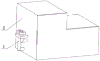
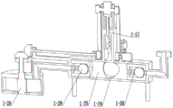
FIG. 1 is a first schematic view of a liquid disinfection apparatus according to the present invention.
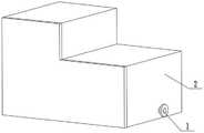
FIG. 2 is a schematic structural diagram of a liquid disinfection apparatus according to the present invention.
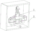
Fig. 3 is a schematic structural diagram three of a liquid disinfection device of the present invention.
Fig. 4 is a fourth schematic structural view of a liquid disinfection apparatus according to the present invention.
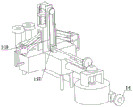
Fig. 5 is a first schematic structural diagram of a disinfection actuator 1 of a liquid disinfection device according to the present invention.
Fig. 6 is a second schematic structural diagram of a disinfection actuator 1 of a liquid disinfection device according to the present invention.
Fig. 7 is a schematic structural diagram three of a disinfection actuator 1 of a liquid disinfection device according to the invention.
Fig. 8 is a fourth schematic structural diagram of a disinfection actuator 1 of a liquid disinfection device according to the invention.
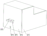
Fig. 9 is a first structural schematic diagram of the rust-proof housing mechanism 2 of the liquid disinfection apparatus of the present invention.
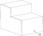
Fig. 10 is a structural schematic diagram of a rust-proof housing mechanism 2 of the liquid disinfection apparatus of the present invention.
In the figure: a disinfection actuator 1; a disinfectant inlet pipe 1-1; the liquid to be disinfected enters the pipe 1-2; a transfer case 1-3 with support legs; 1-4 of square holes; 1-5 of a push-pull seat; an output pipe 1-6; 1-7 of a mixing box; 1-8 parts of a mixing output pipe; 1-9 of a bearing seat; 1-10 parts of bevel gears; bevel gear I1-11; 1-12 of a rotating shaft; bearing seats I1-13; articulated arms 1-14; hinge seats 1-15; 1-16 of a fixed support; 1-17 of square column; springs 1-18; belts 1-19; 1-20 parts of belt pulley; cam with shaft 1-21; pulley I1-22; 1-23 of a matching seat; belts I1-24; 1-25 of a motor belt pulley; motors 1-26; pulley II 1-27; 1-28 of a shaft impeller; liquid outlet one-way valve 1-29; 1-30 parts of liquid inlet one-way valve; square holes I1-31; pistons 1-32; springs I1-33; drawing cavities 1-34; pressure chambers 1-35; an antirust shell mechanism 2; a box cover 2-1; a box body 2-2; 2-3 of opening; opening I2-4; 2-5 of a reinforcing seat; opening II 2-6.
Detailed Description
The first embodiment is as follows:
the embodiment is described below with reference to fig. 1, fig. 2, fig. 3, fig. 4, fig. 5, fig. 6, fig. 7, fig. 8, fig. 9, and fig. 10, and the present invention relates to a disinfection apparatus, and more specifically, to a liquid disinfection apparatus, which includes a disinfection actuator 1 and an anti-rust housing mechanism 2, and is capable of performing double-pressure disinfection, so that the apparatus is capable of saving power, reducing power consumption by using hydrodynamic force, and mixing disinfection liquid and liquid in a process of accelerating liquid.
The disinfection actuating mechanism 1 is connected with the antirust shell mechanism 2.
The second embodiment is as follows:
the embodiment is described below with reference to fig. 1, fig. 2, fig. 3, fig. 4, fig. 5, fig. 6, fig. 7, fig. 8, fig. 9 and fig. 10, and the embodiment is further described, wherein the disinfection actuator 1 comprises a disinfectant inlet pipe 1-1, a disinfected liquid inlet pipe 1-2, a middle rotating box with legs 1-3, square holes 1-4, push-pull seats 1-5, an output pipe 1-6, a mixing box 1-7, a mixing output pipe 1-8, bearing seats 1-9, bevel gears 1-10, bevel gears I1-11, rotating shafts 1-12, bearing seats I1-13, hinged arms 1-14, hinged seats 1-15, fixed supports 1-16, square columns 1-17, springs 1-18, belts 1-19, belt pulleys 1-20, 1-21 parts of cam with shaft, 1-23 parts of belt pulley I1-22 parts of matching seat, 1-23 parts of belt I1-24 parts of motor belt pulley, 1-25 parts of motor, 1-26 parts of motor, II1-27 parts of belt pulley, 1-28 parts of impeller with shaft, 1-29 parts of liquid outlet one-way valve, 1-30 parts of liquid inlet one-way valve, 1-31 parts of square hole I1-31 parts of piston, 1-32 parts of spring I1-33 parts of drawing cavity, 1-34 parts of pressure cavity, 1-35 parts of pressure cavity, 1-1 parts of disinfectant inlet pipe and 1-3 parts of transfer box with supporting leg, 1-2 parts of inlet pipe for the disinfected liquid and 1-7 parts of mixing box are connected, 1-4 parts of square hole are symmetrically arranged on two sides of transfer box with supporting leg 1-3, 1-5 parts of drawing seat are connected with 1-4 parts of square hole, the output pipe 1-6 is connected and communicated with the mixing box 1-7, the mixing box 1-7 is connected and communicated with the mixing output pipe 1-8, the mixing box 1-7 is connected and communicated with a bearing seat 1-9, a bevel gear 1-10 is meshed with a bevel gear I1-11, a bevel gear I1-11 is connected with a rotating shaft 1-12, the rotating shaft 1-12 is rotatably connected with a bearing seat I1-13, the bearing seat I1-13 is connected with a transfer box 1-3 with supporting legs, a push-pull seat 1-5 is hinged with a hinged arm 1-14, the hinged arm 1-14 is hinged with a hinged seat 1-15, a fixed support 1-16 is connected with the transfer box 1-3 with supporting legs, a square column 1-17 is slidably connected with a square hole I1-31 arranged on the fixed support 1-16, the square column 1-17 is connected with the hinged seat 1-15, the springs 1-18 are sleeved on the square columns 1-17, two ends of the springs 1-18 are respectively connected with the fixed supports 1-16 and the matching seats 1-23, the matching seats 1-23 are connected with the square columns 1-17, the belts 1-19 are in friction connection with the belt pulleys 1-20, the belt pulleys 1-20 are connected with the cam with a shaft 1-21, the cam with a shaft 1-21 is in rotation connection with the fixed supports 1-16, the cam with a shaft 1-21 is connected with the belt pulleys I1-22, the cam with a shaft 1-21 is in contact with the matching seats 1-23, the belt pulleys I1-22 are in friction connection with the belts I1-24, the belts I1-24 are in friction connection with the motor belt pulleys 1-25, the motor belt pulleys 1-25 are connected with the motors 1-26, the motors 1-26 are connected with the middle rotating boxes with the supporting legs 1, the belt pulley II1-27 is frictionally connected with a belt 1-19, the belt pulley II1-27 is connected with a rotating shaft 1-12, a belt shaft impeller 1-28 is rotationally connected with a mixing box 1-7, the belt shaft impeller 1-28 is connected with a bevel gear 1-10, a liquid outlet one-way valve 1-29 and a liquid inlet one-way valve 1-30 are arranged in a pressure chamber 1-35, the pressure chamber 1-35 is arranged in a middle rotating box 1-3 with supporting legs, a piston 1-32 is slidably connected with a drawing chamber 1-34, a spring I1-33 is sleeved on a drawing seat 1-5, the drawing seat 1-5 is connected with the piston 1-32, two ends of the spring I1-33 are respectively connected with the middle rotating box 1-3 with supporting legs and the piston 1-32, the drawing chamber 1-34 is arranged in the middle rotating box 1-3 with supporting legs, the drawing cavity 1-34 is communicated with a pressure cavity 1-35, a disinfectant inlet pipe 1-1 is communicated with the pressure cavity 1-35, an output pipe 1-6 is communicated with the pressure cavity 1-35, the disinfectant inlet pipe 1-1 is externally connected with a pipeline capable of continuously disinfecting liquid, a disinfected liquid inlet pipe 1-2 is externally connected with a pipeline of liquid to be disinfected, a mixed output pipe 1-8 is externally connected with a receiving container or a pipeline, a motor 1-26 operates to drive a motor belt pulley 1-25 to rotate, the motor belt pulley 1-25 drives a belt pulley I1-22 to rotate through a belt I1-24 so as to drive a cam with a shaft 1-21 to rotate, the cam with the shaft 1-21 drives a matching seat 1-23 to reciprocate up and down through matching with a spring 1-18, and the matching seat 1-23 drives a hinge seat 1-15 to reciprocate up and down through a square column 1-17 The hinged seats 1-15 can drive the push-pull seats 1-5 to reciprocate through the hinged arms 1-14, the push-pull seats 1-5 can drive the pistons 1-32 to reciprocate through the cooperation of the springs I1-33, the pistons 1-32 can move away from and approach to each other in the reciprocating motion, when the pistons approach to each other, the formed pressure is double, and the superposed pressure and the superposed attraction force are formed under the condition that the driving thread of the cam with the shaft 1-21 is not changed, so that the disinfectant in the disinfectant pipeline externally connected with the disinfectant inlet pipe 1-1 can be better sucked into the pressure cavity 1-35 through the liquid inlet one-way valve 1-30, and then the liquid outlet one-way valve 1-29 is pressurized and flushed to enter the mixing box 1-7; the equipment can save power, the equipment can reduce power consumption by utilizing liquid power, the liquid to be disinfected in the external pipeline of the disinfected liquid inlet pipe 1-2 can continuously flow into the mixing box 1-7 from the disinfected liquid inlet pipe 1-2 to impact the belt shaft impeller 1-28, the belt shaft cam 1-21 can be driven to rotate the belt pulley 1-20, the belt pulley 1-20 can be driven to rotate the belt pulley II1-27 through the belt 1-19, the belt pulley II1-27 can be driven to rotate the bevel gear I1-11 through the rotating shaft 1-12, the bevel gear I1-11 can be driven to rotate the bevel gear 1-10, the bevel gear 1-10 can be driven to rotate the belt shaft impeller 1-28, the rotating direction of the belt shaft impeller 1-28 is clockwise seen from top to bottom, and the liquid to be disinfected which flows into the mixing box 1-7 from the disinfected liquid inlet pipe 1-2 can be driven to be disinfected The power-assisted function is realized on the rotation of the impeller 1-28 with the shaft, so that the driving force required by the rotation of the impeller 1-28 with the shaft is reduced, the power consumption is reduced, and the power is saved; the device can complete mixing of disinfectant and liquid in the process of accelerating the liquid, disinfectant intermittently falling from the output pipe 1-6 can fall into two adjacent blades of the impeller 1-28 with the shaft, when the disinfectant in the two adjacent blades rotates to the position where the liquid in the disinfected liquid inlet pipe 1-2 enters the mixing box 1-7, the disinfectant can be instantly flushed into the adjacent blades to be mixed with the disinfectant, the mixed liquid is accelerated along with the rotation of the impeller 1-28 with the shaft, and then the mixed liquid is thrown out from the mixing output pipe 1-8, so that the mixing is completed in the accelerating process.
The third concrete implementation mode:
the embodiment is described below with reference to fig. 1, fig. 2, fig. 3, fig. 4, fig. 5, fig. 6, fig. 7, fig. 8, fig. 9, fig. 10, and the embodiment is further described, where the rustproof case mechanism 2 includes a case cover 2-1, a case body 2-2, an opening 2-3, an opening I2-4, a reinforcement base 2-5, and an opening II2-6, the case cover 2-1 is fixed on the case body 2-2 by screws, the case body 2-2 is provided with the opening 2-3 and the opening I2-4, the reinforcement base 2-5 is connected to the case body 2-2, the opening II2-6 is provided on the case body 2-2, both the disinfectant inlet pipe 1-1 and the inlet pipe 1-2 for the liquid to be disinfected are connected to the reinforcement base 2-5, the middle rotating case 1-3 with legs is connected to the case body 2-2, the disinfectant inlet pipe 1-1 penetrates through the opening 2-3, the disinfected liquid inlet pipe 1-2 penetrates through the opening I2-4, the mixing output pipe 1-8 penetrates through the opening II2-6, and the mixing box 1-7 is connected with the box body 2-2.
The fourth concrete implementation mode:
the present embodiment will be described below with reference to fig. 1, 2, 3, 4, 5, 6, 7, 8, 9, and 10, and the present embodiment further describes the first embodiment in which the number of the push-pull bases 1 to 5 is two.
The working principle of the device is as follows: the equipment can perform double-pressure disinfectant adding, a disinfectant inlet pipe 1-1 is externally connected with a pipeline capable of continuously disinfecting liquid, a disinfected liquid inlet pipe 1-2 is externally connected with a pipeline of liquid to be disinfected, a mixed output pipe 1-8 is externally connected with a receiving container or a pipeline, a motor 1-26 operates to drive a motor belt pulley 1-25 to rotate, the motor belt pulley 1-25 drives a belt pulley I1-22 to rotate through a belt I1-24 and then drives a belt shaft cam 1-21 to rotate, the belt shaft cam 1-21 drives a matching seat 1-23 to reciprocate up and down through the matching of a spring 1-18, the matching seat 1-23 drives a hinged seat 1-15 to reciprocate up and down through a square column 1-17, the hinged seat 1-15 drives a push-pull seat 1-5 to reciprocate through a hinged arm 1-14, the push-pull seat 1-5 can drive the pistons 1-32 to reciprocate through the cooperation of the springs I1-33, the pistons 1-32 can be far away from and close to each other in the reciprocating motion due to the fact that the pistons on the two sides are close to each other, and when the pistons are close to each other, the formed pressure is double, and the superposed pressure and the superposed attraction force are formed under the condition that the driving thread of the cam with the shaft 1-21 is not changed, so that disinfectant in the disinfectant inlet pipe 1-1, which is externally connected with a disinfectant pipeline, can be better sucked into the pressure cavity 1-35 through the liquid inlet one-way valve 1-30, and then the liquid outlet one-way valve 1-29 is pressurized and flushed to enter the; the equipment can save power, the equipment can reduce power consumption by utilizing liquid power, the liquid to be disinfected in the external pipeline of the disinfected liquid inlet pipe 1-2 can continuously flow into the mixing box 1-7 from the disinfected liquid inlet pipe 1-2 to impact the belt shaft impeller 1-28, the belt shaft cam 1-21 can be driven to rotate the belt pulley 1-20, the belt pulley 1-20 can be driven to rotate the belt pulley II1-27 through the belt 1-19, the belt pulley II1-27 can be driven to rotate the bevel gear I1-11 through the rotating shaft 1-12, the bevel gear I1-11 can be driven to rotate the bevel gear 1-10, the bevel gear 1-10 can be driven to rotate the belt shaft impeller 1-28, the rotating direction of the belt shaft impeller 1-28 is clockwise seen from top to bottom, and the liquid to be disinfected which flows into the mixing box 1-7 from the disinfected liquid inlet pipe 1-2 can be driven to be disinfected The power-assisted function is realized on the rotation of the impeller 1-28 with the shaft, so that the driving force required by the rotation of the impeller 1-28 with the shaft is reduced, the power consumption is reduced, and the power is saved; the device can complete mixing of disinfectant and liquid in the process of accelerating the liquid, disinfectant intermittently falling from the output pipe 1-6 can fall into two adjacent blades of the impeller 1-28 with the shaft, when the disinfectant in the two adjacent blades rotates to the position where the liquid in the disinfected liquid inlet pipe 1-2 enters the mixing box 1-7, the disinfectant can be instantly flushed into the adjacent blades to be mixed with the disinfectant, the mixed liquid is accelerated along with the rotation of the impeller 1-28 with the shaft, and then the mixed liquid is thrown out from the mixing output pipe 1-8, so that the mixing is completed in the accelerating process.
It is to be understood that the above description is not intended to limit the present invention, and the present invention is not limited to the above examples, and that various changes, modifications, additions and substitutions which are within the spirit and scope of the present invention and which may be made by those skilled in the art are also within the scope of the present invention.
Claims (4)
1. The utility model provides a liquid disinfection equipment, includes disinfection actuating mechanism (1), rust-resistant shell mechanism (2), its characterized in that: the disinfection executing mechanism (1) is connected with the antirust shell mechanism (2).
2. A liquid disinfection apparatus as claimed in claim 1, wherein: the disinfection executing mechanism (1) comprises a disinfectant inlet pipe (1-1), a disinfected liquid inlet pipe (1-2), a transfer case (1-3) with supporting legs, square holes (1-4), a push-pull seat (1-5), an output pipe (1-6), a mixing case (1-7), a mixing output pipe (1-8), bearing seats (1-9), bevel gears (1-10), bevel gears I (1-11), rotating shafts (1-12), bearing seats I (1-13), articulated arms (1-14), articulated seats (1-15), fixed supports (1-16), square columns (1-17), springs (1-18), belts (1-19), belt pulleys (1-20), cam with shafts (1-21), A belt pulley I (1-22), a matching seat (1-23), a belt I (1-24), a motor belt pulley (1-25), a motor (1-26), a belt pulley II (1-27), a belt shaft impeller (1-28), a liquid outlet one-way valve (1-29), a liquid inlet one-way valve (1-30), a square hole I (1-31), a piston (1-32), a spring I (1-33), a drawing cavity (1-34) and a pressure cavity (1-35), a disinfectant inlet pipe (1-1) is connected with a supporting leg transfer box (1-3), a sterilized liquid inlet pipe (1-2) is connected and communicated with a mixing box (1-7), square holes (1-4) are symmetrically arranged on two sides of the supporting leg transfer box (1-3), a push-pull seat (1-5) is connected with the square holes (1-4) in a sliding way, the output pipe (1-6) is connected with the transfer case (1-3) with the supporting legs, the output pipe (1-6) is connected and communicated with the mixing case (1-7), the mixing case (1-7) is connected and communicated with the mixing output pipe (1-8), the mixing case (1-7) is connected with the bearing seat (1-9), the bevel gear (1-10) is meshed with the bevel gear I (1-11), the bevel gear I (1-11) is connected with the rotating shaft (1-12), the rotating shaft (1-12) is rotationally connected with the bearing seat I (1-13), the bearing seat I (1-13) is connected with the transfer case (1-3) with the supporting legs, the push-pull seat (1-5) is hinged with the hinged arm (1-14), the hinged arm (1-14) is hinged with the hinged seat (1-15), the fixed support (1-16) is connected with the transfer box (1-3) with the supporting legs, the square column (1-17) is connected with the square hole I (1-31) arranged on the fixed support (1-16) in a sliding way, the square column (1-17) is connected with the hinged seat (1-15), the spring (1-18) is sleeved on the square column (1-17), two ends of the spring (1-18) are respectively connected with the fixed support (1-16) and the matching seat (1-23), the matching seat (1-23) is connected with the square column (1-17), the belt (1-19) is connected with the belt pulley (1-20) in a friction way, the belt pulley (1-20) is connected with the cam (1-21) with the shaft, the cam (1-21) with the fixed support (1-16) is connected in a rotating way, the cam (1-21) with the shaft is connected with the belt pulley I (1-22), the cam (1-21) with a shaft is contacted with the matching seat (1-23), the belt pulley I (1-22) is connected with the belt I (1-24) in a friction way, the belt I (1-24) is connected with the motor belt pulley (1-25) in a friction way, the motor belt pulley (1-25) is connected with the motor (1-26), the motor (1-26) is connected with the supporting leg middle rotating box (1-3), the belt pulley II (1-27) is connected with the belt (1-19) in a friction way, the belt pulley II (1-27) is connected with the rotating shaft (1-12), the impeller (1-28) with the shaft is connected with the mixing box (1-7) in a rotation way, the impeller (1-28) with the shaft is connected with the bevel gear (1-10), the liquid outlet one-way valve (1-29) and the liquid inlet one-way valve (1-30) are both arranged in the pressure cavity (1-, the pressure chamber (1-35) is arranged in the transfer case with supporting legs (1-3), the piston (1-32) is connected with the drawing chamber (1-34) in a sliding way, the spring I (1-33) is sleeved on the drawing seat (1-5), the drawing seat (1-5) is connected with the piston (1-32), two ends of the spring I (1-33) are respectively connected with the transfer case with supporting legs (1-3) and the piston (1-32), the drawing chamber (1-34) is arranged in the transfer case with supporting legs (1-3), the drawing chamber (1-34) is communicated with the pressure chamber (1-35), the disinfectant inlet pipe (1-1) is communicated with the pressure chamber (1-35), and the output pipe (1-6) is communicated with the pressure chamber (1-35).
3. A liquid disinfection apparatus as claimed in claim 1, wherein: the anti-rust shell mechanism (2) comprises a box cover (2-1), a box body (2-2), an opening (2-3), an opening I (2-4), a reinforcing seat (2-5) and an opening II (2-6), the box cover (2-1) is fixed on the box body (2-2) through screws, the box body (2-2) is provided with the opening (2-3) and the opening I (2-4), the reinforcing seat (2-5) is connected with the box body (2-2), the opening II (2-6) is arranged on the box body (2-2), a disinfectant inlet pipe (1-1) and a disinfected liquid inlet pipe (1-2) are both connected with the reinforcing seat (2-5), the transfer box (1-3) with supporting legs is connected with the box body (2-2), and the disinfectant inlet pipe (1-1) penetrates through the opening (2-3), the sterilized liquid inlet pipe (1-2) penetrates through the opening I (2-4), the mixing output pipe (1-8) penetrates through the opening II (2-6), and the mixing box (1-7) is connected with the box body (2-2).
4. A liquid disinfection apparatus as claimed in claim 2, wherein: the number of the push-pull seats (1-5) is two.
Priority Applications (1)
| Application Number | Priority Date | Filing Date | Title |
|---|---|---|---|
| CN202110392212.9A CN113101394A (en) | 2021-04-13 | 2021-04-13 | Liquid disinfection equipment |
Applications Claiming Priority (1)
| Application Number | Priority Date | Filing Date | Title |
|---|---|---|---|
| CN202110392212.9A CN113101394A (en) | 2021-04-13 | 2021-04-13 | Liquid disinfection equipment |
Publications (1)
| Publication Number | Publication Date |
|---|---|
| CN113101394A true CN113101394A (en) | 2021-07-13 |
Family
ID=76716305
Family Applications (1)
| Application Number | Title | Priority Date | Filing Date |
|---|---|---|---|
| CN202110392212.9A Withdrawn CN113101394A (en) | 2021-04-13 | 2021-04-13 | Liquid disinfection equipment |
Country Status (1)
| Country | Link |
|---|---|
| CN (1) | CN113101394A (en) |
Cited By (1)
| Publication number | Priority date | Publication date | Assignee | Title |
|---|---|---|---|---|
| CN113713159A (en) * | 2021-09-22 | 2021-11-30 | 付耀平 | Air of hospital removes disinfection treatment facility |
Citations (19)
| Publication number | Priority date | Publication date | Assignee | Title |
|---|---|---|---|---|
| US5236600A (en) * | 1991-06-05 | 1993-08-17 | Hutchins Danny T | Process for controlling bacteria growth in water supply systems |
| US6177018B1 (en) * | 1996-09-27 | 2001-01-23 | Alpro-Dental Produkte Gmbh | Dosing mechanism to feed germicide or disinfectant into a water supplied supply device and the use thereof |
| JP2001145887A (en) * | 1999-11-22 | 2001-05-29 | Isomura:Kk | Disinfecting and sterilizing agent diluting water making apparatus |
| DE20304952U1 (en) * | 2003-03-25 | 2003-07-17 | M & M Ges Fuer Biotechnische A | Mobile appliance to disinfect water at open-air events comprises a water flow pipe with a flow meter, to control dosing pump to add disinfectant according to the water flow |
| EP1504767A1 (en) * | 2002-05-10 | 2005-02-09 | Family-Life Co., Ltd. | Apparatus for producing sterilized water |
| US20050084414A1 (en) * | 2003-10-17 | 2005-04-21 | Treiman Michael T. | Chemical proportioning and dispensing systems |
| CN201453699U (en) * | 2009-06-29 | 2010-05-12 | 北京英澳科技有限公司 | Unpowered sterilizer |
| CN103669489A (en) * | 2013-05-09 | 2014-03-26 | 上海沥源流体科技有限公司 | Water quality controller of water tank |
| CN105152286A (en) * | 2015-09-07 | 2015-12-16 | 太仓文广汇清洁设备有限公司 | Well water pipeline disinfectant addition system |
| CN106806953A (en) * | 2017-03-14 | 2017-06-09 | 中国医科大学附属盛京医院 | A kind of external ventricle drainage automatic speed-measuring and autompulse cleaning device |
| CN107585840A (en) * | 2017-10-17 | 2018-01-16 | 赣州汇桔科技有限公司 | A kind of sewage treatment unit |
| CN208762211U (en) * | 2018-06-14 | 2019-04-19 | 贵州水投水务集团锦屏有限公司 | A kind of control amount formula disinfection of tap water pipeline |
| CN110143652A (en) * | 2019-05-05 | 2019-08-20 | 广西柳钢环保股份有限公司 | Water control type industrial circulating water adding method thereof and medicine system |
| CN111039337A (en) * | 2018-10-12 | 2020-04-21 | 天津市石艺园林艺术工程有限公司 | Medicament direct-injection device for liquid pressure pipeline |
| CN111892136A (en) * | 2020-07-14 | 2020-11-06 | 深圳市万城科技有限公司 | Sewage treatment device with good disinfection effect |
| CN212050680U (en) * | 2020-04-18 | 2020-12-01 | 沧州聚隆化工有限公司 | Circulating water bactericide feeding device |
| CN212236964U (en) * | 2020-03-23 | 2020-12-29 | 中国人民解放军陆军军医大学第二附属医院 | Disinfectant preparation equipment for disinfection supply room |
| CN112191079A (en) * | 2020-09-27 | 2021-01-08 | 瑞安市凯宇环保设备有限公司 | Phthalic anhydride production tail gas environmental protection and energy saving processing apparatus |
| CN112390421A (en) * | 2020-11-17 | 2021-02-23 | 周远琴 | Tap water auxiliary sterilizing equipment |
-
2021
- 2021-04-13 CN CN202110392212.9A patent/CN113101394A/en not_active Withdrawn
Patent Citations (19)
| Publication number | Priority date | Publication date | Assignee | Title |
|---|---|---|---|---|
| US5236600A (en) * | 1991-06-05 | 1993-08-17 | Hutchins Danny T | Process for controlling bacteria growth in water supply systems |
| US6177018B1 (en) * | 1996-09-27 | 2001-01-23 | Alpro-Dental Produkte Gmbh | Dosing mechanism to feed germicide or disinfectant into a water supplied supply device and the use thereof |
| JP2001145887A (en) * | 1999-11-22 | 2001-05-29 | Isomura:Kk | Disinfecting and sterilizing agent diluting water making apparatus |
| EP1504767A1 (en) * | 2002-05-10 | 2005-02-09 | Family-Life Co., Ltd. | Apparatus for producing sterilized water |
| DE20304952U1 (en) * | 2003-03-25 | 2003-07-17 | M & M Ges Fuer Biotechnische A | Mobile appliance to disinfect water at open-air events comprises a water flow pipe with a flow meter, to control dosing pump to add disinfectant according to the water flow |
| US20050084414A1 (en) * | 2003-10-17 | 2005-04-21 | Treiman Michael T. | Chemical proportioning and dispensing systems |
| CN201453699U (en) * | 2009-06-29 | 2010-05-12 | 北京英澳科技有限公司 | Unpowered sterilizer |
| CN103669489A (en) * | 2013-05-09 | 2014-03-26 | 上海沥源流体科技有限公司 | Water quality controller of water tank |
| CN105152286A (en) * | 2015-09-07 | 2015-12-16 | 太仓文广汇清洁设备有限公司 | Well water pipeline disinfectant addition system |
| CN106806953A (en) * | 2017-03-14 | 2017-06-09 | 中国医科大学附属盛京医院 | A kind of external ventricle drainage automatic speed-measuring and autompulse cleaning device |
| CN107585840A (en) * | 2017-10-17 | 2018-01-16 | 赣州汇桔科技有限公司 | A kind of sewage treatment unit |
| CN208762211U (en) * | 2018-06-14 | 2019-04-19 | 贵州水投水务集团锦屏有限公司 | A kind of control amount formula disinfection of tap water pipeline |
| CN111039337A (en) * | 2018-10-12 | 2020-04-21 | 天津市石艺园林艺术工程有限公司 | Medicament direct-injection device for liquid pressure pipeline |
| CN110143652A (en) * | 2019-05-05 | 2019-08-20 | 广西柳钢环保股份有限公司 | Water control type industrial circulating water adding method thereof and medicine system |
| CN212236964U (en) * | 2020-03-23 | 2020-12-29 | 中国人民解放军陆军军医大学第二附属医院 | Disinfectant preparation equipment for disinfection supply room |
| CN212050680U (en) * | 2020-04-18 | 2020-12-01 | 沧州聚隆化工有限公司 | Circulating water bactericide feeding device |
| CN111892136A (en) * | 2020-07-14 | 2020-11-06 | 深圳市万城科技有限公司 | Sewage treatment device with good disinfection effect |
| CN112191079A (en) * | 2020-09-27 | 2021-01-08 | 瑞安市凯宇环保设备有限公司 | Phthalic anhydride production tail gas environmental protection and energy saving processing apparatus |
| CN112390421A (en) * | 2020-11-17 | 2021-02-23 | 周远琴 | Tap water auxiliary sterilizing equipment |
Cited By (1)
| Publication number | Priority date | Publication date | Assignee | Title |
|---|---|---|---|---|
| CN113713159A (en) * | 2021-09-22 | 2021-11-30 | 付耀平 | Air of hospital removes disinfection treatment facility |
Similar Documents
| Publication | Publication Date | Title |
|---|---|---|
| CN112546903A (en) | Be used for abluent chemical cleaning liquid medicine automatic stirring of reverse osmosis membrane to prepare device | |
| CN113101394A (en) | Liquid disinfection equipment | |
| CN112390421A (en) | Tap water auxiliary sterilizing equipment | |
| CN107570055A (en) | A kind of chemical industry material stirrer | |
| CN105797636B (en) | A kind of Three Degree Of Freedom vibration stirring device | |
| CN208712061U (en) | A kind of paper and plastics compound bag glue stations | |
| CN208742436U (en) | A kind of efficient device for formulating of flocculant for sewage treatment | |
| CN213253958U (en) | Plastic auxiliary agent mixing arrangement | |
| CN210787161U (en) | Production device of semiconductor cleaning agent | |
| CN111569701A (en) | Industrial dye mixing treatment equipment | |
| CN111663305B (en) | Clothes treating agent throwing device and washing machine | |
| CN111468004A (en) | Dyestuff convection current agitated vessel | |
| CN107029608B (en) | Multi freedom vibration compounding device | |
| CN113058485A (en) | Emergency department's antiseptic solution does not have intermittence mixing apparatus | |
| CN216336682U (en) | Integrated rapid sludge sedimentation tank | |
| CN110813146A (en) | Two-way agitating unit that wood industry glue was used | |
| CN110624453A (en) | Disinfectant mixing device | |
| CN216106549U (en) | Sludge anaerobic digestion device | |
| CN215213123U (en) | Base body for intelligent revolving door | |
| CN211545988U (en) | Environment-friendly sewage treatment equipment | |
| CN211111116U (en) | Environment-friendly sewage treatment device | |
| CN211189975U (en) | Reagent agitator tank | |
| CN208512456U (en) | A kind of efficient evenly mixing device of chemical industry chemical raw material | |
| CN208229739U (en) | A kind of chemical industry mixed stirring device | |
| CN217621543U (en) | Plastic granules mixer of misce bene |
Legal Events
| Date | Code | Title | Description |
|---|---|---|---|
| PB01 | Publication | ||
| PB01 | Publication | ||
| SE01 | Entry into force of request for substantive examination | ||
| SE01 | Entry into force of request for substantive examination | ||
| WW01 | Invention patent application withdrawn after publication |
Application publication date: 20210713 |
|
| WW01 | Invention patent application withdrawn after publication |