Flying pest trapper
Technical Field
The invention relates to a flying pest trapper in the field of flying pest trapping.
Background
Excessive flying pest production is undesirable both inside and outside the barn, and trapping of such pests is the primary means of controlling pest populations.
Chinese patent CN212545198U discloses "coconut leaf beetle trapping device", this trapping device is including trapping the frame, traps the frame and constitutes through footstock, base one-level baffle, connects through a plurality of baffles between footstock, base, and the footstock bottom is installed and is placed the pole, installs the rack on placing the pole bottom, has placed the attractant slow-release bottle in the rack. All be equipped with the joint groove on footstock, the base, be equipped with the guide board in the both sides of baffle, form the guide passageway between two adjacent guide boards that correspond.
In use, pests enter the trap along the corresponding guide channels under the action of the attractant. The prior traps of this kind have the following problems: because the pest flies out escape again after flying into the trapper because of avoiding, consequently must set up the baffle of certain quantity, the existence of baffle can influence the scope of trapper undoubtedly, if the pest flies into have between two guide boards of baffle, just can't carry out effectual trapper to the pest.
Disclosure of Invention
The invention aims to provide a flying pest trapper, which aims to solve the technical problem that the range of a trapping area is influenced because a baffle for preventing pests from flying out and escaping needs to be arranged in the prior art.
In order to solve the technical problems, the technical scheme of the flying pest trapper provided by the invention is as follows:
the utility model provides a flight pest trapper, including traping a section of thick bamboo, the peripheral distribution of traping a section of thick bamboo has a plurality ofly to be the guide board of radial distribution as the center with traping a section of thick bamboo axis, all form by outer to interior narrow guide channel gradually of hole between each two adjacent guide boards, traping on the section of thick bamboo and all offering along the section of thick bamboo pest clearing hole that traps that the upper and lower direction extends between each adjacent guide board, the upper end and the lower extreme of traping a section of thick bamboo are provided with bobbin top and bobbin bottom respectively, bobbin bottom pest clearing hole has been seted up to central point on the bobbin bottom, the downside of bobbin bottom is provided with album worm bag, the downside of bobbin bottom still is provided with album worm fan, the bobbin top is big-end-up's toper structure, the axis of bobbin top is located bobbin bottom pest clearing hole, the flight pest is blockked by the bobbin top and can not fly out in.
The pest through holes on the top and bottom of the cylinder are arranged coaxially.
Each guide plate is an equiangular spiral line-shaped arc plate with the consistent protruding orientation direction, and the guide channel is an equiangular spiral line-shaped guide channel.
Trapping lamp beads are arranged on the periphery of the top of the cylinder.
But each guide board with traping a articulated linking to each other of section of thick bamboo can the horizontal hunting, is provided with between traping a section of thick bamboo and the guide board and is used for exerting the effort so that the guide board is in the elastic construction of swing range intermediate position in windless environment to the guide board, and the guide board can overcome the effort of elastic construction and swing in windy environment.
The elastic structure is a torsion spring fixed on the guide plate, and two blocking arms of the torsion spring are blocked on the trapping cylinder.
The invention has the beneficial effects that: according to the invention, under the action of the insect collecting fan, the insect collecting bag generates a negative pressure environment, the flow direction of the air flow is from the guide channel to the inner cavity of the trapping cylinder and finally to the insect collecting bag, after flying insects enter the inner cavity of the trapping cylinder through the guide channel, the flying insects cannot fly from one side of the trapping cylinder to the other side to escape due to the existence of the cylinder top of the conical structure, and under the action of the air flow, the flying insects can fly downwards along the cylinder top of the inverted conical structure and then enter the insect collecting bag through the cylinder bottom insect through the hole. The bobbin top of back taper structure had both played the effect that the guide was flown the pest towards bobbin base pest through hole orientation flight, played the effect that hinders the flight pest and fly out the escape by the other one side of traping a section of thick bamboo again, because the central point from traping a section of thick bamboo puts and stops the flight pest to escape, consequently can all set up traping a section of thick bamboo pest through hole on the traping a section of thick bamboo between each adjacent guide board, increases trapper regional scope, improves and traps the effect.
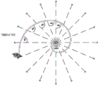
Furthermore, the guide plate is an arc-shaped plate, so the guide channel is also an equiangular spiral guide channel which gradually narrows from outside to inside, the arc line in the arc-shaped plate is an equiangular spiral line, and the guide channel in the shape is more in line with the phototactic flight behavior of moth pests (in the design, the periphery of the conical top at the center of the trapping cylinder is used as a harmful insect attracting light source, and the directional flight track of the moth pests to the light source is an equiangular spiral, as shown in fig. 9), so that the flying pests are more easily guided to fly towards the pests through holes of the corresponding trapping cylinder; the curved guide channel makes flying pests fly easily and not fly out easily. In addition, the arc-shaped guide plate has the function of preventing flying pests from escaping secondarily, after the flying pests are attracted into the guide channel, most flying pests can enter the pest trapping barrel through holes under the action of negative pressure, but a small part of flying pests can fly along the outer convex side of the guide plate and escape from the guide channel, when the flying pests fly to the outer edge position of the guide plate along the outer convex side of the guide plate, the guide plate has the function of guiding the flying pests to enter the adjacent guide channel, namely the flying pests fly along the outer convex side of the guide plate, and when the guide plate disappears suddenly, the flying pests can fly into the adjacent guide channel, so that secondary trapping of the flying pests is realized, and the trapping effect of the flying pests is ensured by the guide channels arranged in sequence along the circumferential direction.
Furthermore, the guide plate is hinged with the trapping cylinder, and is positioned in the middle of the swinging amplitude under the action of the elastic structure in an outdoor windless environment, and the inlets of all the guide channels are consistent in size, so that flying pests are uniformly trapped; and when outdoor when having wind, the guide board of windward side receives the wind force effect, can overcome elastic construction's effort, and two adjacent guide boards that correspond can open to increase windward side guide channel's area, more flight pest are also followed the wind flight this moment, and the guide channel area of windward side increases, thereby can catch more flight pest. And in this process, the guide board is the arc structure, has then increased the surface area of guide board for the wind-force grow that the guide board of windward side received, open more easily during windy environment.
Drawings
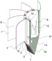
FIG. 1 is a schematic block diagram of one embodiment of the present invention;
FIG. 2 is a side view of FIG. 1;
FIG. 3 is a top view of FIG. 1;
FIG. 4 is a schematic view of the flying insect trap of FIG. 1 taken from the middle thereof;
FIG. 5 is a schematic view of the construction of the trap cartridge of FIG. 1;
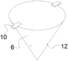
FIG. 6 is a schematic view of the construction of the cartridge top of FIG. 1;
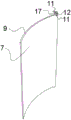
fig. 7 is a schematic structural view of the guide plate of fig. 1;
FIG. 8 is a schematic view of the bottom of the container of FIG. 1 engaged with an insect collecting bag;
FIG. 9 is a diagram of flight trajectories of flying pests.
Detailed Description
The embodiments of a flying pest trap of the present invention are shown in fig. 1 to 9: including traping a section of thick bamboo 2, the periphery of traping a section of thick bamboo 2 distributes and has a plurality ofly to be radial distribution's guide board 7 as the center, and in this embodiment, each guide board 7 is protruding arc consistent towards the direction, all forms by outer to interior constrictive guide way 8 gradually between the adjacent guide board, because guide board 7 is the arc, consequently guide way 8's the passageway wall also is the arc structure, guide way 8's cross sectional shape is just like "ox horn shape".
Traping and being provided with the mounting groove 13 that corresponds the arrangement with each arc on section of thick bamboo 2, the cross sectional shape of mounting groove is big tripe hole structure in outer little, the lower extreme of mounting groove is provided with the hinge hole, the lower extreme of guide board has with the hinge hole articulated complex downside hinge axle section, the upper end of guide board has upside hinge axle section 17, fixed cover is even had torsional spring 12 on the upside hinge axle section 17, torsional spring 12 is made by the plastics material, two fender arms 11 of torsional spring 12 keep off on traping a section of thick bamboo, the torsional spring has constituted and has been used for applying the effort so that the guide board is in the elastic construction of amplitude intermediate position in windless environment to the guide board, the guide board can be reliable elastic construction's effort and swing in windy environment.
Trap a section of thick bamboo pest clearing hole 3 that all sets up along the extending of upper and lower direction on section of thick bamboo 2 in traping between each adjacent guide board, the upper end and the lower extreme of trapping a section of thick bamboo 2 are provided with bobbin top 6 and bobbin base respectively, the bobbin top is big-end-up's back taper structure, bobbin top 6 and trapping a section of thick bamboo coaxial arrangement, bobbin top 6 upper end be provided with be used for with trap bobbin upper end stop cooperation in order to prevent bobbin top from to the falling hang along 10, the flight pest is blocked by the bobbin top and can not fly out in the trapping a section of thick bamboo pest clearing hole of opposite side by the trapping section of thick bamboo pest clearing hole of one side after flying into. The periphery of the top of the cylinder is provided with a trapping lamp bead 12.
The downside of the barrel bottom is provided with an insect collecting bag 1, the downside of the barrel bottom is also provided with an insect collecting fan 16, the insect collecting fan 16 blows downwards, the central position on the barrel bottom is provided with a barrel bottom pest through hole 14, and the barrel top and the barrel bottom pest through hole are coaxially arranged. The cartridge base includes a cartridge base plate 20 on which pest-passing holes 14 are provided, and a retainer ring 15 provided on the underside of the cartridge base plate.
The upper end symmetry of traping a section of thick bamboo is provided with two perforations, thereby iron wire or line can penetrate the perforation and constitute link 5, make things convenient for the trapper to hang and trap at suitable height.
During the use, the flight pest is caught the light attraction of traping that the lamp pearl sent by traping, flies to the guide channel that corresponds in. As shown in fig. 9, it can be known from a moth fire suppression test that when flying pests are attracted by light, the flying tracks of the flying pests are equiangular spiral shapes, the guide channel is formed by a plurality of arc-shaped guide plates in a partition manner, and arcs in the arc-shaped plates are equiangular spiral lines, so that the guide channel in the shape is more in line with the phototaxis flying behavior of the moth pests. Flying pests fly towards the pest trapping barrel through holes along the guide channel, and the flying pests are easy to fly and are difficult to fly out due to the bent guide channel; if flying pests fly and escape outwards along the outer convex side 9 of the guide plate, the flying pests can enter the next adjacent guide channel, and the escaped flying pests are trapped continuously, so that the trapping efficiency is ensured; after the flight pest enters into a section of thick bamboo of traping through traping a section of thick bamboo pest through the hole, the conical top of back taper structure hinders the flight pest and flies out by the other side of traping a section of thick bamboo, and simultaneously under the effect of negative pressure air current, the flight pest can fly downwards along the conical top, finally falls into through bobbin base pest through the hole and lures in the insect bag of gathering.
When the outdoor wind-free environment is used, under the action of the torsion spring, each guide plate is positioned at the center of the swing amplitude of the guide plate, and each guide channel is uniformly arranged to ensure uniform induction; when meetting windy environment, the flight pest also can fly along with wind, consequently mainly uses the windward side of trapper this moment to trape, when windy, receives the wind-force effect, and the guide board that corresponds can overcome the torsional spring effort and open to increase guide channel's entry size, improve and trap the effect.
Finally, it should be noted that: the above examples are only intended to illustrate the technical solution of the present invention, but not to limit it; although the present invention has been described in detail with reference to the foregoing embodiments, it will be understood by those of ordinary skill in the art that: the technical solutions described in the foregoing embodiments may still be modified, or some technical features may be equivalently replaced; and such modifications or substitutions do not depart from the spirit and scope of the corresponding technical solutions of the embodiments of the present invention.