CN113085113B - Core pulling structure for producing injection mold for rearview mirror shell - Google Patents
Core pulling structure for producing injection mold for rearview mirror shell Download PDFInfo
- Publication number
- CN113085113B CN113085113B CN202110623733.0A CN202110623733A CN113085113B CN 113085113 B CN113085113 B CN 113085113B CN 202110623733 A CN202110623733 A CN 202110623733A CN 113085113 B CN113085113 B CN 113085113B
- Authority
- CN
- China
- Prior art keywords
- sliding block
- sliding
- core
- block assembly
- rearview mirror
- Prior art date
- Legal status (The legal status is an assumption and is not a legal conclusion. Google has not performed a legal analysis and makes no representation as to the accuracy of the status listed.)
- Active
Links
Images


Classifications
-
- B—PERFORMING OPERATIONS; TRANSPORTING
- B29—WORKING OF PLASTICS; WORKING OF SUBSTANCES IN A PLASTIC STATE IN GENERAL
- B29C—SHAPING OR JOINING OF PLASTICS; SHAPING OF MATERIAL IN A PLASTIC STATE, NOT OTHERWISE PROVIDED FOR; AFTER-TREATMENT OF THE SHAPED PRODUCTS, e.g. REPAIRING
- B29C45/00—Injection moulding, i.e. forcing the required volume of moulding material through a nozzle into a closed mould; Apparatus therefor
- B29C45/17—Component parts, details or accessories; Auxiliary operations
- B29C45/40—Removing or ejecting moulded articles
- B29C45/44—Removing or ejecting moulded articles for undercut articles
-
- B—PERFORMING OPERATIONS; TRANSPORTING
- B29—WORKING OF PLASTICS; WORKING OF SUBSTANCES IN A PLASTIC STATE IN GENERAL
- B29C—SHAPING OR JOINING OF PLASTICS; SHAPING OF MATERIAL IN A PLASTIC STATE, NOT OTHERWISE PROVIDED FOR; AFTER-TREATMENT OF THE SHAPED PRODUCTS, e.g. REPAIRING
- B29C45/00—Injection moulding, i.e. forcing the required volume of moulding material through a nozzle into a closed mould; Apparatus therefor
- B29C45/17—Component parts, details or accessories; Auxiliary operations
- B29C45/26—Moulds
- B29C45/33—Moulds having transversely, e.g. radially, movable mould parts
- B29C45/332—Mountings or guides therefor; Drives therefor
-
- B—PERFORMING OPERATIONS; TRANSPORTING
- B29—WORKING OF PLASTICS; WORKING OF SUBSTANCES IN A PLASTIC STATE IN GENERAL
- B29L—INDEXING SCHEME ASSOCIATED WITH SUBCLASS B29C, RELATING TO PARTICULAR ARTICLES
- B29L2012/00—Frames
Abstract
The invention discloses a core pulling structure for an injection mold for producing rearview mirror shells, which comprises a driving unit, a first sliding block assembly, a second sliding block assembly and a third sliding block assembly, wherein the first sliding block assembly is arranged on the driving unit; the driving unit is in transmission connection with the first sliding block assembly and is used for driving the first sliding block assembly to move towards the demolding direction of the rearview mirror shell main body so as to finish two strokes of a stroke A and a stroke B; the first sliding block assembly is in transmission connection with the second sliding block assembly, and when the first sliding block assembly performs a stroke A, the second sliding block assembly simultaneously moves towards the demolding direction of the rearview mirror shell reverse buckle; the third sliding block component is in transmission connection with the first sliding block component, and the first sliding block component drives the third sliding block component to move towards the demolding direction of the rearview mirror shell main body when performing stroke B; the application especially provides a structure of loosing core for producing rear-view mirror shell injection mold, thereby has solved the mould and has needed a plurality of directions to loose core and make the comparatively complicated problem of mould structure.
Description
Technical Field
The invention relates to the technical field of mold equipment, in particular to a core pulling structure for producing an injection mold for a rearview mirror shell.
Background
An injection mold is a tool for producing plastic products; the injection molding is a processing method used for batch production of parts with complex shapes, and particularly relates to a method for injecting heated and melted plastic into a mold cavity from an injection molding machine at high pressure, cooling and solidifying to obtain a formed product, then ejecting the formed product by a mold opening ejector pin of the mold, and finishing an injection molding cycle.
The shell of automobile rearview mirror is owing to the design has the back-off, can't once only loose core when loosing core and accomplish, so need consider the core of loosing core of a plurality of directions, just can guarantee that the product takes out, but the design of loosing core of a plurality of directions can occupy great mould space to also can make the structure of mould comparatively complicated, mould manufacturing cost is higher, and the production cycle of product also increases the manufacturing cost of product.
Disclosure of Invention
To prior art's not enough and defect, this application provides a structure of loosing core for producing rear-view mirror shell injection mold specially, thereby solved the mould and need a plurality of directions to loose core and make the comparatively complicated problem of mould structure.
In order to achieve the above object, the present invention provides the following technical solutions.
A core pulling structure for producing an injection mold of a rearview mirror shell comprises a driving unit, a first sliding block assembly, a second sliding block assembly and a third sliding block assembly; the driving unit is in transmission connection with the first sliding block assembly and is used for driving the first sliding block assembly to move towards the demolding direction of the rearview mirror shell main body 100 so as to complete two strokes of stroke A and stroke B; the first sliding block assembly is in transmission connection with the second sliding block assembly, and when the first sliding block assembly performs the stroke A, the second sliding block assembly simultaneously moves towards the demolding direction of the rearview mirror shell back-off 200; the third sliding block component is in transmission connection with the first sliding block component, and the first sliding block component drives the third sliding block component to move towards the demolding direction of the rearview mirror shell main body 100 when performing stroke B; the second slider assembly is in transmission connection with the third slider assembly, and the third slider assembly can drive the second slider assembly to move towards the demoulding direction of the rearview mirror housing main body 100 when moving towards the demoulding direction of the rearview mirror housing main body 100. The beneficial effects of this technical scheme do: the first sliding block assembly can complete the design of two strokes of the stroke A and the stroke B through one driving unit, so that the utilization rate of the driving unit is improved, and the running cost of the die in the running process is reduced; and only one driving unit also enables the structure of the whole pair of dies to be simpler, and saves the production cost of the dies. First sliding block set spare just can drive second sliding block set spare when carrying out stroke A, just can drive the linkage design of second sliding block set spare and third sliding block set spare simultaneously when carrying out stroke B, makes the motion that a drive unit just can realize a plurality of subassemblies, and the process of loosing core is finished at one go for moulding plastics of product, makes production efficiency can be higher.
Further, the first slider assembly includes a first slider and a first core; the first sliding block is fixed on the first core body, and the driving unit is in transmission connection with the first sliding block. By designing the first slider and the first core as two parts, the production of the two parts can be facilitated, and the assembly of the entire set of dies can also be facilitated.
Furthermore, the first sliding block assembly also comprises a first base, and a first notch is formed in the first base; the first sliding strip is embedded in the first sliding groove, and the first sliding block can move along the track of the first sliding groove. Through the design of spout and draw runner, can make first slider can move along the orbit of spout when moving, improved the accuracy nature of moving.
Further, the second slider assembly comprises a second slider and a second core; the second sliding block is fixedly connected with the second core body; the second core body is arranged in a fit mode with the first core body, and the fit surface of the second core body and the fit surface of the first core body are inclined upwards along the demolding direction. Through the arrangement that the joint surfaces of the second core body and the first core body are both inclined downwards, when the core of the first core body is pulled, the first core body gradually supports the second core body, the height of the second core body is reduced along the track of the second notch, and the second core body can be transversely pulled out from the product.
Furthermore, a dovetail joint is arranged on the first core body, a dovetail groove is arranged on the second core body, and the dovetail joint is embedded in the dovetail groove. Through the dovetail groove and the dovetail-tongue matched design, the moving track between the first core body and the second core body is limited by the dovetail groove, the problem of deviation of the effectively avoided moving track is solved, the first core body and the second core body are embedded through the dovetail groove, and the elastic block is prevented from being separated from the sliding block.
Further, the third slide block assembly comprises a third slide block, a third core body, a slide shaft and a connecting slide block; the third sliding block and the third core body are fixed into a whole; the connecting slide block is fixed on the third slide block; the connecting sliding block is provided with a second notch, the second sliding block is embedded in the second notch, and the second sliding block can move along the second notch; the third sliding block is in transmission connection with the first sliding block through a sliding shaft. Through the design that third slider and third core body are fixed in an organic whole, make part structure simpler, reduced the installation procedure, the design that third slider and first slider transmission are connected makes the power of first slider can drive the third slider and reduced power unit.
Furthermore, a sliding hole is formed in the first sliding block, a hole shoulder is arranged at one end of the sliding hole, and a shaft shoulder is arranged at the end of the sliding shaft; the sliding shaft penetrates through the sliding hole, and the shaft shoulder can abut against the hole shoulder after the first sliding block assembly completes the stroke A. The shaft shoulder is abutted to the hole shoulder, the first sliding block assembly can drive the third sliding block when the stroke B is carried out, and the transmission structure that the first sliding block drives the third sliding block is simplified.
Further, the first sliding block assembly further comprises an elastic block and a spring; the spring is used for pushing the elastic block to abut against the third sliding block. Through the bullet piece design, can avoid first slider component to carry out the stroke A time and drive the third slider removal in advance because of the effect of frictional force.
Furthermore, an elastic block groove is formed in the first sliding block, and a first sliding table which is obliquely protruded is arranged on the elastic block groove; the elastic block is provided with an inclined second sliding table; the bullet piece inlays in the bullet piece recess, and first slip table and the laminating of second slip table. When the first sliding block assembly carries out the stroke B, the first sliding block can push the elastic block on the first sliding table and the second sliding table. The design of first slip table and the laminating of second slip table, first slider can extrude the bullet piece when removing, makes the bullet piece not blockking the third slider and removes, need not extra power pack and drives the bullet piece.
Furthermore, the driving unit is a hydraulic cylinder, and the hydraulic pressure of the injection molding machine can be used as a power source by the driving unit through the design that the driving unit is the hydraulic cylinder, so that the cost of the power source is reduced.
Drawings
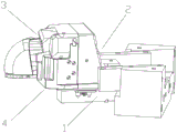
Fig. 1 is a schematic view of the overall structure of the present invention.
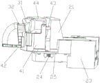
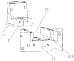
FIG. 2 is a schematic view of a first slider assembly of the present invention.
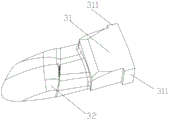
FIG. 3 is a schematic view A of a second slider assembly of the present invention.
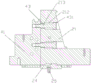
FIG. 4 is a schematic view of a third slider assembly of the present invention.
Fig. 5 is a schematic structural diagram after the stroke a of the present invention is completed.
Fig. 6 is a schematic diagram showing the effect of the present invention on separation from the product after completion of stroke B.
FIG. 7 is a cross-sectional view of a first slider assembly of the present invention mated with a portion of a second slider assembly.
FIG. 8 is a partial cross-sectional view of a first slider assembly of the present invention.
Fig. 9 is a schematic structural view of the bullet block of the present invention.
FIG. 10 is a schematic view of a first slider configuration of the present invention.
FIG. 11 is a schematic view of the third slide block abutting the spring block of the present invention.
Fig. 12 is an enlarged view of a portion of fig. 11 of the present invention.
FIG. 13 is a schematic view of the installation relationship of the first sliding block and the first base according to the present invention.
FIG. 14 is a schematic view of the connecting block of the present invention.
FIG. 15 is a schematic view B of a second slider assembly of the present invention.
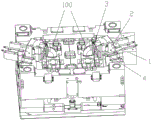
Fig. 16 is a schematic view of the structure of the present invention mounted on a mold.
Fig. 17 is a structural view of a mirror housing.
In the figure, 1 is a driving unit; 2 is a first slide block component; 3 is a second slider assembly; 4 is a third slider assembly; 21 is a first slide block; 22 is a first core; 23 is a first base; 24 is a bullet block; 25 is a spring; 31 is a second slide block; 32 is a second core; 41 is a third slide block; 42 is a third core; 43 is a sliding shaft; 211 is a first slide bar; 212 is a slide hole; 213 is a hole shoulder; 214 is a spring block groove; 215 is a first sliding table; 221 is a dovetail; 231 is a first notch; 232 is a first chute; 241 is a second sliding table; 311 is a second slide bar; 322 is a dovetail groove; 431 is a shaft shoulder; 44 is a connecting slide block; 441 is a second notch; 442 is a second chute; 100 is a rearview mirror housing main body; 200 is a back-off of the mirror housing.
Detailed Description
The invention is further explained with reference to the drawings.
The first embodiment is as follows:
as shown in fig. 1 to 17, a core pulling structure for producing an injection mold for a rearview mirror housing includes a driving unit 1, a first slider assembly 2, a second slider assembly 3, and a third slider assembly 4.
The core-pulling process is divided into a stroke A and a stroke B, and continuous work is performed between the stroke A and the stroke B.
The process of the stroke A is as follows: the first slider assembly 2 moves toward the mirror housing main body 100 in the mold releasing direction, and the second slider assembly 3 moves toward the mirror housing inverted buckle 200 in the mold releasing direction while the first slider assembly 2 moves.
The process of the stroke B is as follows: after the first slider assembly 2 completes the stroke a, it continues to move towards the demolding direction of the mirror housing main body 100, and at the same time, the first slider assembly 2 drives the second slider assembly 3 and the third slider assembly 4 to move towards the demolding direction of the mirror housing main body 100.
And finishing the demolding of the rearview mirror shell by the stroke A and the stroke B.
The driving unit 1 is a hydraulic cylinder, and drives the first slide block assembly 2 to move by using the hydraulic pressure of the injection molding machine as a power source.
The first slider assembly 2 includes a first slider 21, a first core 22, and a first base 23.
The first slide block 21 is fixed on the first core 22, the driving unit 1 is in transmission connection with the first slide block 21, and the driving unit 1 can drive the first slide block 21 to move.
The first base 23 is provided with a first notch 231; first recess 231 bottom is equipped with first spout 232, and first slider 21 bottom is equipped with first draw runner 211, and first slider 21 is installed on first base 23, and just first draw runner 211 inlays in first spout 232, and first spout 232 and first draw runner 211's cooperation can avoid first slider 21 vertically to break away from first base 23, still can guarantee simultaneously that first slider 21 moves on first base 23 along first spout 232.
The second slider assembly 3 includes a second slider 31 and a second core 32; the second slider 31 and the second core 32 are fixed integrally.
The bottom of the second core 32 is provided with an inclined surface inclined upwards along the demoulding direction of the rearview mirror housing inverted buckle 200, the bottom of the first core 22 is provided with an inclined surface inclined upwards along the demoulding direction of the rearview mirror housing inverted buckle 200, the second core 32 is attached to the inclined surface of the first core 22, and when the first core 22 moves transversely, the second core 32 can move longitudinally under the action of the first core 22.
The dovetail 221 is provided on the inclined surface of the first core 22, the dovetail groove 322 is provided on the inclined surface of the second core 32, and the dovetail 221 is embedded in the dovetail groove 322 when the second core 32 is attached to the inclined surface of the first core 22.
The third slider assembly 4 includes a third slider 41, a third core 42, a slide shaft 43, and a connecting slider 44.
The connecting slider 44 is provided with a second notch 441, and two sides of the second notch 441 are provided with second sliding grooves 442.
The second slide bar 311 is disposed on two sides of the second slider 31, the second slider 31 is embedded in the second notch 441, the second slide bar 311 is embedded in the second sliding slot 442, the second slider 31 can move in the second notch 441 along a direction in which the second slide bar 311 and the second sliding slot 442 are matched, and a direction in which the second slider 31 moves in the second notch 441 is a demolding direction of the rearview mirror housing inverted buckle 200.
Through the design of the dovetail block 221 and the dovetail groove 322, when the first core 22 moves towards the demolding direction of the mirror housing main body 100, a pulling force moving towards the demolding direction of the mirror housing inverted buckle 200 is applied to the second core 32, and the second sliding block 31 is pulled to move downwards along the second notch 441; without the dovetail block 221 and the dovetail groove 322, the second slider 31 can slide down only after losing the support of the first core 22 by its own weight, and the speed or distance of the sliding down is easily affected by the friction between the second slider 31 and the connecting slider 44.
The third slider 41 and the third core 42 are integrally formed, and the sliding shaft 43 is fixed on the third slider 41; a shaft shoulder 431 is arranged at the end part of the sliding shaft 43; the first slider 21 is provided with a slide hole 212, a hole shoulder 213 is provided at one end of the slide hole 212, and the slide shaft 43 is fitted in the slide hole 212 and can move in the slide hole 212.
After the stroke a is completed, the shoulder 431 will abut against the shoulder 213, and the first slide 21 will move under the action of the shoulder 431 and the shoulder 213 while continuing the stroke B.
The first slider assembly 2 further comprises a spring block 24 and a spring 25.
The elastic block 24 is provided with an inclined second sliding table 241, the first sliding block 21 is provided with an elastic block groove 214, and the elastic block groove 214 is provided with an inclined convex first sliding table 215.
The elastic block 24 is pushed by the spring 25 to enable the elastic block 24 to enter the elastic block groove 214, the first sliding table 215 is attached to the second sliding table 241 after the elastic block 24 enters the elastic block groove 214, and meanwhile the elastic block 24 abuts against the third sliding block 41 to block the third sliding block 41 from moving.
When the first slide block assembly 2 performs the stroke a, the third slide block 41 is blocked by the elastic block 24 and cannot move, so that the third slide block 41 is prevented from moving in advance under the action of friction force.
When the first sliding block 21 performs the stroke a, the elastic block 24 is extruded under the matching of the first sliding table 215 and the second sliding table 241, when the stroke a is completed, the elastic block 24 is extruded to a position where the third sliding block 41 is no longer blocked, at this time, the first sliding block 21 can drive the second sliding block 31 and the third sliding block 41 to perform the stroke B together, after the moving distance of the stroke B is completed, the housing of the rearview mirror is completely separated from the three cores, and the core pulling operation is completed.
The above description is only a preferred embodiment of the present invention, and all equivalent changes or modifications of the structure, characteristics and principles described in the present invention are included in the scope of the present invention.
Claims (8)
1. The utility model provides a structure of loosing core for producing rear-view mirror shell injection mold which characterized in that: the core pulling structure for producing the injection mold of the rearview mirror shell comprises a driving unit (1), a first sliding block assembly (2), a second sliding block assembly (3) and a third sliding block assembly (4);
the driving unit (1) is in transmission connection with the first sliding block assembly (2) and is used for driving the first sliding block assembly (2) to move towards the demolding direction of the rearview mirror shell main body to complete two strokes of a stroke A and a stroke B;
the first sliding block assembly (2) is in transmission connection with the second sliding block assembly (3), and when the first sliding block assembly (2) performs a stroke A, the second sliding block assembly (3) simultaneously moves towards the demolding direction of the rearview mirror shell reverse buckle;
the third sliding block assembly (4) is in transmission connection with the first sliding block assembly (2), and the first sliding block assembly (2) drives the third sliding block assembly (4) to move towards the demolding direction of the rearview mirror shell main body during the stroke B;
the second sliding block assembly (3) is in transmission connection with the third sliding block assembly (4), and the third sliding block assembly (4)) can drive the second sliding block assembly (3) to move towards the demoulding direction of the rearview mirror shell main body when moving towards the demoulding direction of the rearview mirror shell main body;
the first slider assembly (2) comprises a first slider (21) and a first core (22); the first sliding block (21) is fixed on the first core body (22), and the driving unit (1) is in transmission connection with the first sliding block (21);
the second slider assembly (3) comprises a second slider (31) and a second core (32); the second sliding block (31) is fixedly connected with the second core body (32); the second core body (32) is attached to the first core body (22);
the third slide block assembly (4) comprises a third slide block (41), a third core body (42), a slide shaft (43) and a connecting slide block (44);
the third slide block (41) and the third core body (42) are fixed into a whole;
the connecting slide block (44) is fixed on the third slide block (41); the connecting sliding block (44) is provided with a second notch (441), the second sliding block (31) is embedded in the second notch (441), and the second sliding block (31) can move along the second notch (441);
the third sliding block (41) is in transmission connection with the first sliding block (21) through the sliding shaft (43).
2. The core pulling structure for producing the injection mold for the rearview mirror housing as claimed in claim 1, wherein: the first sliding block assembly (2) further comprises a first base (23), and a first notch (231) is formed in the first base (23);
the bottom of the first notch (231) is provided with a first sliding groove (232), the bottom of the first sliding block (21) is provided with a first sliding strip (211), the first sliding block (21) is installed in the first notch (231), the first sliding strip (211) is embedded in the first sliding groove (232), and the first sliding block (21) can move along the track of the first sliding groove (232).
3. The core pulling structure for producing the injection mold for the rearview mirror housing as claimed in claim 2, wherein: the binding surfaces of the second core body (32) and the first core body (22) are inclined upwards along the back-off demoulding direction of the rearview mirror shell.
4. The core pulling structure for producing the injection mold for the rearview mirror housing as claimed in claim 3, wherein: be equipped with forked tail (221) on first core (22), be equipped with dovetail (322) on second core (32), forked tail (221) inlay in dovetail (322).
5. The core pulling structure for producing the injection mold for the rearview mirror housing as claimed in claim 4, wherein: a sliding hole (212) is arranged on the first sliding block (21), a hole shoulder (213) is arranged at one end part of the sliding hole (212),
a shaft shoulder (431) is arranged at the end part of the sliding shaft (43);
the sliding shaft (43) penetrates through the sliding hole (212), and the shaft shoulder (431) can abut against the hole shoulder (213) after the first sliding block assembly (2) completes the stroke A.
6. The core pulling structure for producing the injection mold for the rearview mirror housing as claimed in claim 5, wherein: the first slider assembly (2) further comprises a spring block (24) and a spring (25);
the spring (25) is used for pushing the elastic block (24) to abut against the third sliding block (41).
7. The core pulling structure for producing the injection mold for the rearview mirror housing as claimed in claim 6, wherein: an elastic block groove (214) is formed in the first sliding block (21), and a first sliding table (215) which protrudes in an inclined mode is arranged on the elastic block groove (214);
the elastic block (24) is provided with an inclined second sliding table (241);
the elastic block (24) is embedded in the elastic block groove (214), and the first sliding table (215) is attached to the second sliding table (241);
when the first slide block assembly (2) performs a stroke B, the first slide block (21) can push the elastic block (24) on the first sliding table (215) and the second sliding table (241).
8. The core pulling structure for producing the injection mold for the rearview mirror housing as claimed in claim 1, wherein: the driving unit (1) is a hydraulic cylinder.
Priority Applications (1)
| Application Number | Priority Date | Filing Date | Title |
|---|---|---|---|
| CN202110623733.0A CN113085113B (en) | 2021-06-04 | 2021-06-04 | Core pulling structure for producing injection mold for rearview mirror shell |
Applications Claiming Priority (1)
| Application Number | Priority Date | Filing Date | Title |
|---|---|---|---|
| CN202110623733.0A CN113085113B (en) | 2021-06-04 | 2021-06-04 | Core pulling structure for producing injection mold for rearview mirror shell |
Publications (2)
| Publication Number | Publication Date |
|---|---|
| CN113085113A CN113085113A (en) | 2021-07-09 |
| CN113085113B true CN113085113B (en) | 2021-08-20 |
Family
ID=76664567
Family Applications (1)
| Application Number | Title | Priority Date | Filing Date |
|---|---|---|---|
| CN202110623733.0A Active CN113085113B (en) | 2021-06-04 | 2021-06-04 | Core pulling structure for producing injection mold for rearview mirror shell |
Country Status (1)
| Country | Link |
|---|---|
| CN (1) | CN113085113B (en) |
Families Citing this family (2)
| Publication number | Priority date | Publication date | Assignee | Title |
|---|---|---|---|---|
| CN114161669B (en) * | 2022-02-09 | 2022-06-28 | 宁波周龙塑胶模具有限公司 | Injection mold of plastic part for automobile |
| CN115556319B (en) * | 2022-10-18 | 2023-08-04 | 合肥昊翔汽车零部件有限公司 | Injection molding demolding mechanical arm for automobile rearview mirror outer shell |
Citations (14)
| Publication number | Priority date | Publication date | Assignee | Title |
|---|---|---|---|---|
| JP3828569B1 (en) * | 2005-10-19 | 2006-10-04 | ダイワ精機株式会社 | Mold for headlamp lens manufacturing |
| JP2007136809A (en) * | 2005-11-17 | 2007-06-07 | Fuji Heavy Ind Ltd | Resin molding mold |
| CN102029667A (en) * | 2009-09-30 | 2011-04-27 | 厦门市欣成业工贸有限公司 | Die structure for manufacturing rearview mirror |
| JP2012061730A (en) * | 2010-09-16 | 2012-03-29 | Shimada Precision Kk | Injection mold |
| CN103407112A (en) * | 2013-08-29 | 2013-11-27 | 丹阳市新威汽车部件有限公司 | T-shaped core-pulling mechanism of injection mould |
| CN103934978A (en) * | 2013-01-23 | 2014-07-23 | 厦门市欣成业工贸有限公司 | Plastic mold capable of finishing back-off core pulling of product |
| CN104210070A (en) * | 2014-09-18 | 2014-12-17 | 重庆长安汽车股份有限公司 | Core pulling mould of automobile outside rear-view mirror |
| CN104325608A (en) * | 2014-10-17 | 2015-02-04 | 宁波双林模具有限公司 | Three-linkage synthesis core-pulling device of injection mould |
| CN204235834U (en) * | 2014-10-31 | 2015-04-01 | 浙江凯华模具有限公司 | Injection mold horizontal vertical directional combination core-pulling mechanism |
| CN204869473U (en) * | 2015-04-04 | 2015-12-16 | 忠信制模(东莞)有限公司 | Improved generation automobile rearview mirror's forming die |
| CN207014712U (en) * | 2017-06-28 | 2018-02-16 | 顺德职业技术学院 | The side core-pulling structure of automobile rearview mirror injection mold |
| CN207206987U (en) * | 2017-08-02 | 2018-04-10 | 象山宁越模具有限公司 | A kind of side core drawing structure for automobile-used valve body manufacture mould |
| CN211138010U (en) * | 2019-10-16 | 2020-07-31 | 台州市黄岩茂荣塑模有限公司 | Secondary sliding block demoulding mechanism for complex area of automobile rearview mirror |
| CN211807598U (en) * | 2020-09-07 | 2020-10-30 | 常源科技(天津)有限公司 | Non-planar intersection slider back-off structure of loosing core |
-
2021
- 2021-06-04 CN CN202110623733.0A patent/CN113085113B/en active Active
Patent Citations (14)
| Publication number | Priority date | Publication date | Assignee | Title |
|---|---|---|---|---|
| JP3828569B1 (en) * | 2005-10-19 | 2006-10-04 | ダイワ精機株式会社 | Mold for headlamp lens manufacturing |
| JP2007136809A (en) * | 2005-11-17 | 2007-06-07 | Fuji Heavy Ind Ltd | Resin molding mold |
| CN102029667A (en) * | 2009-09-30 | 2011-04-27 | 厦门市欣成业工贸有限公司 | Die structure for manufacturing rearview mirror |
| JP2012061730A (en) * | 2010-09-16 | 2012-03-29 | Shimada Precision Kk | Injection mold |
| CN103934978A (en) * | 2013-01-23 | 2014-07-23 | 厦门市欣成业工贸有限公司 | Plastic mold capable of finishing back-off core pulling of product |
| CN103407112A (en) * | 2013-08-29 | 2013-11-27 | 丹阳市新威汽车部件有限公司 | T-shaped core-pulling mechanism of injection mould |
| CN104210070A (en) * | 2014-09-18 | 2014-12-17 | 重庆长安汽车股份有限公司 | Core pulling mould of automobile outside rear-view mirror |
| CN104325608A (en) * | 2014-10-17 | 2015-02-04 | 宁波双林模具有限公司 | Three-linkage synthesis core-pulling device of injection mould |
| CN204235834U (en) * | 2014-10-31 | 2015-04-01 | 浙江凯华模具有限公司 | Injection mold horizontal vertical directional combination core-pulling mechanism |
| CN204869473U (en) * | 2015-04-04 | 2015-12-16 | 忠信制模(东莞)有限公司 | Improved generation automobile rearview mirror's forming die |
| CN207014712U (en) * | 2017-06-28 | 2018-02-16 | 顺德职业技术学院 | The side core-pulling structure of automobile rearview mirror injection mold |
| CN207206987U (en) * | 2017-08-02 | 2018-04-10 | 象山宁越模具有限公司 | A kind of side core drawing structure for automobile-used valve body manufacture mould |
| CN211138010U (en) * | 2019-10-16 | 2020-07-31 | 台州市黄岩茂荣塑模有限公司 | Secondary sliding block demoulding mechanism for complex area of automobile rearview mirror |
| CN211807598U (en) * | 2020-09-07 | 2020-10-30 | 常源科技(天津)有限公司 | Non-planar intersection slider back-off structure of loosing core |
Also Published As
| Publication number | Publication date |
|---|---|
| CN113085113A (en) | 2021-07-09 |
Similar Documents
| Publication | Publication Date | Title |
|---|---|---|
| CN113085113B (en) | Core pulling structure for producing injection mold for rearview mirror shell | |
| CN215039969U (en) | Z-shaped guide rail structure of thin-wall high-rigidity automobile bumper mould | |
| CN211031091U (en) | Injection mold capable of automatically demolding concave parts of automobile | |
| CN211105383U (en) | C-shaped plate production die device | |
| CN110154330B (en) | Core-pulling ejection mechanism of injection mold | |
| CN209832437U (en) | Electric vehicle front wall panel mold with straight top and inclined top combined demolding mechanism | |
| CN211165131U (en) | Large-angle inclined core-pulling mechanism of automobile column interior trimming panel mold | |
| CN113733491A (en) | Secondary core pulling structure for injection mold | |
| CN209832480U (en) | Electric vehicle plastic part injection mold with inclined top built-in thimble demoulding mechanism | |
| CN211165129U (en) | Small sliding block driving large sliding block core pulling mechanism for box body mold of complex glove box of passenger vehicle | |
| CN216466006U (en) | Demoulding device for automobile plastic part | |
| CN219256328U (en) | Injection mold for household article structural member | |
| CN217597675U (en) | Mold for folding transmission mechanism of rearview mirror | |
| CN214773351U (en) | Long slider structure of mould | |
| CN220219510U (en) | Electric tricycle front headlight face guard mould with interior drawing of patterns mechanism | |
| CN217258132U (en) | Mold with product demolding structure capable of being broken off for manufacturing rear shell | |
| CN219650481U (en) | Demoulding and ejection device for automobile structural part | |
| CN211941926U (en) | Injection mold | |
| CN212653807U (en) | It retreats and revolves taking off and ejecting synchronous mold processing to advance gluey side product | |
| CN215472824U (en) | Core-pulling sliding block structure for automotive interior trim part | |
| CN211105382U (en) | Blank head device of die device | |
| CN214605624U (en) | Inverted synchronous ejection mechanism of high-gloss double-material injection mold | |
| CN216635252U (en) | Forced demoulding structure of injection mould | |
| CN212097290U (en) | Injection mold for automotive interior decoration panel | |
| CN209920459U (en) | But quick replacement's mold core mold insert mechanism |
Legal Events
| Date | Code | Title | Description |
|---|---|---|---|
| PB01 | Publication | ||
| PB01 | Publication | ||
| SE01 | Entry into force of request for substantive examination | ||
| SE01 | Entry into force of request for substantive examination | ||
| GR01 | Patent grant | ||
| GR01 | Patent grant |