CN113084561A - Thin-wall box body clamp mechanism - Google Patents
Thin-wall box body clamp mechanism Download PDFInfo
- Publication number
- CN113084561A CN113084561A CN202110308813.7A CN202110308813A CN113084561A CN 113084561 A CN113084561 A CN 113084561A CN 202110308813 A CN202110308813 A CN 202110308813A CN 113084561 A CN113084561 A CN 113084561A
- Authority
- CN
- China
- Prior art keywords
- plate
- positioning
- workpiece
- thin
- base
- Prior art date
- Legal status (The legal status is an assumption and is not a legal conclusion. Google has not performed a legal analysis and makes no representation as to the accuracy of the status listed.)
- Granted
Links
Images


Classifications
-
- B—PERFORMING OPERATIONS; TRANSPORTING
- B23—MACHINE TOOLS; METAL-WORKING NOT OTHERWISE PROVIDED FOR
- B23Q—DETAILS, COMPONENTS, OR ACCESSORIES FOR MACHINE TOOLS, e.g. ARRANGEMENTS FOR COPYING OR CONTROLLING; MACHINE TOOLS IN GENERAL CHARACTERISED BY THE CONSTRUCTION OF PARTICULAR DETAILS OR COMPONENTS; COMBINATIONS OR ASSOCIATIONS OF METAL-WORKING MACHINES, NOT DIRECTED TO A PARTICULAR RESULT
- B23Q3/00—Devices holding, supporting, or positioning work or tools, of a kind normally removable from the machine
- B23Q3/02—Devices holding, supporting, or positioning work or tools, of a kind normally removable from the machine for mounting on a work-table, tool-slide, or analogous part
- B23Q3/06—Work-clamping means
- B23Q3/08—Work-clamping means other than mechanically-actuated
- B23Q3/082—Work-clamping means other than mechanically-actuated hydraulically actuated
-
- Y—GENERAL TAGGING OF NEW TECHNOLOGICAL DEVELOPMENTS; GENERAL TAGGING OF CROSS-SECTIONAL TECHNOLOGIES SPANNING OVER SEVERAL SECTIONS OF THE IPC; TECHNICAL SUBJECTS COVERED BY FORMER USPC CROSS-REFERENCE ART COLLECTIONS [XRACs] AND DIGESTS
- Y02—TECHNOLOGIES OR APPLICATIONS FOR MITIGATION OR ADAPTATION AGAINST CLIMATE CHANGE
- Y02E—REDUCTION OF GREENHOUSE GAS [GHG] EMISSIONS, RELATED TO ENERGY GENERATION, TRANSMISSION OR DISTRIBUTION
- Y02E60/00—Enabling technologies; Technologies with a potential or indirect contribution to GHG emissions mitigation
- Y02E60/10—Energy storage using batteries
Abstract
The invention discloses a thin-wall box body clamp mechanism, which comprises: the device comprises a base assembly, a positioning mechanism, a hydraulic fixing mechanism and a pressing mechanism; a base assembly, comprising: the positioning plate, the left side plate and the right side plate are connected in a U shape, and the inner side of the positioning plate is used for placing a workpiece; the positioning mechanism is arranged on the upper side of the base assembly and used for positioning a workpiece; the hydraulic fixing mechanism is arranged on the inner side of the base assembly; the pressing mechanism is arranged on the upper sides of the left side plate and the right side plate and connected with the left side plate and the right side plate; the positioning mechanism, the hydraulic fixing mechanism and the pressing mechanism are respectively contacted with the periphery of the workpiece to press the workpiece at multiple points. The invention adopts an ingenious mechanical structure, the mechanism has simple structure, low matching requirement, convenient processing, low cost and convenient and labor-saving assembly, and the deformation of the workpiece in the processing process is ensured by positioning the workpiece through two pins on one side, hydraulically clamping the workpiece and adjusting the pressing force through pressure in the workpiece mounting and clamping process.
Description
Technical Field
The invention discloses a thin-wall box body clamp mechanism and relates to the technical field of machining.
Background
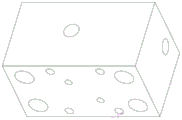
In the machining process, various shell machining requirements are high, requirements for shell inner holes, end faces and end face pin holes are high, the requirements for machining of common shells and traditional clamp structures can meet the machining requirements, operation is complex, efficiency is low, the machining requirements cannot be met for certain thin-wall shells, the shells deform seriously, coaxiality is out of tolerance, and pin hole position degree is out of tolerance.
Disclosure of Invention
Aiming at the defects in the prior art, the invention provides a thin-wall box body clamp mechanism which is supported and pressed by multiple points to eliminate various errors caused by shell deformation.
In order to achieve the purpose, the technical scheme adopted by the invention is as follows: a thin-walled box clamp mechanism comprising: the device comprises a base assembly, a positioning mechanism, a hydraulic fixing mechanism and a pressing mechanism;
a base assembly, comprising: the positioning plate, the left side plate and the right side plate are connected in a U shape, and the inner side of the positioning plate is used for placing a workpiece;
the positioning mechanism is arranged on the upper side of the base assembly and used for positioning a workpiece;
the hydraulic fixing mechanism is arranged on the inner side of the base assembly;
the pressing mechanism is arranged on the upper sides of the left side plate and the right side plate and connected with the left side plate and the right side plate;
the positioning mechanism, the hydraulic fixing mechanism and the pressing mechanism are respectively contacted with the periphery of the workpiece to press the workpiece at multiple points.
Furthermore, the locating plate is installed on the bottom plate, the left side plate and the right side plate are installed at two ends of the locating plate and are connected with the bottom plate, the locating mechanism is installed on the locating plate, a plurality of reinforcing ribs are arranged between the left side plate and the right side plate and between the left side plate and the right side plate, and 4 reinforcing ribs are installed in the front of and behind the left side plate and the right side plate and are connected with the bottom plate.
Further, the positioning mechanism includes: a positioning block and a positioning pin mechanism; the positioning block is arranged on the positioning plate, the positioning pin mechanisms are arranged on the bottom plate and positioned at two ends of the bottom plate, and the workpiece is positioned and arranged on the bottom plate through the bottom positioning block and the positioning pin mechanisms; the locating pin mechanism includes: the workpiece is positioned on one surface of the workpiece by the aid of the diamond pins and the cylindrical pins, and the workpiece is positioned and mounted on the bottom plate by the aid of the positioning blocks and the positioning pin mechanisms on the lower side.
Further, the hydraulic fixing mechanism includes: the oil pressure gauge comprises a lever oil cylinder seat component, an auxiliary oil cylinder seat component, an oil pressure gauge base and an oil duct conversion block; the lever oil cylinder base is arranged on the positioning plate, the upper side of the lever oil cylinder base is provided with the pressing plate assembly, and the pressing plate assembly is positioned on two sides of the positioning mechanism;
the auxiliary oil cylinder seat assemblies are arranged on the two side plates, the auxiliary oil cylinder seat is provided with a coarse limiting screw, and the two side plates are respectively provided with the two auxiliary oil cylinder seat assemblies for performing coarse limiting on the position of a workpiece when the workpiece is assembled; after the workpiece is installed, the coarse limiting screw is slowly started to contact the workpiece by the driving of the auxiliary oil cylinder seat assembly, and the effect of supporting the workpiece is achieved;
the oil pressure gauge is arranged on the left side plate, the oil pressure gauge is arranged on the oil pressure gauge base, the oil level pressure value can be seen through the oil pressure gauge, the oil duct conversion block is arranged on the oil pressure gauge base, an oil duct pipeline is arranged in the oil duct conversion block, and the oil duct pipeline is connected to the lever oil cylinder seat component and the auxiliary oil cylinder seat component.
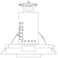
Further, the pressing mechanism comprises: the hinge base is arranged on a side plate on one side, the hinge base is in a U-shaped groove design, the turning plate supporting seat is arranged on a side plate on the other side, one side of the auxiliary turning plate is hinged with the hinge base, the other side of the auxiliary turning plate is in contact connection with the turning plate supporting seat, the pressing plate bolt is arranged on the side edge of the turning plate supporting seat, when the position of the auxiliary turning plate is adjusted, the pressing plate bolt extends out of a certain length and then is fixed to rotate by a first nut, the turning pressing plate is abutted against the auxiliary turning plate through the top of the pressing plate bolt, a second nut is arranged on the turning pressing plate to compress the auxiliary turning plate, the turning plate bolt fixes the auxiliary turning plate on the hinge base to realize the turning of the auxiliary turning plate, the auxiliary turning plate is in a rectangular shape, and one end of the auxiliary turning plate is, the supplementary board that turns over on set up a plurality of bar holes, the bar hole is two and sets up, turn over the board supporting seat and be protruding type setting, its top contacts with the supplementary arch that turns over the board.
Furthermore, a supporting screw is arranged on the auxiliary turning plate and is in contact with the workpiece on the lower side for pressing the workpiece.
Furthermore, the number of the pressing mechanisms is at least 1, and the plurality of pressing mechanisms are arranged in parallel.
Furthermore, a bottom plate positioning pin is arranged below the bottom plate, and the bottom plate is connected with the workbench through the bottom plate positioning pin.
Furthermore, the number of the positioning blocks is two, and the two positioning blocks are symmetrically arranged on the positioning plate.
Has the advantages that:
the clamping mechanism has the advantages that the defects of complex operation, easy deformation during pressing, low efficiency in the clamping and aligning process, poor auxiliary supporting effect and the like of the traditional box body machining and pressing mode are overcome, the clamping mechanism is positioned by two pins on one surface, the workpiece clamping process is hydraulically controlled, the auxiliary supporting oil cylinder is arranged in the clamping mechanism, the clamping force of the workpiece is adjusted through a pressure value, the damping effect is realized, the adjustment is convenient, and the workpiece does not need to be aligned before and after the workpiece is clamped; the base sets up the locating pin, and the frock is changed and also need not the alignment to alleviate workman's intensity of labour of operation, shorten the time of work piece dress card, improve machining efficiency's purpose.
The invention adopts an ingenious mechanical structure, the mechanism has simple structure, low matching requirement, convenient processing, low cost and convenient and labor-saving assembly, and the deformation of the workpiece in the processing process is ensured by positioning the workpiece through two pins on one side, hydraulically clamping the workpiece and adjusting the pressing force through pressure in the workpiece mounting and clamping process.
Drawings
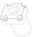
FIG. 1 is a perspective view of the clamp mechanism of the present invention;
FIG. 2 is a front view of the clamp of the present invention;
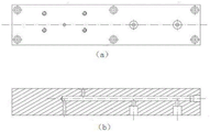
FIG. 3 is a top view of the clamp of the present invention;
FIG. 4 is a left side view of the clamp of the present invention;
FIG. 5 is a block diagram of the base plate of the present invention;
FIG. 6 is a block diagram of the right side plate of the present invention;
FIG. 7 is a structural view of the left side plate of the present invention;
FIG. 8 is a structural view of the auxiliary flap of the present invention;
FIG. 9 is a structural view of the flap support base of the present invention;
FIG. 10 is a front view of the platen bolt of the present invention;
FIG. 11 is a block diagram of the hinge base of the present invention;
FIG. 12 is a block diagram of the auxiliary cylinder assembly of the present invention;
FIG. 13 is a block diagram of the lever cylinder assembly of the present invention;
fig. 14 is a structural view of an oil passage switching block of the present invention;
FIG. 15 is a schematic structural view of a base of an oil pressure gauge according to the present invention (a is a front view, and b is a cross-sectional view);
FIG. 16 is a block diagram of the positioning block of the case of the present invention;
fig. 17 is a schematic structural view of a cylindrical pin boss according to the present invention (a is a front view, and b is a plan view);
FIG. 18 is a schematic structural view of a diamond pin boss of the present invention (a is a front view, and b is a top view);
FIG. 19 is a structural view of a bottom plate positioning pin of the present invention (a is a front view, b is a top view);
FIG. 20 is a perspective view of an embodiment of the thin wall box clamp mechanism of the present invention;
FIG. 21 is a schematic diagram of an embodiment of the thin-walled case clamp mechanism of the present invention;
in the figure: the hydraulic oil cylinder comprises a base plate 1, a positioning plate 2, a right side plate 3, a nut 4, a pressure plate bolt 5, a nut M16 with a shoulder 6, a turnover pressure plate 7, a turnover support seat 8, an auxiliary turnover plate 9, a support screw rod 10, an auxiliary oil cylinder assembly 11, a left side plate 12, an oil pressure gauge base 13, an oil pressure gauge 14, an oil passage conversion block 15, a reinforcing rib 16, a lever oil cylinder assembly 17, a positioning block 18, a diamond pin 19, a pressure plate assembly 20, a hinge base 21, a hinge base 22, a turnover plate bolt 23, a cylindrical pin 24, a coarse limit screw rod 25, an internal hexagonal screw 25, a workpiece 26, a base plate positioning pin 27.
Detailed Description
The following describes the embodiments in further detail with reference to the accompanying drawings. The following examples are only for illustrating the technical solutions of the present invention more clearly, and the protection scope of the present invention is not limited thereby.
In the description of the present invention, it should be noted that the terms "upper", "lower", "front", "rear", "left", "right", "vertical", "inner", "outer", etc., indicate orientations or positional relationships based on the orientations or positional relationships shown in the drawings, and are only for convenience of description and simplicity of description, but do not indicate or imply that the device or element being referred to must have a particular orientation, be constructed and operated in a particular orientation, and thus, should not be construed as limiting the present invention.
In the description of the present invention, it should be noted that, unless otherwise explicitly specified or limited, the terms "mounted," "connected," and "connected" are to be construed broadly, e.g., as meaning either a fixed connection, a removable connection, or an integral connection; can be mechanically or electrically connected; may be directly connected or indirectly connected through an intermediate. The specific meanings of the above terms in the present invention can be understood in specific cases to those skilled in the art.
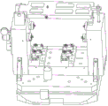
As shown in fig. 1 to 7, a thin-wall box clamp mechanism includes: the device comprises a base assembly, a positioning mechanism, a hydraulic fixing mechanism and a pressing mechanism;
a base assembly, comprising: the positioning plate 2, the left side plate 12 and the right side plate 3 are connected in a U shape, and the inner side of the positioning plate is used for placing a workpiece 26;
a positioning mechanism mounted on the upper side of the base assembly for positioning a workpiece 26;
the hydraulic fixing mechanism is arranged on the inner side of the base assembly;
the pressing mechanism is arranged on the upper sides of the left side plate 12 and the right side plate 3 and is connected with the left side plate 12 and the right side plate 3;
the positioning mechanism, the hydraulic fixing mechanism and the pressing mechanism are respectively contacted with the periphery of the workpiece 26 to press the workpiece 26 at multiple points.
The positioning plate 2 is arranged on the bottom plate 1 through inner hexagonal screws 25 and positioning pins, the left side plate 12 and the right side plate 3 are fixed on the positioning plate 2 and the bottom plate 1 through a plurality of inner hexagonal screws 25 and pins, the positioning mechanism is arranged on the positioning plate 2, a plurality of reinforcing ribs 16 are arranged between the left side plate 3 and the positioning plate 2, and the front and the back of the left side plate 3 and the right side plate 3 are provided with 4 reinforcing ribs 16 and are connected with the bottom plate 1.
As shown in fig. 16 to 19, the positioning mechanism includes: a positioning block 18 and a positioning pin mechanism; the positioning block 18 is arranged on the positioning plate 2, the positioning pin mechanisms are arranged on the bottom plate 1 and positioned at two ends of the bottom plate 1, and the workpiece 26 is positioned and arranged on the bottom plate 1 through the bottom surface positioning block 18 and the positioning pin mechanisms; two positioning blocks 18 are arranged, and the two positioning blocks 18 are symmetrically arranged on the positioning plate 2; the locating pin mechanism includes: the positioning device comprises a diamond pin 19 and a cylindrical pin 23, wherein a workpiece 26 is positioned on one side and two sides of the workpiece 26 through the diamond pin 19 and the cylindrical pin 23, and the workpiece 26 is positioned and installed on the bottom plate 1 through a positioning block 18 and a positioning pin mechanism on the lower side. A positioning pin of the bottom plate 1 is arranged below the bottom plate 1, the bottom plate 1 is connected with the workbench 28 through a positioning pin 27 of the bottom plate, and an alignment tool is not needed in the tool replacing process; one-side and two-pin positioning is realized at the bottom of the workpiece, the bottom plate is connected with the workbench through the positioning pin, and alignment is not needed when the clamp is replaced.
As shown in fig. 12 to 15, the hydraulic fixing mechanism includes: the oil cylinder comprises a lever oil cylinder base assembly 17, an auxiliary oil cylinder base assembly 11, an oil pressure gauge base 13 and an oil duct conversion block 15; the lever oil cylinder base is arranged on the positioning plate 2, the pressing plate assembly 20 is arranged on the upper side of the lever oil cylinder base, and the pressing plate assembly 20 is positioned on two sides of the positioning mechanism;
the auxiliary oil cylinder seat assemblies 11 are arranged on two side plates, the auxiliary oil cylinder seats are provided with thick limiting screws 24, and the two side plates are respectively provided with the two auxiliary oil cylinder seat assemblies 11 for performing thick limiting on the position of a workpiece 26 when the workpiece 26 is assembled; after the workpiece 26 is installed, the coarse limit screw 24 is slowly started to contact with the workpiece 26 by the driving of the auxiliary oil cylinder seat assembly 11, and the workpiece 26 is supported;
the oil pressure gauge base 13 is installed on the left side plate 12, an oil pressure gauge is installed on the oil pressure gauge base, the oil level pressure value can be seen through the oil pressure gauge, the oil duct conversion block 15 is installed on the oil pressure gauge base 13, an oil duct pipeline is arranged in the oil duct conversion block 15, and the oil duct pipeline is connected to the lever oil cylinder base assembly 17 and the auxiliary oil cylinder base assembly 11; the oil passage conversion block 15 is internally provided with an oil passage for auxiliary compression of two sides of a workpiece through hydraulic clamping, and the combined pressing plate at the bottom 20 is used for main compression at 4 positions.
As shown in fig. 8 to 11, the number of the pressing mechanisms is at least 1, and a plurality of pressing mechanisms are arranged in parallel; the hold-down mechanism include: the hinge base 21, the auxiliary turning plate 9, the turning plate supporting seat 8, the turning pressing plate 7, the pressing plate bolt 5 and the turning plate bolt 22, wherein the hinge base 21 is installed on the side plate at one side, the turning plate supporting seat 8 is installed on the side plate at the other side, one side of the auxiliary turning plate 9 is hinged with the hinge base 21, the other side of the auxiliary turning plate 9 is in contact connection with the turning plate supporting seat 8, the pressing plate bolt 5 is arranged at the side edge of the turning plate supporting seat 8, when the position of the auxiliary turning plate 9 is adjusted, the first nut 4 is fixed to rotate after the pressure plate bolt 5 extends out of a certain length, the turning pressure plate 7 is abutted to the auxiliary turning plate 9 through the top of the pressure plate bolt 5, the second nut 6 is installed on the turning pressure plate 7 to compress the auxiliary turning plate 9, the turning plate bolt 22 fixes the auxiliary turning plate 9 on the hinge base 21 to realize the turning of the auxiliary turning plate 9, and the auxiliary turning plate 9 is provided with a support screw rod 10.
The compression mode of the auxiliary turning plate 9 is specifically adopted as follows: the bottom of a pressure plate bolt 5 is screwed on the right side plate 3, when the position of the auxiliary turning plate 9 is adjusted, the pressure plate bolt 5 extends out for a certain length and then is fixed to rotate through a nut M16 (a first nut), the turning pressure plate 7 abuts against the auxiliary turning plate 9 through the top of the pressure plate bolt 5, a nut with a shoulder (a second nut) is further installed on the turning pressure plate to realize auxiliary compression on the workpiece 26, the turning plate bolt 22 fixes the auxiliary turning plate 9 on the hinge base 21 to realize turning of the auxiliary turning plate 9, and therefore the workpiece 26 can be installed conveniently; the auxiliary turning plate 9 realizes auxiliary compaction of the top of the thin-wall box body through a supporting screw rod 10 and a hinge mechanism on the auxiliary turning plate.
As shown in fig. 20 to 21, the mounting process and the mounting state: the fixture body is installed on a machine tool workbench, then a workpiece thin-wall box body is hoisted to the fixture body, the two locating pins on the bottom surface are located, the auxiliary turning plate is overturned to compress the box body, the upper supporting screw rod 10 is compressed in an auxiliary mode, the shoulder nut 6 is screwed, hydraulic compression can be carried out after each installation position is checked, the thick limiting screw rod 24 is slowly started to be in contact with the workpiece 26 through hydraulic compression, the workpiece 26 is supported, and the bottom 20 pressing plate compresses the bottom of the box body simultaneously. The whole workpiece is in a state of being compressed to be processed. The deformation of the workpiece in the machining process is ensured by positioning one surface and two pins, hydraulically clamping and adjusting pressing force through pressure.
The clamping mechanism has the advantages that the defects of complex operation, easy deformation during pressing, low efficiency in the clamping and aligning process, poor auxiliary supporting effect and the like of the traditional box body machining and pressing mode are overcome, the clamping mechanism is positioned by two pins on one surface, the workpiece clamping process is hydraulically controlled, the auxiliary supporting oil cylinder is arranged in the clamping mechanism, the clamping force of the workpiece is adjusted through a pressure value, the damping effect is realized, the adjustment is convenient, and the workpiece does not need to be aligned before and after the workpiece is clamped; the base sets up the locating pin, and the frock is changed and also need not the alignment to alleviate workman's intensity of labour of operation, shorten the time of work piece dress card, improve machining efficiency's purpose.
Because the invention adopts an ingenious mechanical structure, the mechanism has simple structure, low matching requirement, convenient processing, low cost and convenient and labor-saving assembly, and the deformation of the workpiece in the processing process is ensured by positioning the workpiece through two pins on one side, hydraulically clamping the workpiece and adjusting the pressing force through pressure in the process of assembling and clamping the workpiece.
In the description provided herein, numerous specific details are set forth. It is understood, however, that embodiments of the invention may be practiced without these specific details. In some instances, well-known methods, structures and techniques have not been shown in detail in order not to obscure an understanding of this description.
Furthermore, those skilled in the art will appreciate that while some embodiments described herein include some features included in other embodiments, rather than others, combinations of features of different embodiments are also meant to be within the scope of the invention and form different embodiments. For example, in the above embodiments, those skilled in the art can use the combination according to the known technical solutions and technical problems to be solved by the present application.
Although the present invention has been described with reference to a preferred embodiment, it should be understood that various changes, substitutions and alterations can be made herein without departing from the spirit and scope of the invention as defined by the appended claims.
Claims (9)
1. The utility model provides a thin wall box anchor clamps mechanism which characterized in that includes: the device comprises a base assembly, a positioning mechanism, a hydraulic fixing mechanism and a pressing mechanism;
a base assembly, comprising: the positioning plate, the left side plate and the right side plate are connected in a U shape, and the inner side of the positioning plate is used for placing a workpiece;
the positioning mechanism is arranged on the upper side of the base assembly and used for positioning a workpiece;
the hydraulic fixing mechanism is arranged on the inner side of the base assembly;
the pressing mechanism is arranged on the upper sides of the left side plate and the right side plate and connected with the left side plate and the right side plate;
the positioning mechanism, the hydraulic fixing mechanism and the pressing mechanism are respectively contacted with the periphery of the workpiece to press the workpiece at multiple points.
2. The thin-walled box fixture mechanism of claim 1 wherein the positioning plate is mounted on the bottom plate, the left and right side plates are mounted at opposite ends of the positioning plate and are coupled to the bottom plate, and the positioning mechanism is mounted above the positioning plate.
3. A thin-walled box clamp mechanism as claimed in claim 2 wherein the positioning mechanism comprises: a positioning block and a positioning pin mechanism; the positioning block is arranged on the positioning plate, the positioning pin mechanisms are arranged on the bottom plate and positioned at two ends of the bottom plate, and the workpiece is positioned and arranged on the bottom plate through the bottom positioning block and the positioning pin mechanisms; the locating pin mechanism includes: the workpiece is positioned on one side and two sides of the workpiece through the diamond pin and the cylindrical pin.
4. The thin-walled box clamp mechanism of claim 1, wherein the hydraulic securing mechanism comprises: the oil pressure gauge comprises a lever oil cylinder seat component, an auxiliary oil cylinder seat component, an oil pressure gauge base and an oil duct conversion block; the lever oil cylinder base is arranged on the positioning plate, the upper side of the lever oil cylinder base is provided with the pressing plate assembly, and the pressing plate assembly is positioned on two sides of the positioning mechanism;
the auxiliary oil cylinder seat assembly is arranged on the two side plates, and a coarse limiting screw rod is arranged on the auxiliary oil cylinder seat and is used for performing coarse limiting on the position of a workpiece when the part is assembled;
the oil pressure gauge is arranged on the left side plate, the oil pressure gauge is arranged on the oil pressure gauge base, the oil duct conversion block is arranged on the oil pressure gauge base, an oil duct pipeline is arranged in the oil duct conversion block, and the oil duct pipeline is connected to the lever oil cylinder seat assembly and the auxiliary oil cylinder seat assembly.
5. The thin-walled box clamp mechanism of claim 1, wherein the hold-down mechanism comprises: hinge base, supplementary board, the board supporting seat that turns over, upset clamp plate, clamp plate bolt, turn over the board bolt, hinge pedestal mounting turns over on the curb plate of one side, turns over the board supporting seat and installs on the curb plate of opposite side, and supplementary board one side of turning over is articulated with hinge base, and supplementary board opposite side and the board supporting seat contact connection that turns over turn over, the clamp plate bolt sets up at the side of turning over the board supporting seat, and when adjusting supplementary board position of turning over, the clamp plate bolt stretches out fixed its rotation of first nut behind the certain length, and the upset clamp plate supports on the board is turned over in the supplementary through clamp plate bolt top, and the second nut of installation realizes turning over the compressing tightly of board to the supplementary on the board on the upset.
6. The thin-walled box clamp mechanism of claim 5 wherein the auxiliary flap has a support screw.
7. The thin-walled box clamp mechanism of claim 1, wherein the number of the pressing mechanisms is at least 1, and a plurality of the pressing mechanisms are arranged in parallel.
8. The thin-walled box fixture mechanism of claim 1, wherein the bottom plate is provided with a bottom plate positioning pin under the bottom plate, and the bottom plate is connected with the workbench through the bottom plate positioning pin.
9. The thin-walled box clamp mechanism according to claim 3, wherein there are two positioning blocks, and the two positioning blocks are symmetrically disposed on the positioning plate.
Priority Applications (1)
| Application Number | Priority Date | Filing Date | Title |
|---|---|---|---|
| CN202110308813.7A CN113084561B (en) | 2021-03-23 | 2021-03-23 | Thin-wall box clamp mechanism |
Applications Claiming Priority (1)
| Application Number | Priority Date | Filing Date | Title |
|---|---|---|---|
| CN202110308813.7A CN113084561B (en) | 2021-03-23 | 2021-03-23 | Thin-wall box clamp mechanism |
Publications (2)
| Publication Number | Publication Date |
|---|---|
| CN113084561A true CN113084561A (en) | 2021-07-09 |
| CN113084561B CN113084561B (en) | 2023-05-26 |
Family
ID=76669443
Family Applications (1)
| Application Number | Title | Priority Date | Filing Date |
|---|---|---|---|
| CN202110308813.7A Active CN113084561B (en) | 2021-03-23 | 2021-03-23 | Thin-wall box clamp mechanism |
Country Status (1)
| Country | Link |
|---|---|
| CN (1) | CN113084561B (en) |
Cited By (3)
| Publication number | Priority date | Publication date | Assignee | Title |
|---|---|---|---|---|
| CN113523855A (en) * | 2021-08-02 | 2021-10-22 | 大连旅桑实业有限公司 | High-strength ground vibration flat equipment bottom plate high-efficiency and stable machining clamp |
| CN114029769A (en) * | 2021-12-13 | 2022-02-11 | 徐州阿马凯液压技术有限公司 | High-pressure, high-rigidity and multi-station hydraulic clamp |
| RU216823U1 (en) * | 2022-10-28 | 2023-03-02 | Федеральное государственное бюджетное образовательное учреждение высшего образования "Тульский государственный университет" (ТулГУ) | DEVICE FOR BASED ON LONG-DIMENSIONAL CASING THIN-WALLED BLANK |
Citations (6)
| Publication number | Priority date | Publication date | Assignee | Title |
|---|---|---|---|---|
| CN103567778A (en) * | 2012-07-30 | 2014-02-12 | 广西玉柴机器股份有限公司 | Cylinder block roughing fixture |
| CN103737353A (en) * | 2013-12-19 | 2014-04-23 | 东方电气集团东方汽轮机有限公司 | Steam turbine blade positioning and clamping system used for machining steam passage |
| CN103934709A (en) * | 2014-04-03 | 2014-07-23 | 郑州精益达汽车零部件有限公司 | Fixture for rough boring of main cone bearing hole of main reducing gear of passenger car and machining of installation face of bearing pedestal |
| CN204771765U (en) * | 2015-06-26 | 2015-11-18 | 柳州长虹数控机床有限责任公司 | Automobile -used clamping device of hydraulic cylinder cylinder end |
| CN105149985A (en) * | 2015-09-08 | 2015-12-16 | 安徽合力股份有限公司 | Clamp for processing gearbox body of forklift |
| CN112122973A (en) * | 2020-09-09 | 2020-12-25 | 鹰普(中国)有限公司 | Thin-wall support shape hydraulic fixture of preapring for an unfavorable turn of events |
-
2021
- 2021-03-23 CN CN202110308813.7A patent/CN113084561B/en active Active
Patent Citations (6)
| Publication number | Priority date | Publication date | Assignee | Title |
|---|---|---|---|---|
| CN103567778A (en) * | 2012-07-30 | 2014-02-12 | 广西玉柴机器股份有限公司 | Cylinder block roughing fixture |
| CN103737353A (en) * | 2013-12-19 | 2014-04-23 | 东方电气集团东方汽轮机有限公司 | Steam turbine blade positioning and clamping system used for machining steam passage |
| CN103934709A (en) * | 2014-04-03 | 2014-07-23 | 郑州精益达汽车零部件有限公司 | Fixture for rough boring of main cone bearing hole of main reducing gear of passenger car and machining of installation face of bearing pedestal |
| CN204771765U (en) * | 2015-06-26 | 2015-11-18 | 柳州长虹数控机床有限责任公司 | Automobile -used clamping device of hydraulic cylinder cylinder end |
| CN105149985A (en) * | 2015-09-08 | 2015-12-16 | 安徽合力股份有限公司 | Clamp for processing gearbox body of forklift |
| CN112122973A (en) * | 2020-09-09 | 2020-12-25 | 鹰普(中国)有限公司 | Thin-wall support shape hydraulic fixture of preapring for an unfavorable turn of events |
Cited By (3)
| Publication number | Priority date | Publication date | Assignee | Title |
|---|---|---|---|---|
| CN113523855A (en) * | 2021-08-02 | 2021-10-22 | 大连旅桑实业有限公司 | High-strength ground vibration flat equipment bottom plate high-efficiency and stable machining clamp |
| CN114029769A (en) * | 2021-12-13 | 2022-02-11 | 徐州阿马凯液压技术有限公司 | High-pressure, high-rigidity and multi-station hydraulic clamp |
| RU216823U1 (en) * | 2022-10-28 | 2023-03-02 | Федеральное государственное бюджетное образовательное учреждение высшего образования "Тульский государственный университет" (ТулГУ) | DEVICE FOR BASED ON LONG-DIMENSIONAL CASING THIN-WALLED BLANK |
Also Published As
| Publication number | Publication date |
|---|---|
| CN113084561B (en) | 2023-05-26 |
Similar Documents
| Publication | Publication Date | Title |
|---|---|---|
| CN102126145B (en) | Power takeoff shift fork fixture | |
| CN113084561A (en) | Thin-wall box body clamp mechanism | |
| CN101053933A (en) | Flexible reconstruction automobile welding and assembling clamp | |
| CN105729169A (en) | Saddle boring and milling clamp | |
| CN105149985A (en) | Clamp for processing gearbox body of forklift | |
| CN205057554U (en) | A anchor clamps for processing of forklift speed changing box box | |
| CN211728415U (en) | Device for changing multiple varieties of special connecting rod machine | |
| CN210255145U (en) | Multi-layer hydraulic type rapid clamping fixture for flat plate machining | |
| CN209811806U (en) | Hydraulic plate bridge clamp | |
| CN113211146A (en) | Electric bicycle sensor mounting anchor clamps | |
| CN219542328U (en) | Fixing device for finish machining of aluminum casting pump body | |
| CN218081465U (en) | Clamp suitable for machining of multiple workpieces | |
| CN219818592U (en) | Welding tool for rear frame of loader | |
| CN217890285U (en) | Four-axis hydraulic fixture for machining automobile electronic oil pump shell | |
| CN215092240U (en) | Small valve body machining clamp | |
| CN220592926U (en) | Multi-layer compaction fixture tool | |
| CN219818886U (en) | Shell clamp | |
| CN217914109U (en) | Clamp for connecting plate | |
| CN219599372U (en) | Flange end clamping type clamp for press pin | |
| CN215148322U (en) | Positioning tool for front support of engine | |
| CN210255849U (en) | Device for quickly clamping jig | |
| CN220347811U (en) | Engine cylinder cover intake manifold adds clamping apparatus | |
| CN212070491U (en) | Motorcycle throttle body inclined hole processingequipment | |
| CN219986882U (en) | Batch milling fixture for thin-wall parts | |
| CN114309738B (en) | Positioning fixture and positioning method for top and bottom surfaces of rough milling machine body |
Legal Events
| Date | Code | Title | Description |
|---|---|---|---|
| PB01 | Publication | ||
| PB01 | Publication | ||
| SE01 | Entry into force of request for substantive examination | ||
| SE01 | Entry into force of request for substantive examination | ||
| GR01 | Patent grant | ||
| GR01 | Patent grant |