Novel 360-degree rotary welding tool
Technical Field
The invention relates to the technical field of machinery, in particular to a novel 360-degree rotary welding tool.
Background
The top guard is formed by welding a top plate and vertical plates at two sides, the joints of the vertical plates and the top plate are required to be welded together, the width requirement between the two vertical plates is high, the size of the top guard product top plate and the left and right side plates after welding is unstable in the production process and often exceeds an acceptable range, the width precision directly influences the product quality, in addition, because a welding point is arranged at the inner side of the vertical plate, a tool needs to be stopped at any angle in the welding process and cannot shake, the tool is originally pushed manually, then round pin axle locking frock is motionless, needs two people to promote just unsafe like this, and the welding is accomplished the back, adopts the mode of not hard up screw to dismantle welding overhead guard product usually, and overhead guard quality is heavier, heavily reaches 100 kilograms, and efficiency is not high and painstaking, based on above defect and not enough, is necessary to improve current technique, designs a neotype 360 degrees rotation welding frock.
Disclosure of Invention
The invention mainly solves the technical problem of providing a novel 360-degree rotary welding tool which can position and clamp a top protection frame component, ensure that the relative size of a top plate and a side plate is stable, drive a speed reduction motor to weld at multiple angles, avoid shaking, reduce labor intensity, increase efficiency and improve safety guarantee, and a cylinder is used for compressing and jacking the top surface part of the welding tool and is convenient to disassemble.
In order to solve the technical problems, the invention adopts a technical scheme that: the novel 360-degree rotary welding tool comprises a support, bearing seats, rotating shafts, fixing assemblies, welding tools, speed reducing motors, a coupler and a protective cover, wherein the bearing seats are installed on two sides of the upper end of the support; the welding tool comprises a fixing seat, vertical plate positioning assemblies and an opening-closing type top plate positioning assembly, wherein the vertical plate positioning assemblies are installed on two sides of the fixing seat, and the opening-closing type top plate positioning assemblies are installed at the tops of the two vertical plate positioning assemblies.
Preferably, the vertical plate positioning assembly comprises a support frame, a pressing plate bolt, a gasket, a bottom plate positioning pin, a positioning side plate, a side plate positioning pin and a locking screw, the support frame is vertically fixed on the fixing base, the pressing plate used for pressing the side plate base is installed on the fixing base, the pressing plate bolt penetrates through the horizontal part of the pressing plate from the bottom of the fixing base, the gasket and the nut are sequentially sleeved on the pressing plate above the pressing plate and the pressing plate bolt, two positioning holes are further formed in the fixing base, the bottom plate positioning pin used for positioning the side plate base can be inserted in the positioning hole, the positioning side plate is installed on the support frame, the two side plate positioning pins used for positioning the side plate are inserted in the positioning side plate, the upper part of the positioning side plate is in threaded.
Preferably, open-close type roof locating component includes dull and stereotyped down, go up the flat board, the cylinder, the guide post, spacing clamp, the steelframe crossbeam, roof pin and bow clamp, two dull and stereotyped upper ends that are fixed in respectively down, dull and stereotyped top is equipped with down the flat board, install the cylinder on two last flat boards, the piston rod of cylinder down set up and with dull and stereotyped fixed connection down, install two guide posts on the dull and stereotyped down, the guide post passes the upper portion of last flat board and installs spacing clamp, be fixed with the steelframe crossbeam between two last flat boards, be equipped with the roof locating hole on the steelframe crossbeam, roof pin that is used for fixing a position the roof can be inserted in roof locating hole department, roof and steelframe.
Preferably, the fixed subassembly is including supporting otic placode and cardboard, on the axis of rotation was fixed in the support otic placode, axis of rotation upper portion radially was equipped with the draw-in groove, and draw-in groove department is equipped with the cardboard, and on the cardboard passed through the fix with screw supported the otic placode, supported the otic placode and be fixed in vertical board locating component's support frame, draw-in groove and cardboard cooperation avoided axis of rotation and support otic placode to take place relative rotation at the rotation in-process, guaranteed that the axis of rotation is unanimous with the welding frock rotation.
Compared with the prior art, the invention has the beneficial effects that:
the vertical plate positioning assembly is arranged to position the side plate of the overhead guard, so that the relative position precision of the two side plates is ensured;
the arrangement of the locking screw is adjusted to ensure that the side plate is tightly attached to the top plate, so that the subsequent welding is facilitated;
the open-close type top plate positioning assembly is arranged to position the top plate of the overhead guard, and the air cylinder is used for compressing and jacking the top surface part of the welding tool, so that the disassembly is convenient;
the arrangement of the locking screw is adjusted to ensure that the side plate is tightly attached to the top plate, so that the subsequent welding is facilitated;
the welding tool is driven to rotate by the speed reducing motor, so that the welding angle can be adjusted, multi-angle welding is facilitated, the labor intensity is reduced, the efficiency is increased, and the safety guarantee is improved;
the setting of fixed subassembly, draw-in groove and cardboard cooperation avoid axis of rotation and support otic placode to take place relative rotation at the rotation in-process, guarantee that axis of rotation and welding frock rotate unanimously, can not rock.
Drawings
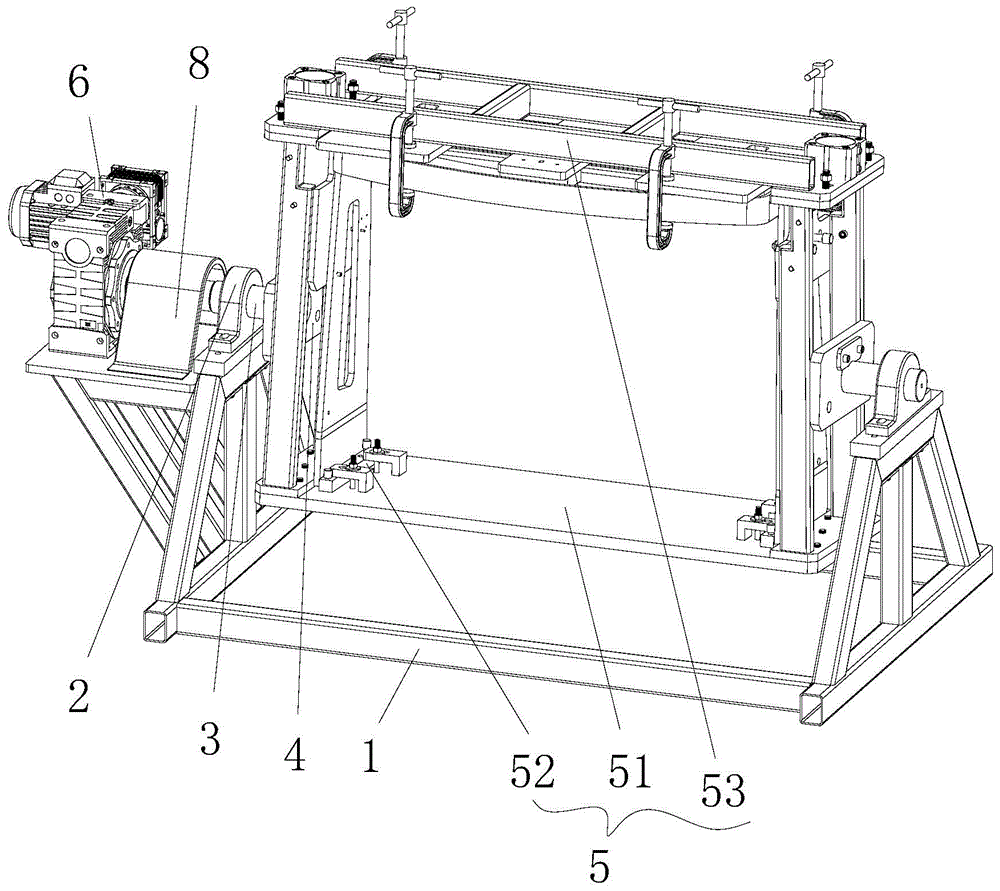
Fig. 1 is a schematic structural view of a novel 360-degree rotary welding tool.
Fig. 2 is a schematic view of a partial structure of a novel 360-degree rotation welding tool.
Fig. 3 is a schematic structural view of a welding tool of a novel 360-degree rotary welding tool.
Fig. 4 is a schematic view of a local structure of a welding tool of a novel 360-degree rotary welding tool.
Detailed Description
The preferred embodiments of the present invention will be described in detail below with reference to the accompanying drawings so that the advantages and features of the invention can be more readily understood by those skilled in the art, and the scope of the invention will be more clearly defined.
Referring to fig. 1 to 4, an embodiment of the present invention includes:
a novel 360-degree rotary welding tool comprises a support 1, bearing seats 2, rotating shafts 3, fixing assemblies 4, welding tools 5, speed reducing motors 6, couplers 7 and a shield 8, wherein the bearing seats 2 are installed on two sides of the upper end of the support 1, the rotating shafts 3 are transversely inserted in the bearing seats 2, the welding tools 5 are installed on the two rotating shafts 3 through the fixing assemblies 4, the speed reducing motors 6 are also installed on the upper end of the support 1, the speed reducing motors 6 are connected with one of the rotating shafts 3 through the couplers 7, the speed reducing motors 6 drive the rotating shafts 3 to rotate, the couplers 7 are located in the shield 8, and the shield 8 is fixed on the support 1; the welding tool 5 comprises a fixed seat 51, vertical plate positioning assemblies 52 and an opening-closing type top plate positioning assembly 53, the vertical plate positioning assemblies 52 are installed on two sides of the fixed seat 51, and the opening-closing type top plate positioning assemblies 53 are installed at the tops of the two vertical plate positioning assemblies 52.
The vertical plate positioning component 52 comprises a support frame 521, a pressure plate 522, a pressure plate bolt 523, a gasket 524, a bottom plate positioning pin 525, a positioning side plate 526, a side plate positioning pin 527 and a locking screw 528, the support frame 521 is vertically fixed on a fixed seat 51, the fixed seat 51 is provided with the pressure plate 522 which is used for compressing the side plate base, the pressure plate bolt 523 passes through the horizontal part of the pressure plate 522 from the bottom of the fixed seat 51, the gasket 524 and a nut are sequentially sleeved on the pressure plate 522 and the pressure plate bolt 523, the fixed seat 51 is also provided with two positioning holes, the bottom plate positioning pin 525 which is used for positioning the side plate base can be inserted in the positioning holes, the support frame 521 is provided with the positioning side plate 526, the positioning side plate 526 is inserted with the side plate positioning pin 527 which is used for positioning the side plate, the upper part of the positioning, the side plates are ensured to be tightly attached to the top plate.
The open-close type top plate positioning component 53 comprises a lower flat plate 531, an upper flat plate 532, an air cylinder 533, guide posts 534, a limiting clamp 535, a steel frame beam 536, a top plate pin 537 and an arc clamp 538, wherein the two lower flat plates 531 are respectively fixed at the upper end of a support frame 521, the upper flat plate 532 is arranged above the lower flat plate 531, the air cylinder 533 is arranged on the two upper flat plates 532, a piston rod of the air cylinder 533 is arranged downwards and is fixedly connected with the lower flat plate 531, the two guide posts 534 are arranged on the lower flat plate 531, the guide posts 534 penetrate through the upper part of the upper flat plate 532 and are provided with the limiting clamp 535, the steel frame beam 536 is fixed between the two upper flat plates 532, a top plate positioning hole is formed in the steel frame beam 536, the top plate pin 537 for positioning the top plate can be.
Fixed subassembly 4 is including supporting otic placode 41 and cardboard 42, axis of rotation 3 is fixed in on supporting otic placode 41, and 3 upper portions of axis of rotation radially are equipped with draw-in groove 30, and draw-in groove 30 department is equipped with cardboard 42, and on cardboard 42 passed through the fix with screw supported otic placode 41, support otic placode 41 was fixed in on the support frame 521 of vertical board locating component 52, draw-in groove 30 and cardboard 42 cooperation avoided axis of rotation 3 and support otic placode 41 to take place relative rotation at the rotation in-process, guarantee axis of rotation 3 and the rotation unanimity of welding frock 5.
When the novel 360-degree rotary welding tool works, firstly, two side plates are clamped, the two side plates are placed on a fixed seat 51, a bottom plate positioning pin 525 is inserted into positioning holes corresponding to a side plate base and the fixed seat 51, a nut on a locking screw 528 is manually rotated until a horizontal plate of a pressure plate 522 tightly presses the side plate base, a side plate positioning pin 527 is inserted into a hole aligned with the side plate, the positioning tool for the two side plates is completed at the moment, then, a top plate is clamped, the top plate is placed below a steel frame cross beam 536, the top plate, the steel frame cross beam 536 and the top plate are fixed through an arch-shaped clamp 538, a top plate pin 537 is inserted into top plate positioning holes of the top plate and the steel frame cross beam 536, the arch-shaped clamp 538 is screwed, the locking screw 528 is adjusted until the side plate is tightly attached to the top plate, the tool for workpieces to be welded is completed at the moment, a speed, and (3) turning off the speed reducing motor 6, welding, continuing to rotate the welding tool 5 after one welding line is finished, turning to a welding angle convenient to weld until all welding lines finish welding, taking down the side plates for positioning after welding is finished, extending the piston rod of the air cylinder 533 to drive the steel frame cross beam 536 to move upwards, driving the whole welding part, namely the top protection frame, to move upwards by the steel frame cross beam 536, and facilitating subsequent hoisting and taking away.
The novel 360-degree rotary welding tool is compact in structure and stable in operation, a top protection frame component can be positioned and clamped, the relative size stability of a top plate and a side plate is guaranteed, the speed reduction motor drives multi-angle welding, the top protection frame component cannot shake, labor intensity is reduced, efficiency is increased, safety guarantee is improved, and the air cylinder is used for compressing and jacking the top surface part of the welding tool and is convenient to disassemble.
The above description is only an embodiment of the present invention, and not intended to limit the scope of the present invention, and all modifications of equivalent structures and equivalent processes performed by the present specification and drawings, or directly or indirectly applied to other related technical fields, are included in the scope of the present invention.