CN113054286A - Battery box device and electric automobile with same - Google Patents

Battery box device and electric automobile with same Download PDF

Info

Publication number
CN113054286A
CN113054286A CN202110334714.6A CN202110334714A CN113054286A CN 113054286 A CN113054286 A CN 113054286A CN 202110334714 A CN202110334714 A CN 202110334714A CN 113054286 A CN113054286 A CN 113054286A
Authority
CN
China
Prior art keywords
air inlet
air
battery box
housing
cooling
Prior art date
Legal status (The legal status is an assumption and is not a legal conclusion. Google has not performed a legal analysis and makes no representation as to the accuracy of the status listed.)
Pending
Application number
CN202110334714.6A
Other languages
Chinese (zh)
Inventor
徐长成
荆振洋
孙丰涛
汪高峰
吴超
江金源
Current Assignee (The listed assignees may be inaccurate. Google has not performed a legal analysis and makes no representation or warranty as to the accuracy of the list.)
Yinlong New Energy Co Ltd
Zhuhai Yinlong Electrical Appliance Co Ltd
Original Assignee
Yinlong New Energy Co Ltd
Zhuhai Yinlong Electrical Appliance Co Ltd
Priority date (The priority date is an assumption and is not a legal conclusion. Google has not performed a legal analysis and makes no representation as to the accuracy of the date listed.)
Filing date
Publication date
Application filed by Yinlong New Energy Co Ltd, Zhuhai Yinlong Electrical Appliance Co Ltd filed Critical Yinlong New Energy Co Ltd
Priority to CN202110334714.6A priority Critical patent/CN113054286A/en
Publication of CN113054286A publication Critical patent/CN113054286A/en
Pending legal-status Critical Current

Links

Images

Classifications

    • H—ELECTRICITY
    • H01—ELECTRIC ELEMENTS
    • H01M—PROCESSES OR MEANS, e.g. BATTERIES, FOR THE DIRECT CONVERSION OF CHEMICAL ENERGY INTO ELECTRICAL ENERGY
    • H01M10/00—Secondary cells; Manufacture thereof
    • H01M10/60—Heating or cooling; Temperature control
    • H01M10/61—Types of temperature control
    • H01M10/613—Cooling or keeping cold
    • B—PERFORMING OPERATIONS; TRANSPORTING
    • B60—VEHICLES IN GENERAL
    • B60L—PROPULSION OF ELECTRICALLY-PROPELLED VEHICLES; SUPPLYING ELECTRIC POWER FOR AUXILIARY EQUIPMENT OF ELECTRICALLY-PROPELLED VEHICLES; ELECTRODYNAMIC BRAKE SYSTEMS FOR VEHICLES IN GENERAL; MAGNETIC SUSPENSION OR LEVITATION FOR VEHICLES; MONITORING OPERATING VARIABLES OF ELECTRICALLY-PROPELLED VEHICLES; ELECTRIC SAFETY DEVICES FOR ELECTRICALLY-PROPELLED VEHICLES
    • B60L50/00—Electric propulsion with power supplied within the vehicle
    • B60L50/50—Electric propulsion with power supplied within the vehicle using propulsion power supplied by batteries or fuel cells
    • B60L50/60—Electric propulsion with power supplied within the vehicle using propulsion power supplied by batteries or fuel cells using power supplied by batteries
    • B60L50/64—Constructional details of batteries specially adapted for electric vehicles
    • H—ELECTRICITY
    • H01—ELECTRIC ELEMENTS
    • H01M—PROCESSES OR MEANS, e.g. BATTERIES, FOR THE DIRECT CONVERSION OF CHEMICAL ENERGY INTO ELECTRICAL ENERGY
    • H01M10/00—Secondary cells; Manufacture thereof
    • H01M10/60—Heating or cooling; Temperature control
    • H01M10/61—Types of temperature control
    • H01M10/617—Types of temperature control for achieving uniformity or desired distribution of temperature
    • H—ELECTRICITY
    • H01—ELECTRIC ELEMENTS
    • H01M—PROCESSES OR MEANS, e.g. BATTERIES, FOR THE DIRECT CONVERSION OF CHEMICAL ENERGY INTO ELECTRICAL ENERGY
    • H01M10/00—Secondary cells; Manufacture thereof
    • H01M10/60—Heating or cooling; Temperature control
    • H01M10/62—Heating or cooling; Temperature control specially adapted for specific applications
    • H01M10/625—Vehicles
    • H—ELECTRICITY
    • H01—ELECTRIC ELEMENTS
    • H01M—PROCESSES OR MEANS, e.g. BATTERIES, FOR THE DIRECT CONVERSION OF CHEMICAL ENERGY INTO ELECTRICAL ENERGY
    • H01M10/00—Secondary cells; Manufacture thereof
    • H01M10/60—Heating or cooling; Temperature control
    • H01M10/65—Means for temperature control structurally associated with the cells
    • H01M10/656—Means for temperature control structurally associated with the cells characterised by the type of heat-exchange fluid
    • H01M10/6561—Gases
    • H01M10/6563—Gases with forced flow, e.g. by blowers
    • Y—GENERAL TAGGING OF NEW TECHNOLOGICAL DEVELOPMENTS; GENERAL TAGGING OF CROSS-SECTIONAL TECHNOLOGIES SPANNING OVER SEVERAL SECTIONS OF THE IPC; TECHNICAL SUBJECTS COVERED BY FORMER USPC CROSS-REFERENCE ART COLLECTIONS [XRACs] AND DIGESTS
    • Y02—TECHNOLOGIES OR APPLICATIONS FOR MITIGATION OR ADAPTATION AGAINST CLIMATE CHANGE
    • Y02E—REDUCTION OF GREENHOUSE GAS [GHG] EMISSIONS, RELATED TO ENERGY GENERATION, TRANSMISSION OR DISTRIBUTION
    • Y02E60/00—Enabling technologies; Technologies with a potential or indirect contribution to GHG emissions mitigation
    • Y02E60/10—Energy storage using batteries
    • Y—GENERAL TAGGING OF NEW TECHNOLOGICAL DEVELOPMENTS; GENERAL TAGGING OF CROSS-SECTIONAL TECHNOLOGIES SPANNING OVER SEVERAL SECTIONS OF THE IPC; TECHNICAL SUBJECTS COVERED BY FORMER USPC CROSS-REFERENCE ART COLLECTIONS [XRACs] AND DIGESTS
    • Y02—TECHNOLOGIES OR APPLICATIONS FOR MITIGATION OR ADAPTATION AGAINST CLIMATE CHANGE
    • Y02T—CLIMATE CHANGE MITIGATION TECHNOLOGIES RELATED TO TRANSPORTATION
    • Y02T10/00—Road transport of goods or passengers
    • Y02T10/60—Other road transportation technologies with climate change mitigation effect
    • Y02T10/70—Energy storage systems for electromobility, e.g. batteries
    • Y—GENERAL TAGGING OF NEW TECHNOLOGICAL DEVELOPMENTS; GENERAL TAGGING OF CROSS-SECTIONAL TECHNOLOGIES SPANNING OVER SEVERAL SECTIONS OF THE IPC; TECHNICAL SUBJECTS COVERED BY FORMER USPC CROSS-REFERENCE ART COLLECTIONS [XRACs] AND DIGESTS
    • Y02—TECHNOLOGIES OR APPLICATIONS FOR MITIGATION OR ADAPTATION AGAINST CLIMATE CHANGE
    • Y02T—CLIMATE CHANGE MITIGATION TECHNOLOGIES RELATED TO TRANSPORTATION
    • Y02T90/00—Enabling technologies or technologies with a potential or indirect contribution to GHG emissions mitigation
    • Y02T90/10—Technologies relating to charging of electric vehicles
    • Y02T90/16—Information or communication technologies improving the operation of electric vehicles

Landscapes

  • Engineering & Computer Science (AREA)
  • Manufacturing & Machinery (AREA)
  • Chemical & Material Sciences (AREA)
  • Chemical Kinetics & Catalysis (AREA)
  • Electrochemistry (AREA)
  • General Chemical & Material Sciences (AREA)
  • Life Sciences & Earth Sciences (AREA)
  • Sustainable Development (AREA)
  • Sustainable Energy (AREA)
  • Power Engineering (AREA)
  • Transportation (AREA)
  • Mechanical Engineering (AREA)
  • Secondary Cells (AREA)
  • Battery Mounting, Suspending (AREA)

Abstract

本发明提供了一种电池箱装置及具有其的电动汽车。电池箱装置包括壳体,壳体具有容纳腔;电池模组设置于容纳腔内,容纳腔的侧壁上开设有第一进风口和出风口,容纳腔的顶部设置有第二进风口,电池模组的外表面与容纳腔的侧壁之间形成第一冷却通道和第二冷却通道,第一冷却通道的进口端与第一进风口连通,第二冷却通道的进口端与第二进风口连通;风机部与壳体连接,风机部用于将壳体外的气流通过第一进风口和第二进风口引入壳体内与电池模组进行热交换后,通过出风口排出壳体外。采用本申请的技术方案,使得电池模组的温度始终处于均衡状态,有效地避免了电池模组的温度出现温差的情况。采用本申请的电池箱装置的结构简单、可靠。
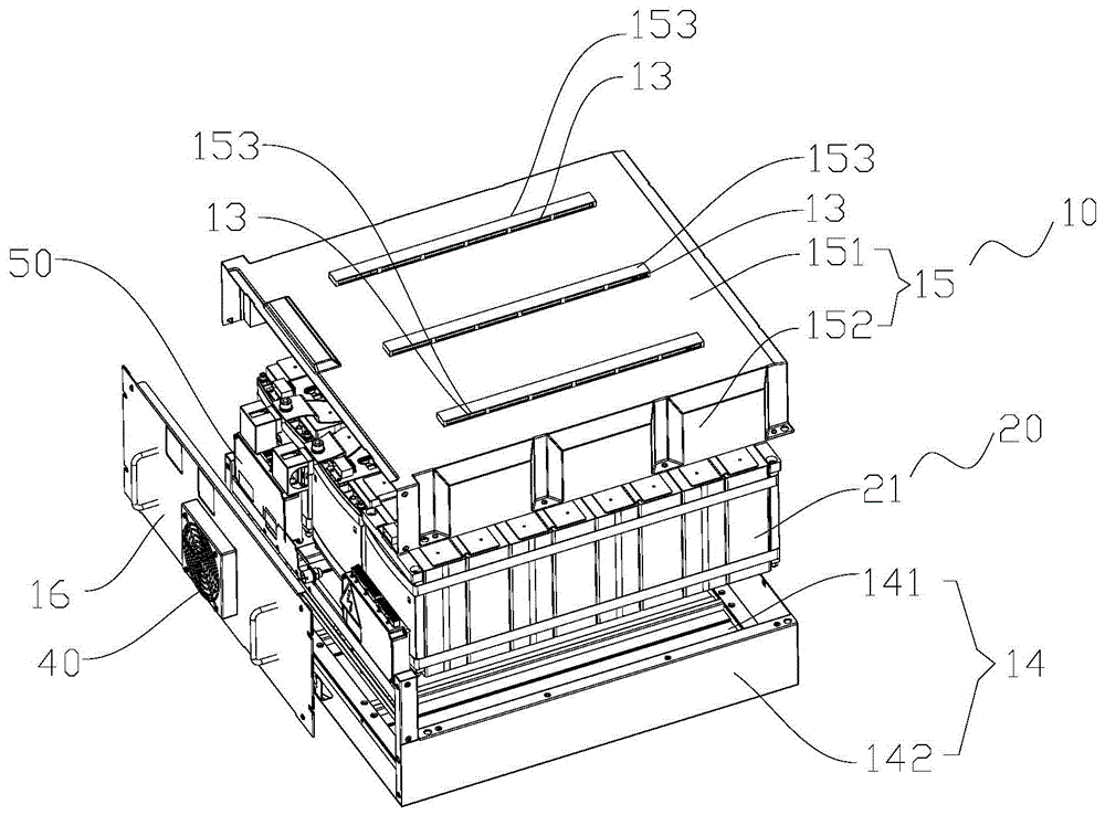
Figure 202110334714

The present invention provides a battery box device and an electric vehicle having the same. The battery box device includes a casing, the casing has an accommodating cavity; the battery module is arranged in the accommodating cavity, the side wall of the accommodating cavity is provided with a first air inlet and an air outlet, the top of the accommodating cavity is provided with a second air inlet, and the battery A first cooling channel and a second cooling channel are formed between the outer surface of the module and the side wall of the accommodating cavity, the inlet end of the first cooling channel is communicated with the first air inlet, and the inlet end of the second cooling channel is connected with the second air inlet The fan part is connected with the casing, and the fan part is used to introduce the air flow outside the casing into the casing through the first air inlet and the second air inlet for heat exchange with the battery module, and then out of the casing through the air outlet. By adopting the technical solution of the present application, the temperature of the battery module is always in a balanced state, and the temperature difference of the temperature of the battery module is effectively avoided. The structure of the battery box device of the present application is simple and reliable.

Figure 202110334714

Description

Battery box device and electric automobile with same
Technical Field
The invention relates to the technical field of electric automobile equipment, in particular to a battery box device and an electric automobile with the same.
Background
The air cooling is one of the common cooling modes of the power battery box, the cooling effect is between natural cooling and liquid cooling, and the cooling device is suitable for the battery box with less electric quantity and low charging and discharging multiplying power; compared with liquid cooling, the liquid cooling system has the main advantages of simple structure configuration, light system weight, low process cost and no liquid leakage risk. However, due to the inherent defects of small air density and low heat conductivity coefficient, the heat absorption is easy to reach saturation during convection heat exchange, and the heat dissipation of the cell on the leeward side of the module is easy to be insufficient due to the series heat dissipation of the long module, so that the temperature difference between the cell on the windward side and the cell on the leeward side is large.
Disclosure of Invention
The invention mainly aims to provide a battery box device and an electric automobile with the same, and aims to solve the problem that the temperature difference between a windward side cell and a leeward side cell of a cell assembly in the prior art is large.
In order to achieve the above object, according to one aspect of the present invention, there is provided a battery case device including: a housing having an accommodating chamber; the battery module is arranged in the accommodating cavity, a first air inlet and an air outlet are formed in the side wall of the accommodating cavity, a second air inlet is formed in the top of the accommodating cavity, a first cooling channel and a second cooling channel are formed between the outer surface of the battery module and the side wall of the accommodating cavity, the inlet end of the first cooling channel is communicated with the first air inlet, and the inlet end of the second cooling channel is communicated with the second air inlet; and the fan part is used for introducing airflow outside the shell into the shell through the first air inlet and the second air inlet, performing heat exchange with the battery module in the shell, and discharging the airflow out of the shell through the air outlet.
Further, the first cooling channel and the second cooling channel are independently arranged, the outlet end of the first cooling channel is communicated with the air outlet, and the outlet end of the second cooling channel is communicated with the air outlet.
Further, the first cooling passage and the second cooling passage are provided in communication.
Further, the housing includes: the bottom shell is provided with a bottom plate and a first enclosing plate, the first enclosing plate is arranged along the circumferential direction of the bottom plate, a first air inlet is formed in the first enclosing plate, and a first cooling channel is formed between the bottom of the battery module and the bottom plate as well as between the bottom of the battery module and the first enclosing plate.
Further, the housing further includes: the upper cover, the upper cover has roof and second bounding wall, and the second bounding wall extends the setting along the circumference of roof, and the drain pan encloses with the upper cover and establishes into and hold the chamber, is provided with the second air intake on the roof, between the top of battery module and the internal surface of roof to and form second cooling channel between the outer peripheral face of battery module and the second bounding wall.
Further, the first cooling channel extends along the length direction of the bottom shell, and the second cooling channel extends along the height direction of the bottom shell.
Furthermore, the top of the upper cover is provided with a protruding structure, at least one side wall of the protruding structure is provided with a second air inlet, and air flow enters the shell from the second air inlet along the horizontal direction.
Furthermore, the number of the second air inlets is multiple, and the multiple second air inlets are arranged at intervals along the length direction of the protruding structure.
Further, the protruding structures are multiple, and the multiple protruding structures are arranged at intervals along the width direction of the upper cover.
Furthermore, the first air inlets are multiple, and the multiple first air inlets are arranged at intervals along the width direction of the shell.
Furthermore, the number of the first cooling channels is multiple, the multiple first cooling channels are arranged in one-to-one correspondence with the multiple first air inlets, and the overflow volume of at least one of the multiple first cooling channels is set differently from the overflow volume of the rest of the first cooling channels.
Further, the number of the second cooling channels is four, and the ratio of the overflow of the four second cooling channels in the width direction of the shell is as follows: q1: q2: q3: q4 ═ 1:2:2: 1.
Further, the housing further includes: the installation curb plate, the installation curb plate is connected with drain pan and upper cover, and fan portion is connected with the installation curb plate, and the air outlet has been seted up to the installation curb plate, and first air intake is seted up on the lateral wall that sets up with the installation curb plate of drain pan relatively.
Further, battery module includes a plurality of electric core subassemblies, and a plurality of electric core subassemblies set up along the width direction interval of casing, and the roof department relative with each electric core subassembly of casing all is provided with a second air intake.
Further, the air flow entering the housing from the second air inlet may flow into the second cooling passage along at least one outer side of the electric core assembly after being blown toward the top of the electric core assembly, or may flow to the air outlet along at least one outer side of the electric core assembly after being blown toward the top of the electric core assembly to be discharged outside the housing.
Further, the fan portion includes an axial fan.
In order to achieve the above object, according to one aspect of the present invention, there is provided an electric vehicle including a battery box apparatus, the battery box apparatus being the above battery box apparatus.
By applying the technical scheme of the invention, the first cooling channel and the second cooling channel are arranged between the shell and the battery module, and the first air inlet and the second air inlet are respectively arranged on the side wall and the top of the accommodating cavity of the shell, so that when the fan part works, external air flow is introduced into the first cooling channel and the second cooling channel through the first air inlet and the second air inlet to cool the battery module, the temperature of the battery module is always in a balanced state, and the temperature difference of the battery module is effectively avoided. Adopt the simple structure of the battery box device of this application, reliable.
Drawings
The accompanying drawings, which are incorporated in and constitute a part of this application, illustrate embodiments of the invention and, together with the description, serve to explain the invention and not to limit the invention. In the drawings:
fig. 1 shows an exploded schematic view of a first embodiment of a battery case assembly according to the present invention;
fig. 2 shows an exploded view of a second embodiment of a battery case assembly according to the present invention;
fig. 3 shows a schematic configuration of a third embodiment of the battery case device according to the present invention.
Wherein the figures include the following reference numerals:
10. a housing; 11. a first air inlet; 12. an air outlet; 13. a second air inlet;
14. a bottom case; 141. a base plate; 142. a first enclosing plate;
15. an upper cover; 151. a top plate; 152. a second enclosing plate; 153. a raised structure;
16. installing a side plate;
20. a battery module; 21. an electrical core assembly;
31. a first cooling channel; 32. a second cooling channel;
40. a fan section;
50. a BMS system;
A. a temperature sensing area.
Detailed Description
It should be noted that the embodiments and features of the embodiments in the present application may be combined with each other without conflict. The present invention will be described in detail below with reference to the embodiments with reference to the attached drawings.
It is noted that the terminology used herein is for the purpose of describing particular embodiments only and is not intended to be limiting of example embodiments according to the present application. As used herein, the singular forms "a", "an" and "the" are intended to include the plural forms as well, and it should be understood that when the terms "comprises" and/or "comprising" are used in this specification, they specify the presence of stated features, steps, operations, devices, components, and/or combinations thereof, unless the context clearly indicates otherwise.
It should be noted that the terms "first," "second," and the like in the description and claims of this application and in the drawings described above are used for distinguishing between similar elements and not necessarily for describing a particular sequential or chronological order. It is to be understood that the terms so used are interchangeable under appropriate circumstances such that the embodiments of the application described herein are, for example, capable of operation in sequences other than those illustrated or otherwise described herein. Furthermore, the terms "comprises," "comprising," and "having," and any variations thereof, are intended to cover a non-exclusive inclusion, such that a process, method, system, article, or apparatus that comprises a list of steps or elements is not necessarily limited to those steps or elements expressly listed, but may include other steps or elements not expressly listed or inherent to such process, method, article, or apparatus.
Exemplary embodiments according to the present application will now be described in more detail with reference to the accompanying drawings. These exemplary embodiments may, however, be embodied in many different forms and should not be construed as limited to only the embodiments set forth herein. It is to be understood that these embodiments are provided so that this disclosure will be thorough and complete, and will fully convey the concept of the exemplary embodiments to those skilled in the art, in the drawings, it is possible to enlarge the thicknesses of layers and regions for clarity, and the same devices are denoted by the same reference numerals, and thus the description thereof will be omitted.
Referring to fig. 1 to 3, according to an embodiment of the present application, a battery case apparatus is provided.
Specifically, the battery box device includes a case 10 and a battery module 20. The housing 10 has a receiving cavity. The battery module 20 is disposed in the accommodating cavity. The side wall of the accommodating cavity is provided with a first air inlet 11 and an air outlet 12. The top of the accommodating cavity is provided with a second air inlet 13. A first cooling channel 31 and a second cooling channel 32 are formed between the outer surface of the battery module 20 and the side wall of the receiving cavity. The inlet end of the first cooling passage 31 is communicated with the first inlet port 11, and the inlet end of the second cooling passage 32 is communicated with the second inlet port 13. The fan portion 40 is connected to the housing 10, and the fan portion 40 is configured to introduce the airflow outside the housing 10 into the housing 10 through the first air inlet 11 and the second air inlet 13 to exchange heat with the battery module 20, and then discharge the airflow outside the housing 10 through the air outlet 12.
By adopting the technical scheme of the invention, the first cooling channel 31 and the second cooling channel 32 are arranged between the shell 10 and the battery module 20, and the first air inlet 11 and the second air inlet 13 are respectively arranged on the side wall and the top of the accommodating cavity of the shell, so that when the fan part operates, external air flow is introduced into the first cooling channel 31 and the second cooling channel 32 through the first air inlet 11 and the second air inlet 13 to cool the battery module 20, the temperature of the battery module 20 is always in a balanced state, and the condition that the temperature of the battery module 20 has a temperature difference is effectively avoided. Adopt the simple structure of the battery box device of this application, reliable.
Specifically, the first cooling channel 31 and the second cooling channel 32 are independently disposed, an outlet end of the first cooling channel 31 is disposed to communicate with the air outlet 12, and an outlet end of the second cooling channel 32 is disposed to communicate with the air outlet 12. Set up like this and can improve cooling efficiency, realize battery module 20 and all can carry out the heat exchange with the air current at height and length direction to guarantee that battery module 20's whole all is in the same temperature level, avoid battery module 20 to appear the condition that local temperature is on the high side, adopt the technical scheme of this application to prolong battery module 20's life effectively.
Specifically, the first cooling passage 31 and the second cooling passage 32 are provided in communication. The arrangement enables the air flows entering from the first air inlet 11 and the second air inlet 13 to be converged, so that the temperature consistency of the battery module 20 in the length direction, the height direction and the width direction is improved, and the temperature difference of the battery pack assembly 21 is minimized as a whole.
As shown in fig. 2, the housing 10 includes a bottom case 14. The bottom case 14 has a bottom plate 141 and a first enclosure 142. The first enclosure 142 is disposed along the circumferential direction of the bottom plate 141, the first air inlet 11 is formed in the first enclosure 142, and a first cooling channel 31 is formed between the bottom of the battery module 20 and the bottom plate 141 and the first enclosure 142. Set up like this and make first air intake 11 form with battery module 20's bottom, can play the effect of effectively cooling down battery module 20's bottom.
Further, the housing 10 further includes an upper cover 15. The upper cover 15 has a top plate 151 and a second enclosing plate 152, the second enclosing plate 152 extends along the circumference of the top plate 151, the bottom case 14 and the upper cover 15 are enclosed to form an accommodating cavity, the top plate 151 is provided with a second air inlet 13, and a second cooling channel 32 is formed between the top of the battery module 20 and the inner surface of the top plate 151, and between the outer circumferential surface of the battery module 20 and the second enclosing plate 152. The arrangement enables the air flow entering from the second air inlet 13 to be directly blown to the top of the battery module 20, and the effect of effectively reducing the temperature of the top of the battery module 20 is achieved.
Further, in order to keep the temperature of the battery module 20 uniform in the length and height directions, the first cooling channel 31 is provided to extend in the length direction of the bottom case 14, and the second cooling channel 32 is provided to extend in the height direction of the bottom case 14.
In the present application, the top of the upper cover 15 is provided with a protrusion structure 153. At least one side wall of the protrusion 153 is opened with a second air inlet 13, and the air flow enters the housing 10 from the second air inlet 13 along the horizontal direction. This arrangement can prevent foreign matter outside the case 10 from entering the case 10 to cause a short circuit of the battery module 20.
Further, the number of the second air inlets 13 is plural, and the plural second air inlets 13 are arranged at intervals along the length direction of the convex structure 153. Set up like this and can make second air intake 13 arrange along battery module 20's length direction, improved battery module 20 at length direction's intake, then improved battery module 20's cooling efficiency.
As shown in fig. 1, in order to further improve the heat exchange efficiency of the battery module 20, the protrusion structures 153 are provided in plurality, and the plurality of protrusion structures 153 are provided at intervals in the width direction of the upper cover 15. Also, the plurality of second air inlets 13 are provided at intervals along the length direction of the convex structure 153. This arrangement can make the distribution of the second air inlets 13 more uniform, and the air circulation in the battery module 20 is more efficient.
As shown in fig. 2, the first air inlet 11 is plural, and the plural first air inlets 11 are arranged at intervals along the width direction of the housing 10. The arrangement can improve the air intake from one side of the bottom of the battery module 20, and effectively ensures the heat exchange efficiency of one side of the bottom of the battery module 20.
Specifically, in order to further improve the reliability of the battery box device, the first cooling passages 31 are provided in plurality, the plurality of first cooling passages 31 are provided in one-to-one correspondence with the plurality of first air inlets 11, and an excess flow rate of at least one first cooling passage 31 among the plurality of first cooling passages 31 is set differently from excess flow rates of the remaining first cooling passages 31. In the present embodiment, the plurality of first cooling passages 31 and the plurality of first air inlets 11 are arranged in a one-to-one correspondence to form an airflow passage structure. In the present embodiment, the first air flow channel structure is composed of a plurality of first cooling channels 31, a plurality of first air inlets 11 and a plurality of air outlets 12, so that the temperature difference of the battery module 20 in the length direction can be controlled. Also, the amount of the over-flow of the cooling passage may be set according to the specific position of the cooling passage in the housing 10, i.e., the size of the cross-sectional area of the cooling passage may be changed according to the position of the cooling passage. In general, the cross section of the cooling passage located outside the housing may be set smaller, and the cross section of the cooling passage located at the middle of the housing may be set larger.
As shown in fig. 3, the number of the second cooling passages 32 is four, and the ratio of the excess flow rate of the four second cooling passages 32 in the width direction of the casing 10 is: q1: q2: q3: q4 ═ 1:2:2: 1. In this embodiment, set up like this and can guarantee that the wind channel flow resistance is the same basically, and make along the heat exchange efficiency of battery module 20's direction of height keep same horizontality, guaranteed that battery module 20 is in all the time and carries out the operation under the same temperature state.
Further, the housing 10 also includes a mounting side plate 16. The mounting side plate 16 is connected with the bottom shell 14 and the upper cover 15, the fan portion 40 is connected with the mounting side plate 16, the mounting side plate 16 is provided with an air outlet 12, and the first air inlet 11 is formed in the side wall of the bottom shell 14, which is opposite to the mounting side plate 16. In the technical scheme who adopts this application, the battery module 20 is firm in structure on the whole to installation curb plate 16 and the connection setting of drain pan 14 and upper cover 15, forms the basic frame of battery module 20. Through rationally setting up the position of fan portion 40, air outlet 12 and first air intake 11, can be so that the air current circulation among the series-parallel connection heat radiation structure of battery module 20 is more high-efficient, arranges more rationally, and its overall structure size can reduce.
As shown in fig. 1, the battery module 20 includes a plurality of cell assemblies 21. A plurality of electric core assemblies 21 are arranged at intervals along the width direction of the housing 10, and a second air inlet 13 is arranged at the top wall of the housing 10 opposite to each electric core assembly 21. This arrangement can improve the heat dissipation efficiency of the battery module 20. The battery module 20 can reduce the temperature difference in the width direction by properly arranging the position of the second air inlet 13.
Specifically, the airflow entering the housing 10 from the second air inlet 13 flows into the second cooling passage 32 along at least one outer side of the electric core module 21 after being blown toward the top of the electric core module 21, or flows into the air outlet 12 along at least one outer side of the electric core module 21 after being blown toward the top of the electric core module 21 from the second air inlet 13 to be discharged outside the housing 10. The arrangement enables the temperature difference between the windward side and the leeward side of the battery module 20 to be controlled, and the temperature difference between the top of the battery module 20 and the length direction to be controlled.
The fan part 40 comprises an axial flow fan, and by adopting the arrangement scheme, the air inlet efficiency of the first air inlet 11 and the second air inlet 13 can be improved.
The battery box device in the above embodiment may also be used in the technical field of electric vehicle equipment, that is, according to another aspect of the present application, there is provided an electric vehicle, including the battery box device, where the battery box device is the battery box device in the above embodiment.
Specifically, in this application, through set up the air intake of equidirectional at the bottom and the top of casing, can guarantee that battery module 20 is in the same level all the time at height, length and width direction's difference in temperature. To long module battery box, change single side series connection air inlet into the mixed connection air inlet of multilateral to the parallelly connected air inlet in top cools off single electric core as giving first place to, and electric core subassembly 21 bottom adopts side bottom air inlet series connection cooling, and through the excessive flow of reasonable adjustment top and side air intake position and cooling channel, it is minimum to make the difference in temperature between electric core subassembly 21, reaches extension battery package cycle life's effect.
The top of the electric core assembly 21 adopts a plurality of air inlets to simultaneously supply air so as to cool the electric core, and the temperature consistency of the electric core assembly 21 in the length direction and the width direction is realized. For the temperature difference of the electric core assembly 21 in the height direction, the design of arranging the first air inlet 11 on the first enclosing plate 142 is adopted, so that the cooling of the bottom of the electric core assembly 21 is enhanced, and the consistency of the height temperature of the battery module 20 is realized; the air inlet volume of the first air inlet 11 and the second air inlet 13 should be adjusted to achieve the optimal ratio according to the actual situation. Wherein the intake air volume is related to the flow volume of the cooling channels (the first cooling channel 31, the second cooling channel 32).
Second air intake 13 is located upper cover 15 top, and is located electric core subassembly 21 directly over, from 2 nd electric core of module to 2 nd electric core subassembly 21 lateral surface and air convection heat transfer from last, leads to outside electric core temperature generally lower, and the wind gap length and width can be adjusted according to the reality. The second air inlet 13 at the top of the upper cover 15 adopts a side air duct structure design to prevent foreign objects from falling into the housing 10 to cause short circuit of the electric core assembly 21. The airflow entering the first air inlet 11 is mainly used for cooling the bottom of the electric core assembly 21. The ratio of the excess flow rate of the four second cooling passages 32 in the width direction of the casing 10 is: q1: q2: q3: q4 is 1:2:2:1 to ensure that the duct flow resistance is substantially the same. The control strategy of the axial flow fan embedded in the BMS system 50 can regulate and control the axial flow fan based on the sampling stability and classification of the electric core assembly 21.
Specifically, the battery module 20 in the battery box is subjected to bidirectional convective heat transfer in the height and length directions. Wherein, the second air intake 13 at the top of upper cover 15 is located directly over battery module 21, and except battery module 20 both sides electricity core (both sides electricity core surface has certain convection heat dissipation through contact end plate and air), second air intake 13 becomes the one-to-one relation with electric core (an electricity core corresponds and is provided with a second air intake 13 promptly), mainly used for parallelly connected cooling of battery module 21, guarantees the uniformity of battery module 21 temperature in width, thickness direction. The cell assembly 21 is a combination of a plurality of cells. The first air inlet 11 is located below the housing and is mainly used for cooling the bottom of the battery module 20 and the length direction of the battery module 20.
The working process of the air-cooled series-parallel heat dissipation structure of the power battery box is as follows:
1. the battery pack is powered up and the BMS system 50 self-checks.
2. The BMS system 50 detects the temperature of the temperature detection area a of the electric core assembly 21.
3. When the temperature of the temperature detection area A is higher than the preset temperature of the BMS system 50, the axial flow fan is started, the air cooling system starts to work, along with the rising or falling of the temperature of the electric core assembly 21, the BMS system 50 adjusts the rotating speed of the fan in real time by controlling the current of the axial flow fan, further controls the flow of the fan, and realizes the adjustment of the highest temperature and the temperature rise rate of the electric core assembly 21.
4. The battery package is down electrified, and BMS system 50 detects electric core temperature detection area A temperature, and when temperature detection area A temperature was less than the preset temperature of BMS system 50, the fan was closed. The BMS system 50 is internally provided with a fan control strategy based on the temperature of the electric core assembly 21, and the axial flow fan is regulated and controlled according to the sampling temperature, the temperature rise rate and the like of the electric core assembly 21.
Spatially relative terms, such as "above … …," "above … …," "above … …," "above," and the like, may be used herein for ease of description to describe one device or feature's spatial relationship to another device or feature as illustrated in the figures. It will be understood that the spatially relative terms are intended to encompass different orientations of the device in use or operation in addition to the orientation depicted in the figures. For example, if a device in the figures is turned over, devices described as "above" or "on" other devices or configurations would then be oriented "below" or "under" the other devices or configurations. Thus, the exemplary term "above … …" can include both an orientation of "above … …" and "below … …". The device may be otherwise variously oriented (rotated 90 degrees or at other orientations) and the spatially relative descriptors used herein interpreted accordingly.
In addition to the foregoing, it should be noted that reference throughout this specification to "one embodiment," "another embodiment," "an embodiment," or the like, means that a particular feature, structure, or characteristic described in connection with the embodiment is included in at least one embodiment described generally throughout this application. The appearances of the same phrase in various places in the specification are not necessarily all referring to the same embodiment. Further, when a particular feature, structure, or characteristic is described in connection with any embodiment, it is submitted that it is within the scope of the invention to effect such feature, structure, or characteristic in connection with other embodiments.
In the foregoing embodiments, the descriptions of the respective embodiments have respective emphasis, and for parts that are not described in detail in a certain embodiment, reference may be made to related descriptions of other embodiments.
The above description is only a preferred embodiment of the present invention and is not intended to limit the present invention, and various modifications and changes may be made by those skilled in the art. Any modification, equivalent replacement, or improvement made within the spirit and principle of the present invention should be included in the protection scope of the present invention.

Claims (17)

1. A battery case apparatus, comprising:
a housing (10), the housing (10) having a receiving cavity;
the battery module (20) is arranged in the accommodating cavity, a first air inlet (11) and an air outlet (12) are formed in the side wall of the accommodating cavity, a second air inlet (13) is formed in the top of the accommodating cavity, a first cooling channel (31) and a second cooling channel (32) are formed between the outer surface of the battery module (20) and the side wall of the accommodating cavity, the inlet end of the first cooling channel (31) is communicated with the first air inlet (11), and the inlet end of the second cooling channel (32) is communicated with the second air inlet (13);
the air conditioner comprises a fan portion (40), the fan portion (40) is connected with the shell (10), the fan portion (40) is used for enabling air flow outside the shell (10) to pass through a first air inlet (11) and a second air inlet (13) to be introduced into the shell (10) and the battery module (20) to be subjected to heat exchange, and then the air outlet (12) is discharged outside the shell (10).
2. The battery box device according to claim 1, wherein the first cooling passage (31) and the second cooling passage (32) are independently provided, an outlet end of the first cooling passage (31) is provided in communication with the air outlet (12), and an outlet end of the second cooling passage (32) is provided in communication with the air outlet (12).
3. The battery box device according to claim 1, wherein the first cooling passage (31) and the second cooling passage (32) are provided in communication.
4. The battery box device according to any one of claims 1 to 3, wherein the housing (10) includes:
the bottom shell (14) is provided with a bottom plate (141) and a first enclosing plate (142), the first enclosing plate (142) is arranged along the circumferential direction of the bottom plate (141), the first air inlet (11) is formed in the first enclosing plate (142), and a first cooling channel (31) is formed between the bottom of the battery module (20) and the bottom plate (141) and the first enclosing plate (142).
5. The battery box assembly of claim 4, wherein the housing (10) further comprises:
the upper cover (15), the upper cover (15) has roof (151) and second bounding wall (152), second bounding wall (152) are followed the circumference of roof (151) extends the setting, drain pan (14) with upper cover (15) enclose and establish into hold the chamber, be provided with on roof (151) second air intake (13), between the top of battery module (20) and the internal surface of roof (151), and form between the outer peripheral face of battery module (20) and second bounding wall (152) second cooling channel (32).
6. The battery box device according to claim 5, wherein the first cooling channel (31) extends along a length direction of the bottom case (14), and the second cooling channel (32) extends along a height direction of the bottom case (14).
7. The battery box device according to claim 5, wherein a protruding structure (153) is disposed on the top of the upper cover (15), at least one side wall of the protruding structure (153) is opened with the second air inlet (13), and the air flow enters the housing (10) from the second air inlet (13) along the horizontal direction.
8. The battery box assembly of claim 7, wherein the second air inlet (13) is plural, and the plural second air inlets (13) are arranged at intervals along the length direction of the protruding structure (153).
9. The battery box device according to claim 7, wherein the plurality of the convex structures (153) are provided, and the plurality of the convex structures (153) are provided at intervals in a width direction of the upper cover (15).
10. The battery box device according to claim 1, wherein the first air inlet opening (11) is plural, and the plural first air inlet openings (11) are provided at intervals in a width direction of the housing (10).
11. The battery box device according to claim 10, wherein the first cooling passages (31) are plural, the plural first cooling passages (31) are provided in one-to-one correspondence with the plural first air inlets (11), and an excess flow rate of at least one of the first cooling passages (31) among the plural first cooling passages (31) is set differently from that of the remaining first cooling passages (31).
12. The battery box device according to claim 11, wherein the number of the second cooling passages (32) is four, and the ratio of the excessive flow rate of the four second cooling passages (32) in the width direction of the housing (10) is: q1: q2: q3: q4 ═ 1:2:2: 1.
13. The battery box assembly of claim 5, wherein the housing (10) further comprises:
the air conditioner comprises an installation side plate (16), the installation side plate (16) is connected with the bottom shell (14) and the upper cover (15), the fan portion (40) is connected with the installation side plate (16), the installation side plate (16) is provided with the air outlet (12), and the first air inlet (11) is formed in the side wall, opposite to the installation side plate (16), of the bottom shell (14).
14. The battery box device according to claim 1, wherein the battery module (20) includes a plurality of battery cell assemblies (21), the plurality of battery cell assemblies (21) are arranged at intervals in a width direction of the housing (10), and one second air inlet (13) is provided at a top wall of the housing (10) opposite to each of the battery cell assemblies (21).
15. The battery box device according to claim 14, wherein the air flow entering the housing (10) from the second air intake opening (13) flows along at least one outer side of the electric core assembly (21) into the second cooling passage (32) after being blown toward the top of the electric core assembly (21), or the air flow entering the housing (10) from the second air intake opening (13) flows along at least one outer side of the electric core assembly (21) to the air outlet opening (12) to be discharged outside the housing (10) after being blown toward the top of the electric core assembly (21).
16. The battery box device according to claim 1, wherein the fan portion (40) comprises an axial fan.
17. An electric vehicle comprising a battery box assembly, wherein the battery box assembly is as claimed in any one of claims 1 to 16.
CN202110334714.6A 2021-03-29 2021-03-29 Battery box device and electric automobile with same Pending CN113054286A (en)

Priority Applications (1)

Application Number Priority Date Filing Date Title
CN202110334714.6A CN113054286A (en) 2021-03-29 2021-03-29 Battery box device and electric automobile with same

Applications Claiming Priority (1)

Application Number Priority Date Filing Date Title
CN202110334714.6A CN113054286A (en) 2021-03-29 2021-03-29 Battery box device and electric automobile with same

Publications (1)

Publication Number Publication Date
CN113054286A true CN113054286A (en) 2021-06-29

Family

ID=76516036

Family Applications (1)

Application Number Title Priority Date Filing Date
CN202110334714.6A Pending CN113054286A (en) 2021-03-29 2021-03-29 Battery box device and electric automobile with same

Country Status (1)

Country Link
CN (1) CN113054286A (en)

Cited By (7)

* Cited by examiner, † Cited by third party
Publication number Priority date Publication date Assignee Title
CN113594598A (en) * 2021-07-29 2021-11-02 中国第一汽车股份有限公司 Battery module and battery pack
CN114069126A (en) * 2021-11-22 2022-02-18 东莞新能安科技有限公司 Battery pack, battery pack system and electric equipment
CN114552089A (en) * 2022-02-21 2022-05-27 三一重工股份有限公司 Battery boxes, stacked battery modules and working machines
CN115425321A (en) * 2022-08-30 2022-12-02 厦门新能达科技有限公司 Battery pack and electric device
CN117673555A (en) * 2023-12-08 2024-03-08 广州明美新能源股份有限公司 Battery pack
CN119890527A (en) * 2025-01-17 2025-04-25 武汉亿纬储能有限公司 Battery pack
WO2026055816A1 (en) * 2024-09-10 2026-03-19 宁德时代新能源科技股份有限公司 Energy storage device and energy storage system

Cited By (10)

* Cited by examiner, † Cited by third party
Publication number Priority date Publication date Assignee Title
CN113594598A (en) * 2021-07-29 2021-11-02 中国第一汽车股份有限公司 Battery module and battery pack
CN113594598B (en) * 2021-07-29 2023-05-12 中国第一汽车股份有限公司 Battery module and battery pack
CN114069126A (en) * 2021-11-22 2022-02-18 东莞新能安科技有限公司 Battery pack, battery pack system and electric equipment
CN114069126B (en) * 2021-11-22 2024-04-30 东莞新能安科技有限公司 Battery packs, battery pack systems and electrical equipment
CN114552089A (en) * 2022-02-21 2022-05-27 三一重工股份有限公司 Battery boxes, stacked battery modules and working machines
CN115425321A (en) * 2022-08-30 2022-12-02 厦门新能达科技有限公司 Battery pack and electric device
WO2024046194A1 (en) * 2022-08-30 2024-03-07 厦门新能达科技有限公司 Battery pack and electric device
CN117673555A (en) * 2023-12-08 2024-03-08 广州明美新能源股份有限公司 Battery pack
WO2026055816A1 (en) * 2024-09-10 2026-03-19 宁德时代新能源科技股份有限公司 Energy storage device and energy storage system
CN119890527A (en) * 2025-01-17 2025-04-25 武汉亿纬储能有限公司 Battery pack

Similar Documents

Publication Publication Date Title
WO2021223106A1 (en) Heat dissipating cabinet and communication device
CN114013312A (en) Charging pile and control method thereof
CN108520932A (en) Battery pack and vehicle with same
KR100669410B1 (en) Battery module
CN113795970A (en) Battery and unmanned aerial vehicle
CN209544558U (en) A battery pack with an air duct structure that enhances active heat dissipation
CN215184186U (en) Battery box device and electric automobile with same
CN115000576A (en) Small energy storage system container
CN101950798B (en) Battery box
CN106654443A (en) Battery box capable of automatically realizing temperature closed-loop control
CN219506251U (en) Unmanned aerial vehicle basic station and unmanned aerial vehicle system
CN218827425U (en) Air-cooled battery box and electronic equipment
CN121528976A (en) A secondary battery charging and discharging device with a uniform temperature air duct system
CN216015561U (en) Laminate polymer battery box and battery module
JP4250785B2 (en) Charger
CN209804729U (en) Heat dissipation device for lead-acid storage battery
CN209312851U (en) Battery cupboard
CN220000770U (en) Structure convenient for smooth flow of aerosol and aerosol generating device
CN218039454U (en) Battery pack and energy storage system
CN216268737U (en) Charging pile
CN215496940U (en) Battery cooling structure and aircraft
CN217009262U (en) Integrated hydrogen energy fuel cell stack structure
CN208208825U (en) Power battery box and cooling device thereof
CN224006398U (en) Heat radiation system of energy storage container and switch box
CN222355207U (en) Air-cooled heat dissipation energy storage battery cabinet and energy storage device

Legal Events

Date Code Title Description
PB01 Publication
PB01 Publication
SE01 Entry into force of request for substantive examination
CB02 Change of applicant information

Country or region after: China

Address after: 519040 area a, No.2 factory building, No.16 Jinhu Road, Sanzao Town, Jinwan District, Zhuhai City, Guangdong Province

Applicant after: Zhuhai Gree titanium Electric Appliance Co.,Ltd.

Applicant after: YINLONG ENERGY Co.,Ltd.

Address before: Zone A, Building 2, No. 16 Jinhu Road, Sanzao Town, Jinwan District, Zhuhai City, Guangdong Province

Applicant before: ZHUHAI YINLONG ELECTRICAL APPLIANCE Co.,Ltd.

Country or region before: China

Applicant before: YINLONG ENERGY Co.,Ltd.

CB02 Change of applicant information

Country or region after: China

Address after: Zone A, Building 2, No. 16 Jinhu Road, Sanzao Town, Jinwan District, Zhuhai City, Guangdong Province

Applicant after: ZHUHAI YINLONG ELECTRICAL APPLIANCE Co.,Ltd.

Applicant after: Gree titanium new energy Co.,Ltd.

Address before: Zone A, Building 2, No. 16 Jinhu Road, Sanzao Town, Jinwan District, Zhuhai City, Guangdong Province

Applicant before: ZHUHAI YINLONG ELECTRICAL APPLIANCE Co.,Ltd.

Country or region before: China

Applicant before: YINLONG ENERGY Co.,Ltd.

CB02 Change of applicant information