CN113045369A - Detonator withdrawal collecting device and method - Google Patents
Detonator withdrawal collecting device and method Download PDFInfo
- Publication number
- CN113045369A CN113045369A CN202110342738.6A CN202110342738A CN113045369A CN 113045369 A CN113045369 A CN 113045369A CN 202110342738 A CN202110342738 A CN 202110342738A CN 113045369 A CN113045369 A CN 113045369A
- Authority
- CN
- China
- Prior art keywords
- detonator
- conveying
- conveying frame
- sleeve
- withdrawal
- Prior art date
- Legal status (The legal status is an assumption and is not a legal conclusion. Google has not performed a legal analysis and makes no representation as to the accuracy of the status listed.)
- Granted
Links
- 238000000034 method Methods 0.000 title abstract description 11
- 230000000149 penetrating effect Effects 0.000 claims abstract description 4
- 238000007789 sealing Methods 0.000 claims description 6
- 230000006835 compression Effects 0.000 claims description 3
- 238000007906 compression Methods 0.000 claims description 3
- 230000000694 effects Effects 0.000 abstract description 5
- 238000004519 manufacturing process Methods 0.000 description 4
- 238000003754 machining Methods 0.000 description 2
- 238000012986 modification Methods 0.000 description 2
- 230000004048 modification Effects 0.000 description 2
- 230000002337 anti-port Effects 0.000 description 1
- 230000009286 beneficial effect Effects 0.000 description 1
- 238000005516 engineering process Methods 0.000 description 1
- 238000004880 explosion Methods 0.000 description 1
- 238000010030 laminating Methods 0.000 description 1
- 230000002045 lasting effect Effects 0.000 description 1
- 230000002441 reversible effect Effects 0.000 description 1
- 230000003068 static effect Effects 0.000 description 1
- 230000001360 synchronised effect Effects 0.000 description 1
Images



Classifications
-
- C—CHEMISTRY; METALLURGY
- C06—EXPLOSIVES; MATCHES
- C06C—DETONATING OR PRIMING DEVICES; FUSES; CHEMICAL LIGHTERS; PYROPHORIC COMPOSITIONS
- C06C7/00—Non-electric detonators; Blasting caps; Primers
- C06C7/02—Manufacture; Packing
Landscapes
- Engineering & Computer Science (AREA)
- Manufacturing & Machinery (AREA)
- Chemical & Material Sciences (AREA)
- Organic Chemistry (AREA)
- Harvesting Machines For Root Crops (AREA)
- Basic Packing Technique (AREA)
Abstract
The invention discloses a detonator withdrawal collecting device and a detonator withdrawal collecting method, wherein the detonator withdrawal collecting device comprises a first conveying frame, a second conveying frame and a detonator withdrawing collecting device, wherein the first conveying frame is horizontally placed on the ground of a processing workshop; the arch center is fixedly arranged above the second conveying frame in an arch shape as a supporting structure, a hydraulic rod is fixedly arranged above the arch center through bolts, a movable plate is fixedly arranged at the lower end of the hydraulic rod, and 2 groups of guide columns penetrating through the movable plate are fixedly arranged on the lower surface of the arch center through bolts; the pipe withdrawing rod is uniformly fixed on the lower surface of the movable plate through bolts. This detonator moves back a collection device can carry out the continuous back a pipe to a plurality of detonators in the detonator fixed mould, has effectively improved the work efficiency of device, can utilize the automatic back a pipe of detonator in the air pressure difference effect promotion fixed mould simultaneously, need not to carry out direct contact with the detonator, effectively avoids the detonator to take place to collide with and produce the incident, high efficiency and safety.
Description
Technical Field
The invention relates to the technical field of detonator processing, in particular to a detonator withdrawal collecting device and a detonator withdrawal collecting method.
Background
Detonator moves back a tub collection device is used for moving back the mould and collecting to semi-manufactured goods detonator, can effectively improve the detonator and fill the machining efficiency of production line, can reduce the probability of artifical and detonator contact simultaneously, and then reduce the production accident rate, but current detonator moves back a tub collection device and still has some not enoughly.
The utility model discloses a detonator collection device of CN201020511552.6, there is the workstation on the upper portion of its frame, the detonator fixed mould that can fix to be no less than a detonator is located the upper end left part of workstation, collect box fixed mounting in the right part of workstation, the top of workstation is fixed with the guide rail frame and installs the guide rail, the left part of guide rail is located the top of detonator fixed mould, the right-hand member of guide rail is located the top of collecting the box, the left part fixed mounting of frame has the translation cylinder, the right-hand member of translation cylinder has the translation cylinder piston rod that can stretch out and withdraw, the right-hand member of translation cylinder piston rod links together and can drives it and move about with receiving pipe device, receiving pipe device installs on the guide rail and can pick up the detonator in the detonator fixed mould and move to right side to collect box top and make the detonator fall into wherein, but this:
1. the guide rail and the translation cylinder are adopted to realize the movement and adjustment of the detonator fixed mould, so that the continuous withdrawal and collection of a plurality of groups of detonator fixed moulds are inconvenient, and the production efficiency of the device is limited to a great extent;
2. the single ejection mechanism is adopted to eject the detonator, so that the ejection mechanism needs to be in direct contact with the detonator, the detonator can vibrate in the process, and certain potential safety hazards exist.
We have therefore proposed a detonator withdrawal collection apparatus which addresses the problems set out above.
Disclosure of Invention
The invention aims to provide a detonator withdrawal collecting device and a detonator withdrawal collecting method, and aims to solve the problem that the detonator withdrawal collecting device in the prior market proposed by the background technology is inconvenient to carry out continuous withdrawal and has certain potential safety hazards in the withdrawal process.
In order to achieve the purpose, the invention provides the following technical scheme: a detonator withdrawal collection device comprising:
the device comprises a first conveying frame, a second conveying frame, a conveying mechanism, a detonator fixing frame and a collecting box, wherein the first conveying frame is horizontally placed on the ground of a processing workshop, the second conveying frame which is the same as the conveying mechanism is horizontally and fixedly arranged above the first conveying frame, conveying belts are respectively arranged on the surfaces of the first conveying frame and the second conveying frame, bearing plates are respectively fixed on the upper surfaces of the frame bodies of the first conveying frame and the second conveying frame through bolts, meanwhile, the detonator fixing frame and the collecting box are respectively arranged above the bearing plates which are positioned at the upper position and the lower position, and shaft seats are respectively fixedly arranged on the upper surfaces of the frame bodies of the first conveying frame;
the arch center is fixedly arranged above the second conveying frame in an arch shape as a supporting structure, a hydraulic rod is fixedly arranged above the arch center through bolts, a movable plate is fixedly arranged at the lower end of the hydraulic rod, and 2 groups of guide columns penetrating through the movable plate are fixedly arranged on the lower surface of the arch center through bolts;
the pipe withdrawing rod is uniformly fixed on the lower surface of the movable plate through bolts, and the sleeve is sleeved on the outer side of the pipe withdrawing rod.
Preferably, 2 sets of conveying belts for conveying arranged on the outer sides of the first conveying frame and the second conveying frame are symmetrically arranged, the distance between the 2 sets of conveying belts is smaller than the widths of the upper ends of the detonator fixed mold and the upper end of the collecting box, the conveying belts are flush with the upper surface of the supporting plate, the detonator fixed mold and the collecting box can be stably conveyed to the upper side of the supporting plate through the conveying belts, and the distance between the detonator fixed mold and the collecting box can be reduced.
Preferably, the support plate is symmetrically provided with 2 groups about the first conveying frame, the distance between the 2 groups of support plates is smaller than the width of the upper ends of the detonator fixed mold and the collecting box, and the upper surface of the support plate is uniformly provided with conveying rollers for conveying, so that the support plate can support the detonator fixed mold and the collecting box, and subsequent pipe withdrawal and collection are facilitated.
Preferably, the movable plate and the guide post playing a role in guiding form a lifting structure, a return spring providing return elasticity is connected between a tube withdrawing rod arranged on the lower surface of the movable plate and the sleeve, the position of the sleeve corresponds to the position of a die hole structure formed on the surface of the detonator fixed die, the movable plate moves downwards, so that the sleeve covers the die hole structure of the detonator fixed die, and the tube withdrawing rod can still move downwards when the sleeve is collided.
Preferably, the lower extreme of moving back the pipe pole is provided with the piston head that is used for compressed air, just piston head and sleeve cup joint structure, and telescopic lower extreme is provided with the sealed rubber ring that improves the leakproofness, moves down through moving back lasting of pipe pole, can make the piston head extrude the inboard air of sleeve for the inboard detonator of detonator fixed mould promotes down to move under the air pressure effect, thereby accomplishes automatic pipe that moves back, and the detonator need not with ejection mechanism direct contact this moment, avoids producing and collides with and the production accident.
Preferably, the lantern ring has been cup jointed in the outside of axle bed, just be connected with the torque spring who provides the elasticity that resets between the lantern ring and the axle bed, and be connected with between the lantern ring and the sleeve and be used as towed stay cord, simultaneously the outside of the lantern ring is provided with gag lever post and push rod respectively, moreover gag lever post, push rod end shaft between them is connected with the gyro wheel, just the length of gag lever post is greater than the length of push rod, when the device moves back the pipe, the lantern ring can use the gag lever post to carry on spacingly to detonator fixed mould and collection box under torque spring's elastic action, when the device moves back the pipe and accomplishes the back, the sleeve can carry out the antiport through the stay cord pulling lantern ring for it pushes the detonator fixed mould, collection box to the conveyer belt through.
Compared with the prior art, the invention has the beneficial effects that: the detonator withdrawing and collecting device can continuously withdraw a plurality of detonators in the detonator fixing mould, effectively improves the working efficiency of the device, can push the detonator in the fixing mould to automatically withdraw by utilizing the action of air pressure difference, does not need to be in direct contact with the detonator, effectively avoids collision and safety accidents of the detonator, and is efficient and safe;
1. the detonator fixed die is positioned and conveyed by the limiting rod and the push rod on the outer side of the first conveying frame through the rotation of the sleeve ring, so that the detonator fixed die and the collecting box can be continuously withdrawn and conveyed by matching the first conveying frame and the second conveying frame, and the processing efficiency of the device is effectively improved;
2. be provided with and move back a tub pole, piston head and sleeve, move down through the fly leaf, can be so that move back a tub pole and sleeve and carry out elastic stretching, and then make the inside air of piston head compression sleeve for the inboard detonator of detonator fixed mould is extruded automatically under the effect of air pressure difference, and the in-process detonator need not to contact with the back a tub pole, avoids the detonator to move back to take place to collide with and produce the explosion danger in the pipe in-process, has effectively improved the safety in utilization of device.
Drawings
FIG. 1 is a schematic front view of the present invention;
FIG. 2 is a schematic top view of a second carriage according to the present invention;
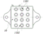
FIG. 3 is a schematic bottom view of the movable plate of the present invention;
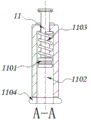
FIG. 4 is a schematic cross-sectional view taken along line A-A of FIG. 3 according to the present invention;
fig. 5 is a schematic view of a collar mounting structure of the present invention.
In the figure: 1. a first carriage; 2. a second carriage; 3. a conveyor belt; 4. a support plate; 401. a conveying roller; 5. a detonator fixing mold; 6. a collection box; 7. an arch support; 8. a hydraulic lever; 9. a guide post; 10. a movable plate; 11. withdrawing the pipe rod; 1101. a piston head; 1102. a sleeve; 1103. a return spring; 1104. sealing the rubber ring; 12. a shaft seat; 13. a collar; 1301. a limiting rod; 1302. a push rod; 1303. a roller; 14. a torsion spring; 15. and pulling a rope.
Detailed Description
The technical solutions in the embodiments of the present invention will be clearly and completely described below with reference to the drawings in the embodiments of the present invention, and it is obvious that the described embodiments are only a part of the embodiments of the present invention, and not all of the embodiments. All other embodiments, which can be derived by a person skilled in the art from the embodiments given herein without making any creative effort, shall fall within the protection scope of the present invention.
Referring to fig. 1-5, the present invention provides a technical solution: a detonator withdrawing and collecting device comprises a first conveying frame 1, a second conveying frame 2, a conveying belt 3, a supporting plate 4, a conveying roller 401, a detonator fixing mold 5, a collecting box 6, an arch support 7, a hydraulic rod 8, a guide column 9, a movable plate 10, a detonator withdrawing rod 11, a piston head 1101, a sleeve 1102, a return spring 1103, a sealing rubber ring 1104, a shaft seat 12, a sleeve ring 13, a limiting rod 1301, a push rod 1302, a roller 1303, a torsion spring 14 and a pull rope 15;
the device comprises a first conveying frame 1, a second conveying frame 2 which is a conveying mechanism and is horizontally and fixedly arranged above the first conveying frame 1, conveying belts 3 are arranged on the surfaces of the first conveying frame 1 and the second conveying frame 2, bearing plates 4 are fixed on the upper surfaces of the frame bodies of the first conveying frame 1 and the second conveying frame 2 through bolts, a detonator fixed mold 5 and a collecting box 6 are respectively arranged above the bearing plates 4 which are positioned at the upper and lower positions, and shaft seats 12 are fixedly arranged on the upper surfaces of the frame bodies of the first conveying frame 1 and the second conveying frame 2;
the arch support 7 is used as a supporting structure and is fixedly arranged above the second conveying frame 2 in an arch shape, a hydraulic rod 8 is fixedly arranged above the arch support 7 through bolts, a movable plate 10 is fixedly arranged at the lower end of the hydraulic rod 8, and 2 groups of guide columns 9 penetrating through the movable plate 10 are fixedly arranged on the lower surface of the arch support 7 through bolts;
the pipe withdrawing rod 11 is uniformly fixed on the lower surface of the movable plate 10 through a bolt, and the sleeve 1102 is sleeved on the outer side of the pipe withdrawing rod 11.
The 2 groups of conveying belts 3 used for conveying and arranged on the outer sides of the first conveying frame 1 and the second conveying frame 2 are symmetrically arranged, the distance between the 2 groups of conveying belts 3 is smaller than the width of the upper ends of the detonator fixed mold 5 and the collecting box 6, and the conveying belts 3 are flush with the upper surface of the bearing plate 4.
The bearing plates 4 are symmetrically provided with 2 groups about the first conveying frame 1, the distance between the 2 groups of bearing plates 4 is smaller than the width of the upper ends of the detonator fixing module 5 and the collecting box 6, and the upper surfaces of the bearing plates 4 are uniformly provided with conveying rollers 401 for conveying.
Through the first conveying frame 1 and the second conveying frame 2 which are arranged in parallel from top to bottom, synchronous continuous conveying can be carried out on the detonator fixed mold 5 and the collecting box 6, the vertical correspondence of the positions of the detonator fixed mold 5 and the collecting box 6 is ensured, and the first conveying frame 1 and the second conveying frame 2 can convey the detonator fixed mold 5 and the collecting box 6 to the upper part of the bearing plate 4 through the conveying belts 3 on the outer sides of the first conveying frame 1 and the second conveying frame, so that the detonator fixed mold 5 and the collecting box 6 are in a static state, and further the device can conveniently carry out the next-step pipe withdrawing operation.
The movable plate 10 and the guide post 9 for guiding form a lifting structure, a return spring 1103 for providing a return elastic force is connected between a tube withdrawing rod 11 arranged on the lower surface of the movable plate 10 and the sleeve 1102, and the position of the sleeve 1102 corresponds to the position of a mold hole structure formed on the surface of the detonator fixed mold 5.
The lower end of the pipe withdrawing rod 11 is provided with a piston head 1101 for compressed air, the piston head 1101 is in a sleeved structure with a sleeve 1102, and the lower end of the sleeve 1102 is provided with a sealing rubber ring 1104 for improving sealing performance.
Drive fly leaf 10 through control hydraulic stem 8 and move down along guide post 9, can make sleeve 1102 laminate in the upper surface of detonator fixed mould 5 gradually, when sleeve 1102 receives the conflict, move down fly leaf 10 continuously, the pipe pole 11 that moves back of fly leaf 10 lower surface can carry out elastic telescopic motion with sleeve 1102 this moment, and then make piston head 1101 compress the inboard gas of sleeve 1102, make the inboard atmospheric pressure of sleeve 1102 rise, thereby make the automatic downward discharge of detonator under the air pressure effect of detonator fixed mould 5 inboard, and fall into and collect in collecting box 6, it carries out direct contact with the detonator to have effectively avoided moving back pipe pole 11, prevent that the detonator from taking place to collide with and produce the incident.
The outer side of the shaft seat 12 is sleeved with a sleeve ring 13, a torsion spring 14 for providing reset elasticity is connected between the sleeve ring 13 and the shaft seat 12, a pull rope 15 used for traction is connected between the sleeve ring 13 and the sleeve 1102, the outer side of the sleeve ring 13 is provided with a limit rod 1301 and a push rod 1302, end shafts of the limit rod 1301 and the push rod 1302 are connected with rollers 1303, and the length of the limit rod 1301 is greater than that of the push rod 1302.
When detonator fixed mould 5, collection box 6 carry to the layer board 4 top, lantern ring 13 can be rotatory under torsion spring 14's elasticity effect, and drive gag lever post 1301 to detonator fixed mould 5, collection box 6 carries on spacing stopping, when the device is accomplished to move back the pipe, sleeve 1102 shifts up the in-process and can drive lantern ring 13 reverse rotation through stay cord 15, and then make the rotatory laminating in detonator fixed mould 5 of push rod 1302 in the lantern ring 13 outside, the outside of collection box 6, and then can push detonator fixed mould 5, collection box 6 to next section conveying mechanism, be convenient for the device carry out continuous moving back, collect, the machining efficiency of device has effectively been improved.
A method for a detonator withdrawal and collection device comprises the following steps: when the detonator withdrawing and collecting device is used, firstly, as shown in fig. 1-5, the detonator fixed mold 5 and the collecting box 6 are synchronously conveyed to the upper part of the supporting plate 4 by using the first conveying frame 1 and the second conveying frame 2, the limiting rod 1301 can clamp and limit the detonator fixed mold 5 and the collecting box 6, then the compression sleeve 1102 is attached to the surface of the detonator fixed mold 5 by moving the movable plate 10 downwards, the movable plate 10 is continuously moved downwards, the piston head 1101 can compress air in the sleeve 1102, so that detonators are automatically discharged into the collecting box 6 under the action of air pressure for collection, after the detonator withdrawing is completed, the movable plate 10 drives the sleeve 1102 to move upwards, so that the sleeve 1102 pulls the lantern ring 13 to rotate through the pull rope 15, and the push rod 1302 can synchronously push the processed detonator fixed mold 5 and the collecting box 6 to a next section of conveying mechanism, thereby completing a series of.
Those not described in detail in this specification are within the skill of the art.
Although the present invention has been described in detail with reference to the foregoing embodiments, it will be apparent to those skilled in the art that various changes in the embodiments and/or modifications of the invention can be made, and equivalents and modifications of some features of the invention can be made without departing from the spirit and scope of the invention.
Claims (7)
1. A detonator withdrawal collecting device is characterized by comprising:
the device comprises a first conveying frame, a second conveying frame, a conveying mechanism, a detonator fixing frame and a collecting box, wherein the first conveying frame is horizontally placed on the ground of a processing workshop, the second conveying frame which is the same as the conveying mechanism is horizontally and fixedly arranged above the first conveying frame, conveying belts are respectively arranged on the surfaces of the first conveying frame and the second conveying frame, bearing plates are respectively fixed on the upper surfaces of the frame bodies of the first conveying frame and the second conveying frame through bolts, meanwhile, the detonator fixing frame and the collecting box are respectively arranged above the bearing plates which are positioned at the upper position and the lower position, and shaft seats are respectively fixedly arranged on the upper surfaces of the frame bodies of the first conveying frame;
the arch center is fixedly arranged above the second conveying frame in an arch shape as a supporting structure, a hydraulic rod is fixedly arranged above the arch center through bolts, a movable plate is fixedly arranged at the lower end of the hydraulic rod, and 2 groups of guide columns penetrating through the movable plate are fixedly arranged on the lower surface of the arch center through bolts;
the pipe withdrawing rod is uniformly fixed on the lower surface of the movable plate through bolts, and the sleeve is sleeved on the outer side of the pipe withdrawing rod.
2. The detonator withdrawal collecting device according to claim 1, wherein: the 2 groups of conveying belts for conveying are symmetrically arranged on the outer sides of the first conveying frame and the second conveying frame, the distance between the 2 groups of conveying belts is smaller than the width of the upper ends of the detonator fixed mold and the collecting box, and the conveying belts are flush with the upper surface of the bearing plate.
3. The detonator withdrawal collecting device according to claim 2, wherein: the supporting plates are symmetrically provided with 2 groups relative to the first conveying frame, the distance between the 2 groups of supporting plates is smaller than the width of the upper ends of the detonator fixed mold and the collecting box, and the upper surfaces of the supporting plates are uniformly provided with conveying rollers playing a conveying role.
4. The detonator withdrawal collecting device according to claim 1, wherein: the movable plate and the guide post which plays a role in guiding form a lifting structure, a return spring which provides return elasticity is connected between a tube withdrawing rod arranged on the lower surface of the movable plate and the sleeve, and the position of the sleeve corresponds to the position of a die hole structure formed on the surface of the detonator fixed die.
5. A detonator withdrawal collecting device according to claim 4, wherein: the lower end of the pipe withdrawing rod is provided with a piston head for compressing air, the piston head is in a sleeve structure, and the lower end of the sleeve is provided with a sealing rubber ring for improving the sealing performance.
6. The detonator withdrawal collecting device according to claim 1, wherein: the lantern ring has been cup jointed in the outside of axle bed, just be connected with the torsion spring who provides the elasticity that resets between lantern ring and the axle bed, and be connected with between lantern ring and the sleeve and be used as towed stay cord, simultaneously the outside of lantern ring is provided with gag lever post and push rod respectively, moreover gag lever post, push rod both's end hub connection have the gyro wheel, just the length of gag lever post is greater than the length of push rod.
7. A detonator withdrawal collecting device based on claim 1, which is characterized in that: firstly, a first conveying frame and a second conveying frame are used for conveying a detonator fixed mold and a collecting box to the upper side of a supporting plate synchronously, a limiting rod can clamp and limit the detonator fixed mold and the collecting box, then the movable plate moves downwards to enable a compression sleeve to be attached to the surface of the detonator fixed mold, the movable plate continues to move downwards to enable a piston head to compress air in the sleeve, so that a detonator is automatically discharged into the collecting box under the action of air pressure to be collected, after pipe withdrawal is completed, the movable plate drives the sleeve to move upwards to enable the sleeve to be rotated through a pull rope to pull a sleeve ring, and a push rod pushes the processed detonator fixed mold and the collecting box to a conveying mechanism at a lower section synchronously.
Priority Applications (1)
| Application Number | Priority Date | Filing Date | Title |
|---|---|---|---|
| CN202110342738.6A CN113045369B (en) | 2021-03-30 | 2021-03-30 | Detonator withdrawal collecting device and method |
Applications Claiming Priority (1)
| Application Number | Priority Date | Filing Date | Title |
|---|---|---|---|
| CN202110342738.6A CN113045369B (en) | 2021-03-30 | 2021-03-30 | Detonator withdrawal collecting device and method |
Publications (2)
| Publication Number | Publication Date |
|---|---|
| CN113045369A true CN113045369A (en) | 2021-06-29 |
| CN113045369B CN113045369B (en) | 2022-06-17 |
Family
ID=76516438
Family Applications (1)
| Application Number | Title | Priority Date | Filing Date |
|---|---|---|---|
| CN202110342738.6A Active CN113045369B (en) | 2021-03-30 | 2021-03-30 | Detonator withdrawal collecting device and method |
Country Status (1)
| Country | Link |
|---|---|
| CN (1) | CN113045369B (en) |
Cited By (1)
| Publication number | Priority date | Publication date | Assignee | Title |
|---|---|---|---|---|
| CN119986338A (en) * | 2025-04-15 | 2025-05-13 | 黑龙江青化民爆器材有限公司 | A defect detection method and system for integrated circuit manufacturing |
Citations (4)
| Publication number | Priority date | Publication date | Assignee | Title |
|---|---|---|---|---|
| CN2044344U (en) * | 1988-09-20 | 1989-09-13 | 刘永江 | Automatic producing machine for detonator |
| RU29996U1 (en) * | 2002-12-10 | 2003-06-10 | Открытое акционерное общество по производству взрывчатых материалов и пиротехники "Нитро-Взрыв" | Detonator checker |
| CN206089499U (en) * | 2016-06-28 | 2017-04-12 | 西安庆华民用爆破器材股份有限公司 | Automatic gathering machine that withdraws from of detonator |
| CN206486456U (en) * | 2016-11-25 | 2017-09-12 | 西安庆华民用爆破器材股份有限公司 | A kind of detonator receives box machine automatically |
-
2021
- 2021-03-30 CN CN202110342738.6A patent/CN113045369B/en active Active
Patent Citations (4)
| Publication number | Priority date | Publication date | Assignee | Title |
|---|---|---|---|---|
| CN2044344U (en) * | 1988-09-20 | 1989-09-13 | 刘永江 | Automatic producing machine for detonator |
| RU29996U1 (en) * | 2002-12-10 | 2003-06-10 | Открытое акционерное общество по производству взрывчатых материалов и пиротехники "Нитро-Взрыв" | Detonator checker |
| CN206089499U (en) * | 2016-06-28 | 2017-04-12 | 西安庆华民用爆破器材股份有限公司 | Automatic gathering machine that withdraws from of detonator |
| CN206486456U (en) * | 2016-11-25 | 2017-09-12 | 西安庆华民用爆破器材股份有限公司 | A kind of detonator receives box machine automatically |
Cited By (1)
| Publication number | Priority date | Publication date | Assignee | Title |
|---|---|---|---|---|
| CN119986338A (en) * | 2025-04-15 | 2025-05-13 | 黑龙江青化民爆器材有限公司 | A defect detection method and system for integrated circuit manufacturing |
Also Published As
| Publication number | Publication date |
|---|---|
| CN113045369B (en) | 2022-06-17 |
Similar Documents
| Publication | Publication Date | Title |
|---|---|---|
| CN203246871U (en) | Lifting apparatus for placing base for large refrigerator | |
| CN105033090B (en) | Integrated full-automatic can making machine | |
| CN214391669U (en) | Multi-tube synchronous cold-drawing machine | |
| CN110370793A (en) | A kind of automatic thermoprinting machine and its hot stamping method | |
| CN113045369B (en) | Detonator withdrawal collecting device and method | |
| CN213704522U (en) | Quick discharge mechanism for plastic uptake molding | |
| CN205223737U (en) | Pulp moulding shaping machine | |
| CN221028108U (en) | Curved toughened glass auxiliary forming device | |
| CN219884870U (en) | Mold core conveyor for hollow building blocks | |
| CN221456677U (en) | A demoulding device | |
| CN118045890A (en) | An intelligent automatic manufacturing and assembly device for cable trays | |
| CN220259397U (en) | Copper busbar mechanism of bending | |
| CN208714571U (en) | Canopy molding structure | |
| CN219944406U (en) | Shaping stamping die based on machining can drawing of patterns fast | |
| CN219789039U (en) | Vacuum mechanical integrated bubble opening machine | |
| CN216801403U (en) | Riveting machine | |
| CN117946701A (en) | Coke pushing rod supporting device for coke pushing vehicle | |
| CN206543829U (en) | Mobile die-filling platform | |
| CN214647383U (en) | Automatic assembling machine for solid tire of electric bicycle | |
| CN212682570U (en) | Plate shearing machine for processing guardrail plate | |
| CN210456835U (en) | A gravity-balanced storage device | |
| CN115339888A (en) | Adjustable carrying device for steel processing | |
| CN209812097U (en) | Automatic change emery wheel manufacture equipment | |
| CN106272701A (en) | A kind of punch press automatic plate collecting machine of band alignment function | |
| CN220532810U (en) | Aluminium alloy straightening machine |
Legal Events
| Date | Code | Title | Description |
|---|---|---|---|
| PB01 | Publication | ||
| PB01 | Publication | ||
| SE01 | Entry into force of request for substantive examination | ||
| SE01 | Entry into force of request for substantive examination | ||
| GR01 | Patent grant | ||
| GR01 | Patent grant |