CN113026273A - Prevent textile fabric stoving auxiliary structure of fold - Google Patents
Prevent textile fabric stoving auxiliary structure of fold Download PDFInfo
- Publication number
- CN113026273A CN113026273A CN202110234409.XA CN202110234409A CN113026273A CN 113026273 A CN113026273 A CN 113026273A CN 202110234409 A CN202110234409 A CN 202110234409A CN 113026273 A CN113026273 A CN 113026273A
- Authority
- CN
- China
- Prior art keywords
- movably connected
- outer side
- connecting block
- push rod
- spring
- Prior art date
- Legal status (The legal status is an assumption and is not a legal conclusion. Google has not performed a legal analysis and makes no representation as to the accuracy of the status listed.)
- Withdrawn
Links
- 239000004744 fabric Substances 0.000 title claims abstract description 57
- 239000004753 textile Substances 0.000 title claims abstract description 28
- 238000001035 drying Methods 0.000 claims abstract description 22
- 238000010438 heat treatment Methods 0.000 claims abstract description 21
- 238000009434 installation Methods 0.000 claims description 21
- 230000006978 adaptation Effects 0.000 claims description 2
- 238000005096 rolling process Methods 0.000 claims description 2
- 238000010409 ironing Methods 0.000 abstract description 5
- 238000010981 drying operation Methods 0.000 abstract description 4
- XEEYBQQBJWHFJM-UHFFFAOYSA-N Iron Chemical compound [Fe] XEEYBQQBJWHFJM-UHFFFAOYSA-N 0.000 abstract 2
- 229910052742 iron Inorganic materials 0.000 abstract 1
- 230000037303 wrinkles Effects 0.000 abstract 1
- 238000009941 weaving Methods 0.000 description 7
- 239000000463 material Substances 0.000 description 5
- 238000005516 engineering process Methods 0.000 description 4
- 230000001153 anti-wrinkle effect Effects 0.000 description 3
- 230000009471 action Effects 0.000 description 2
- 230000005540 biological transmission Effects 0.000 description 2
- 230000000694 effects Effects 0.000 description 2
- 238000000034 method Methods 0.000 description 2
- 230000008569 process Effects 0.000 description 2
- 238000009987 spinning Methods 0.000 description 2
- 238000004804 winding Methods 0.000 description 2
- 230000004075 alteration Effects 0.000 description 1
- 230000001174 ascending effect Effects 0.000 description 1
- 230000009286 beneficial effect Effects 0.000 description 1
- 230000000739 chaotic effect Effects 0.000 description 1
- 150000001875 compounds Chemical class 0.000 description 1
- 238000012986 modification Methods 0.000 description 1
- 230000004048 modification Effects 0.000 description 1
- 239000004745 nonwoven fabric Substances 0.000 description 1
- 230000001737 promoting effect Effects 0.000 description 1
- 238000006467 substitution reaction Methods 0.000 description 1
- 238000009423 ventilation Methods 0.000 description 1
Images




Classifications
-
- D—TEXTILES; PAPER
- D06—TREATMENT OF TEXTILES OR THE LIKE; LAUNDERING; FLEXIBLE MATERIALS NOT OTHERWISE PROVIDED FOR
- D06B—TREATING TEXTILE MATERIALS USING LIQUIDS, GASES OR VAPOURS
- D06B15/00—Removing liquids, gases or vapours from textile materials in association with treatment of the materials by liquids, gases or vapours
- D06B15/09—Removing liquids, gases or vapours from textile materials in association with treatment of the materials by liquids, gases or vapours by jets of gases
-
- D—TEXTILES; PAPER
- D06—TREATMENT OF TEXTILES OR THE LIKE; LAUNDERING; FLEXIBLE MATERIALS NOT OTHERWISE PROVIDED FOR
- D06B—TREATING TEXTILE MATERIALS USING LIQUIDS, GASES OR VAPOURS
- D06B23/00—Component parts, details, or accessories of apparatus or machines, specially adapted for the treating of textile materials, not restricted to a particular kind of apparatus, provided for in groups D06B1/00 - D06B21/00
- D06B23/02—Rollers
-
- D—TEXTILES; PAPER
- D06—TREATMENT OF TEXTILES OR THE LIKE; LAUNDERING; FLEXIBLE MATERIALS NOT OTHERWISE PROVIDED FOR
- D06C—FINISHING, DRESSING, TENTERING OR STRETCHING TEXTILE FABRICS
- D06C15/00—Calendering, pressing, ironing, glossing or glazing textile fabrics
- D06C15/10—Calendering, pressing, ironing, glossing or glazing textile fabrics between flat plates of a press
Landscapes
- Engineering & Computer Science (AREA)
- Textile Engineering (AREA)
- Treatment Of Fiber Materials (AREA)
Abstract
The invention relates to the technical field of textile, and discloses a wrinkle-preventing textile fabric drying auxiliary structure which comprises a cam, wherein a connecting block is movably connected above the cam, a mounting spring is movably connected to the outer side of the connecting block, hot air is conveyed into a heating plate through a U-shaped pipe and is blown out from a ventilating pipeline to perform drying operation, the guide spring is matched with a guide wheel to prevent cloth from being wound between the heating plates in a disordered manner, an ironing plate in the heating plate is driven to be attached to the cloth through the matching of a driving gear, a toothed plate and a push plate to iron the cloth to eliminate wrinkles of the cloth, when three groups of push rods are respectively pushed to move outwards through the cam and the connecting block, the space among the three groups of guide rollers is increased, the tension between the dried cloth is improved, the wrinkle-preventing textile fabric drying auxiliary structure is suitable for textile fabrics with different thicknesses, and meanwhile, the matching of an inclined rod, the push rod is prevented from being broken, and the safety practicability of the device is further improved.
Description
Technical Field
The invention relates to the technical field of textiles, in particular to an anti-wrinkle textile fabric drying auxiliary structure.
Background
The weaving principle is a general name taken from spinning and weaving, but with the continuous development and perfection of a weaving knowledge system and a subject system, particularly after the technologies of non-woven textile materials, three-dimensional compound weaving and the like are produced, the weaving principle not only comprises the traditional hand-made spinning and weaving, but also comprises the non-woven fabric technology, the modern three-dimensional weaving technology, the modern electrostatic nano-web technology and the like.
Textile material need use drying device to dry textile material after processing is washd, but current drying device drying efficiency is low when drying textile material, because the desiccation when the cloth is dried, can make the fold appear in the cloth, influences the appearance quality, and in drying equipment, when the cloth passes through conveyer, moist cloth is easily knotted, twined.
In order to solve the above problems, the inventor provides an auxiliary drying structure for wrinkle-proof textile fabric, which has the advantages of ironing the fabric while drying, and the fabric is not easy to knot and wind.
Disclosure of Invention
In order to achieve the purpose, the invention provides the following technical scheme: an anti-wrinkle textile fabric drying auxiliary structure comprises a cam, wherein a connecting block is movably connected above the cam, an installation spring is movably connected to the outer side of the connecting block, a push rod is movably connected to the outer side of the installation spring, a return spring is movably connected to the outer side of the push rod, an installation wheel carrier is movably connected to the outer side of the return spring, a slider is movably connected to the outer side of the installation wheel carrier, an inclined rod is movably connected to the outer side of the slider, a supporting table is movably connected to the outer side of the inclined rod, a guide roller is movably connected to the outer side of the supporting table, a U-shaped pipe is movably connected to the outer side of the guide roller, a heating plate is movably connected to the lower side of the U-shaped pipe, an air pipe is movably connected to the inner side of the heating plate, the outer side swing joint of leading wheel has the guide spring, the outer side swing joint of guide spring has the driving gear, the outside meshing of driving gear is connected with the pinion rack, the outside swing joint of pinion rack has the push pedal.
Preferably, the below of connecting block is provided with two sets of pulleys, and the lower extreme of connecting block passes through pulley and cam swing joint, the push rod swing joint of the upper end and the upper end of connecting block, and the left and right sides of connecting block is provided with the butt inclined plane simultaneously.
Preferably, the push rod is provided with three groups, and controls two sets of push rods and pass through installation spring and connecting block swing joint, and controls the inboard of two sets of push rods and be provided with the butt inclined plane with connecting block looks adaptation, and the outside of three groups of push rods all is provided with the spout, all is provided with the answer spring in the spout simultaneously.
Preferably, four groups of arc-shaped sliding grooves are formed in the outer side of the mounting wheel carrier, arc-shaped springs are arranged in the sliding grooves, and the sliding blocks are arranged in the sliding grooves and movably connected with the arc-shaped springs.
Preferably, two sets of hinged bayonets are arranged at one end of the inner side of the supporting table, one end of the outer side of the diagonal rod is movably connected in the hinged bayonets, meanwhile, the push rod penetrates through the supporting table and is movably connected with the rotating shaft of the guide roller, and a rolling bearing is arranged between the push rod and the rotating shaft of the guide roller.
Preferably, the guide wheel and the guide spring are in a group, one end of the outer side of the guide wheel is hinged in the internal hinged bayonet of the heating plate through the guide shaft, one end of the outer side of the guide spring is hinged on the inner side of the heating plate, and one end of the outer side of the guide spring is hinged in the middle of the guide shaft.
Preferably, the driving gear is driven by a forward and reverse rotation motor, the upper side and the lower side of the driving gear are respectively engaged and connected with a toothed plate, one end of the outer side of the toothed plate is respectively movably connected with a push plate, and the push plate is movably connected with the heating plate on the outer side.
Advantageous effects
Compared with the prior art, the invention provides a wrinkle-preventing textile fabric drying auxiliary structure, which has the following beneficial effects:
1. this prevent textile fabric stoving auxiliary structure of fold carries the air pipe of hot-air to the hot plate through the U-shaped pipe, blows off from air pipe, dries the operation, and in the cloth data send process, under guide spring's ejecting effect, the leading wheel laminates the cloth all the time, can keep gentle and agreeable steady state when making the cloth get into the hot plate, prevents the chaotic winding problem of cloth between the hot plate.
2. This prevent textile fabric stoving auxiliary structure of fold, when through driving gear anticlockwise rotation, drive both sides meshed's pinion rack and push pedal and move to the inboard, the push pedal drives the whole inboard removal of hot plate of both sides simultaneously, and the inside screed of hot plate begins to laminate the cloth, flattens the cloth, eliminates on the cloth because the fold that appears by drying, improves the quality of the cloth of producing
3. This prevent textile fabric stoving auxiliary structure of fold, when promoting three group's push rods respectively through cam and connecting block and moving to the outside simultaneously, interval increase between the outer three group guide rolls of installation wheel carrier, can improve the tension between the stoving cloth, also can use the textile fabric of different thickness, the device's practicality has been strengthened, two sets of down tube of brace table inboard can move to the inboard simultaneously, the down tube drives the slider and slides in the spout of installation wheel carrier, compress the arc spring in the spout, can provide certain buffer capacity for guide roll and push rod, prevent that the guide roll from leading for a long time and drive the cloth operation, make the condition of push rod rupture, the practicality of the device's security has further been improved.
Drawings
FIG. 1 is a schematic view of the overall structure of the present invention;
FIG. 2 is a schematic view of a portion of the mounting wheel frame of FIG. 1 in accordance with the present invention;
FIG. 3 is a schematic view of a portion of the support table of FIG. 1 according to the present invention;
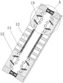
FIG. 4 is a schematic view of a portion of the heating plate of FIG. 1 according to the present invention;
FIG. 5 is an enlarged view of the structure at A of FIG. 4 according to the present invention;
FIG. 6 is an enlarged view of the structure at B of FIG. 5 according to the present invention.
In the figure: 1. a cam; 2. connecting blocks; 3. installing a spring; 4. a push rod; 5. a return spring; 6. mounting a wheel carrier; 7. a slider; 8. a diagonal bar; 9. a support table; 10. a guide roller; 11. a U-shaped tube; 12. heating plates; 13. a ventilation duct; 14. a screed plate; 15. a guide wheel; 16. a guide spring; 17. a driving gear; 18. a toothed plate; 19. a push plate.
Detailed Description
The technical solutions in the embodiments of the present invention will be clearly and completely described below with reference to the drawings in the embodiments of the present invention, and it is obvious that the described embodiments are only a part of the embodiments of the present invention, and not all of the embodiments. All other embodiments, which can be derived by a person skilled in the art from the embodiments given herein without making any creative effort, shall fall within the protection scope of the present invention.
Referring to fig. 1-6, an anti-wrinkle textile fabric drying auxiliary structure comprises a cam 1, a connecting block 2 is movably connected above the cam 1, an installation spring 3 is movably connected outside the connecting block 2, a push rod 4 is movably connected outside the installation spring 3, two groups of pulleys are arranged below the connecting block 2, the lower end of the connecting block 2 is movably connected with the cam 1 through the pulleys, the upper end of the connecting block 2 is movably connected with the push rod 4 at the upper end, the left side and the right side of the connecting block 2 are provided with abutting inclined planes, the outer side of the push rod 4 is movably connected with a return spring 5, the push rod 4 is provided with three groups, the left push rod 4 and the right push rod 4 are movably connected with the connecting block 2 through the installation spring 3, the inner sides of the left push rod 4 and the right push rod 4 are provided with abutting inclined planes matched with the connecting block, the outer side of the return spring 5 is movably connected with a mounting wheel carrier 6.
The outside swing joint of installation wheel carrier 6 has slider 7, the outside of installation wheel carrier 6 is provided with four curved spouts of group, be provided with the arc spring in the spout, and slider 7 sets up in the spout, with arc spring swing joint, the outside of slider 7 articulates there is down tube 8, the outside swing joint of down tube 8 has brace table 9, the outside swing joint of brace table 9 has guide roll 10, the inboard one end of brace table 9 is provided with two sets of articulated bayonets, the outside one end swing joint of down tube 8 is in the articulated bayonet, push rod 4 passes the axis of rotation swing joint of brace table 9 with guide roll 10 simultaneously, and be provided with antifriction bearing between the axis of rotation of push rod 4 and guide roll 10.
The outer side of the guide roller 10 is movably connected with a U-shaped pipe 11, the lower part of the U-shaped pipe 11 is movably connected with a heating plate 12, the inner part of the heating plate 12 is movably connected with a ventilating duct 13, hot air for drying is conveyed into the ventilating duct 13 of the heating plate 12 through the U-shaped pipe 11 during drying operation, the inner side of the ventilating duct 13 is movably connected with an ironing plate 14, the upper part of the ironing plate 14 is movably connected with a guide wheel 15, the outer side of the guide wheel 15 is movably connected with a guide spring 16, the four guide wheels 15 and the guide spring 16 form a group, one end of the outer side of the guide wheel 15 is hinged in an inner hinged bayonet of the heating plate 12 through a guide shaft, one end of the outer side of the guide spring 16 is hinged at the inner side of the heating plate 12, one end of the outer side is hinged, the outside swing joint of pinion rack 18 has push pedal 19, and driving gear 17 is by the motor drive of just reversing, and the upper and lower both sides of driving gear 17 all mesh simultaneously and are connected with a pinion rack 18, and each swing joint has a push pedal 19 in the outside one end of pinion rack 18, push pedal 19 and the hot plate 12 swing joint in the outside.
The working process and principle are as follows: according to the drawing, the textile fabric to be dried sequentially passes through three guide rollers 10 and two groups of heating plates 12 according to the drawing I, the wet fabric sequentially passes through the left and right groups of heating plates 12 along with the transmission action of the three groups of guide rollers 10, during the drying operation, hot air for drying is conveyed into a ventilating pipeline 13 of the heating plates 12 through a U-shaped pipe 11 and is blown out from the ventilating pipeline 13 to perform the drying operation, during the fabric transmission process, under the ejection action of a guide spring 16, a guide wheel 15 is always attached to the fabric, so that the fabric can be kept in a stable state when entering the heating plates 12, the problem of disordered winding of the fabric between the heating plates 12 is solved, meanwhile, the guide wheel 15 can effectively prevent the attached sundries on the fabric from entering between the two groups of flat plates, the ironing plate 14 is prevented from being damaged by the sundries, a positive and negative rotation, drive both sides engaged toothed plate 18 and push pedal 19 and move to the inboard, and push pedal 19 drives the whole inboard removal of hot plate 12 of both sides simultaneously, and the inside screed 14 of hot plate 12 begins to laminate the cloth, flattens the cloth, eliminates the fold that appears because being dried on the cloth, improves the quality of the cloth of producing.
When different varieties of cloth materials with different thicknesses are dried, the cam 1 can be rotated, when the cam 1 rotates, the convex part of the cam 1 contacts with the upper pulley, the connecting block 2 is pushed to move upwards, when the connecting block 2 moves upwards, firstly, the upper group of push rods 4 is pushed to move upwards, the return springs 5 on the outer sides of the push rods 4 are compressed, meanwhile, the left and right groups of push rods 4 are pushed to respectively move leftwards and rightwards due to the abutting inclined planes on the side surfaces of the connecting block 2, the return springs 5 on the outer sides are simultaneously compressed, meanwhile, the installation springs 3 hinged between the left and right groups of push rods 4 and the connecting block 2 are changed from a horizontal state to an inclined state, the installation springs 3 are lengthened, when the three groups of push rods 4 simultaneously move outwards, the distance among the three groups of guide rollers 10 outside the installation wheel frame 6 is increased, the tension between the dried, the practicability of the device is enhanced.
In the stoving operation, guide roll 10 drives the cloth operation, especially the guide roll 10 of both sides, receive the ascending thrust of cloth for a long time, make the push rod 4 of both sides damage easily, and two sets of down tube 8 of brace table 9 inboard can move to the inboard, down tube 8 drives slider 7 and slides in the spout of installation wheel carrier 6, compress the arc spring in the spout simultaneously, can provide certain buffer capacity for guide roll 10 and push rod 4, prevent that the long-time conduction band of guide roll 10 from moving the cloth operation, make the condition of push rod 4 rupture, the practicality of the security of the device has further been improved.
Although embodiments of the present invention have been shown and described, it will be appreciated by those skilled in the art that changes, modifications, substitutions and alterations can be made in these embodiments without departing from the principles and spirit of the invention, the scope of which is defined in the appended claims and their equivalents.
Claims (7)
1. The utility model provides a prevent textile fabric stoving auxiliary structure of fold, includes cam (1), its characterized in that: the upper swing joint of the cam (1) is provided with a connecting block (2), the outer side of the connecting block (2) is movably connected with an installation spring (3), the outer side of the installation spring (3) is movably connected with a push rod (4), the outer side of the push rod (4) is movably connected with a return spring (5), the outer side of the return spring (5) is movably connected with an installation wheel carrier (6), the outer side of the installation wheel carrier (6) is movably connected with a slide block (7), the outer side of the slide block (7) is movably connected with an inclined rod (8), the outer side of the inclined rod (8) is movably connected with a supporting table (9), the outer side of the supporting table (9) is movably connected with a guide roller (10), the outer side of the guide roller (10) is movably connected with a U-shaped pipe (11), the lower side of the U-shaped pipe (11) is movably connected with a, the inboard swing joint of air pipe (13) has screed (14), the top swing joint of screed (14) has leading wheel (15), the outside swing joint of leading wheel (15) has guide spring (16), the outside swing joint of guide spring (16) has driving gear (17), the outside meshing of driving gear (17) is connected with pinion rack (18), the outside swing joint of pinion rack (18) has push pedal (19).
2. The anti-wrinkling textile fabric drying auxiliary structure according to claim 1, wherein: the below of connecting block (2) is provided with two sets of pulleys, and the lower extreme of connecting block (2) passes through pulley and cam (1) swing joint, the upper end of connecting block (2) and push rod (4) swing joint of upper end, and the left and right sides of connecting block (2) is provided with the butt inclined plane simultaneously.
3. The anti-wrinkling textile fabric drying auxiliary structure according to claim 1, wherein: push rod (4) are provided with three groups, and control two sets of push rod (4) through installation spring (3) and connecting block (2) swing joint, and control the inboard of two sets of push rod (4) and be provided with the butt inclined plane of connecting block (2) looks adaptation, the outside of three push rod groups (4) all is provided with the spout, all is provided with in the spout simultaneously and replies spring (5).
4. The anti-wrinkling textile fabric drying auxiliary structure according to claim 1, wherein: the outer side of the mounting wheel carrier (6) is provided with four groups of arc-shaped sliding grooves, arc-shaped springs are arranged in the sliding grooves, and the sliding blocks (7) are arranged in the sliding grooves and movably connected with the arc-shaped springs.
5. The anti-wrinkling textile fabric drying auxiliary structure according to claim 1, wherein: two sets of hinged bayonets are arranged at one end of the inner side of the supporting table (9), one end of the outer side of the inclined rod (8) is movably connected into the hinged bayonets, meanwhile, the push rod (4) penetrates through the supporting table (9) and is movably connected with a rotating shaft of the guide roller (10), and a rolling bearing is arranged between the push rod (4) and the rotating shaft of the guide roller (10).
6. The anti-wrinkling textile fabric drying auxiliary structure according to claim 1, wherein: guide wheel (15) and guide spring (16) four are a set of, and the outside one end of guide wheel (15) is articulated in the inside articulated bayonet socket of hot plate (12) through the guiding axle, and the outside one end of guide spring (16) articulates at hot plate (12) inboard simultaneously, and outside one end articulates at the middle part of guiding axle.
7. The anti-wrinkling textile fabric drying auxiliary structure according to claim 1, wherein: the driving gear (17) is driven by a forward and reverse rotating motor, the upper side and the lower side of the driving gear (17) are respectively connected with a toothed plate (18) in a meshed mode, one end of the outer side of each toothed plate (18) is movably connected with a push plate (19), and the push plates (19) are movably connected with the heating plate (12) on the outer side.
Priority Applications (1)
| Application Number | Priority Date | Filing Date | Title |
|---|---|---|---|
| CN202110234409.XA CN113026273A (en) | 2021-03-03 | 2021-03-03 | Prevent textile fabric stoving auxiliary structure of fold |
Applications Claiming Priority (1)
| Application Number | Priority Date | Filing Date | Title |
|---|---|---|---|
| CN202110234409.XA CN113026273A (en) | 2021-03-03 | 2021-03-03 | Prevent textile fabric stoving auxiliary structure of fold |
Publications (1)
| Publication Number | Publication Date |
|---|---|
| CN113026273A true CN113026273A (en) | 2021-06-25 |
Family
ID=76466436
Family Applications (1)
| Application Number | Title | Priority Date | Filing Date |
|---|---|---|---|
| CN202110234409.XA Withdrawn CN113026273A (en) | 2021-03-03 | 2021-03-03 | Prevent textile fabric stoving auxiliary structure of fold |
Country Status (1)
| Country | Link |
|---|---|
| CN (1) | CN113026273A (en) |
Cited By (1)
| Publication number | Priority date | Publication date | Assignee | Title |
|---|---|---|---|---|
| CN113584775A (en) * | 2021-08-02 | 2021-11-02 | 杭州福蕙科技有限公司 | Three proofings arrangement knitting spinning cloth drying device |
-
2021
- 2021-03-03 CN CN202110234409.XA patent/CN113026273A/en not_active Withdrawn
Cited By (1)
| Publication number | Priority date | Publication date | Assignee | Title |
|---|---|---|---|---|
| CN113584775A (en) * | 2021-08-02 | 2021-11-02 | 杭州福蕙科技有限公司 | Three proofings arrangement knitting spinning cloth drying device |
Similar Documents
| Publication | Publication Date | Title |
|---|---|---|
| CN208860068U (en) | A fabric rotary drying device | |
| CN109179000B (en) | Non-woven fabric winding device with static electricity removing and drying functions | |
| CN115200341A (en) | Textile processing drying device based on internet of things | |
| CN113353710A (en) | Textile fabric wrinkle removing device for fabric processing | |
| CN116853882B (en) | Textile fabric traction equipment with heating function | |
| CN114507960B (en) | Drying and shaping integrated machine for dyed non-woven fabrics | |
| CN219238703U (en) | Cloth coiling mechanism is used in weaving | |
| CN218936932U (en) | Drying equipment is used in yarn production | |
| CN110849119B (en) | Energy-efficient non-woven fabrics drying device | |
| CN108224973B (en) | A cloth drying device | |
| CN207610499U (en) | A kind of textile oven | |
| CN208762727U (en) | A kind of drying unit of forming machine | |
| CN220952554U (en) | Textile fabric removes fold device | |
| CN110592869B (en) | Novel washing machine | |
| CN218645965U (en) | Cloth air-drying device for textile industry | |
| CN117606214A (en) | Textile fabric drying device | |
| CN206989646U (en) | A kind of side-by-side drying cylinder dries cloth apparatus | |
| CN211012321U (en) | Drying equipment for knitted textile fabric | |
| CN116625085A (en) | An energy-saving high-speed dryer for knitting equipment | |
| CN213624772U (en) | Drying-machine for dyeing and finishing sampling | |
| CN217636618U (en) | Weaving drying device for textile production | |
| CN223116984U (en) | A wrinkle-proof storage box for textile manufacturing | |
| CN223792593U (en) | A fabric weaving and winding device | |
| CN220670083U (en) | Drying and dewatering device for water-jet loom | |
| CN211947545U (en) | Printing and dyeing device for spinning convenient to print and dye fast |
Legal Events
| Date | Code | Title | Description |
|---|---|---|---|
| PB01 | Publication | ||
| PB01 | Publication | ||
| SE01 | Entry into force of request for substantive examination | ||
| SE01 | Entry into force of request for substantive examination | ||
| WW01 | Invention patent application withdrawn after publication |
Application publication date: 20210625 |
|
| WW01 | Invention patent application withdrawn after publication |