CN113005911B - Bridge girder erection machine assembling method - Google Patents
Bridge girder erection machine assembling method Download PDFInfo
- Publication number
- CN113005911B CN113005911B CN202110231011.0A CN202110231011A CN113005911B CN 113005911 B CN113005911 B CN 113005911B CN 202110231011 A CN202110231011 A CN 202110231011A CN 113005911 B CN113005911 B CN 113005911B
- Authority
- CN
- China
- Prior art keywords
- assembly
- guide beam
- longitudinal guide
- support leg
- section
- Prior art date
- Legal status (The legal status is an assumption and is not a legal conclusion. Google has not performed a legal analysis and makes no representation as to the accuracy of the status listed.)
- Active
Links
Images



Classifications
-
- E—FIXED CONSTRUCTIONS
- E01—CONSTRUCTION OF ROADS, RAILWAYS, OR BRIDGES
- E01D—CONSTRUCTION OF BRIDGES, ELEVATED ROADWAYS OR VIADUCTS; ASSEMBLY OF BRIDGES
- E01D21/00—Methods or apparatus specially adapted for erecting or assembling bridges
-
- E—FIXED CONSTRUCTIONS
- E01—CONSTRUCTION OF ROADS, RAILWAYS, OR BRIDGES
- E01D—CONSTRUCTION OF BRIDGES, ELEVATED ROADWAYS OR VIADUCTS; ASSEMBLY OF BRIDGES
- E01D21/00—Methods or apparatus specially adapted for erecting or assembling bridges
- E01D21/06—Methods or apparatus specially adapted for erecting or assembling bridges by translational movement of the bridge or bridge sections
Landscapes
- Engineering & Computer Science (AREA)
- Architecture (AREA)
- Civil Engineering (AREA)
- Structural Engineering (AREA)
- Bridges Or Land Bridges (AREA)
Abstract
The invention discloses a bridge girder erection machine assembling method, which belongs to the technical field of bridge engineering, wherein first sections of two longitudinal guide beam assemblies are arranged on a front support leg assembly and a middle support leg assembly, the end part of the first section of the longitudinal guide beam assembly far away from a tunnel is provided with the next longitudinal guide beam assembly first section, all the longitudinal guide beam assembly first sections move towards the tunnel direction, the middle support leg assembly is detached and moves to the vicinity of a rear support leg assembly, at the moment, all the longitudinal guide beam assembly first sections are supported through the rear support leg assembly and the front support leg assembly, the middle support leg assembly is fixed, the rear support leg assembly is released from being fixed, all the longitudinal guide beam assembly first sections are supported through the front support leg assembly and the middle support leg assembly, and the next longitudinal guide beam assembly first section is continuously installed through the steps, so that the bridge girder erection machine is assembled and constructed on a narrow roadbed at a tunnel entrance. The bridge girder erection machine assembling method provided by the invention is not limited by the space size of the tunnel, and has the advantages of small assembling difficulty, low risk and short construction period.
Description
Technical Field
The invention relates to the technical field of bridge engineering, in particular to a bridge girder erection machine assembling method.
Background
In bridge engineering, the prefabricated T-shaped beams or box girder bridges are widely applied to highway construction due to the advantages of simple structure, mature technology, economic manufacturing cost, convenience in maintenance and the like, and when the number of the prefabricated T-shaped beams or box girders is large, the prefabricated T-shaped beams or box girder bridges are generally installed by using bridge erecting machines, and due to the special use, the bridge erecting machines are large in size. Generally, the bridge girder erection machine is assembled and formed on a wide roadbed by using a truck crane, and the length of the roadbed is greater than that of the bridge girder erection machine. However, when a highway is constructed in a mountain area, the proportion of the number of bridges and tunnels is often large, the number of roadbeds is small and short, and the condition that the distance between the bridges and the tunnels is extremely short is often met due to the restriction of the terrain conditions in the mountain area.
In the construction process, because of the construction needs, can often carry out the construction of assembling of bridging machine on the narrow road bed of tunnel entrance to a cave, but the road bed paragraph is extremely short, can't assemble the shaping with bridging machine according to conventional construction process, intact on the road bed. If the bridge girder erection machine is directly assembled on the bridge pier of the girder to be bridged, the construction process has high requirements on the hoisting capacity of the truck crane, large construction investment and higher safety risk under the conditions of higher bridge pier height and steep terrain at the bridge position; if the bridge girder erection machine is assembled in the tunnel, a special hoisting device which can be used in the tunnel needs to be added due to the limitation of the space size of the tunnel, and the construction process has the disadvantages of high construction investment, high operation difficulty and long construction period.
Disclosure of Invention
The invention aims to provide a bridge girder erection machine assembling method, which aims to solve the technical problems of high assembling difficulty, high risk and long construction period of a bridge girder erection machine on a narrow roadbed at a tunnel entrance in the prior art.
As the conception, the technical scheme adopted by the invention is as follows:
a bridge girder erection machine assembling method comprises the following steps:
s1: fixedly mounting a front support leg transverse moving track on the abutment, fixedly mounting a front support leg assembly on the front support leg transverse moving track, and fixedly mounting a middle support leg assembly on the ground which is a first set distance away from the tunnel portal on the roadbed;
s2: two longitudinal guide beam assembly first sections are erected and installed on the middle leg assembly and the front leg assembly along the extending direction of the tunnel, wherein the end, far away from the tunnel, of the longitudinal guide beam assembly first section extends out of the front leg assembly by a second set distance;
s3: mounting rear support leg assemblies on the first sections of the longitudinal guide beam assemblies close to the tunnel, and mounting lifting trolley assemblies on the first sections of the two longitudinal guide beam assemblies;
s4: installing a next said longitudinal girder assembly first section at an end of said longitudinal girder assembly first section farthest from said tunnel;
s5: moving all the installed first sections of the longitudinal guide beam assemblies to the direction close to the tunnel, wherein the moving length is equal to the length of the first sections of the longitudinal guide beam assemblies installed in the step S4, the first sections of the longitudinal guide beam assemblies move while the position of the lifting trolley assemblies relative to the roadbed is kept unchanged, and the rear support leg assemblies are fixed with the ground;
s6: removing the middle support leg assembly, moving the middle support leg assembly to a third set distance away from the rear support leg assembly, fixing the middle support leg assembly with the ground, and releasing the fixing of the rear support leg assembly with the ground;
s7: and repeating S4-S6 until the number of the first sections of the longitudinal guide beam assembly is set to the number required by design.
Further, before S1, S0 is included: tunnel portal the place ahead is right the road bed with the abutment is under construction the road bed with the garage crane is built to the side of abutment sets up the place the garage crane is put into in the garage crane sets up the place the bridge floor with the place ahead construction bridge crane component in place is set up to the garage crane stacks the place.
Further, between S0 and S1, comprising: and placing a bridge girder erection machine component in the bridge girder erection machine component stacking site, wherein the bridge girder erection machine component comprises the front support leg transverse moving track, the front support leg assembly, the middle support leg assembly, the longitudinal guide beam assembly first section, the longitudinal guide beam assembly second section, the longitudinal guide beam assembly third section, a front transverse link, a rear transverse link, the rear support leg assembly, the lifting trolley assembly, a front auxiliary ejector rod and a middle auxiliary ejector rod.
Further, after S7, S8 is included: and sequentially installing the second section of the longitudinal guide beam assembly and the third section of the longitudinal guide beam assembly at the end part of the first section of the longitudinal guide beam assembly which is installed at the last.
Further, after S8, S9 is included: and the front transverse link and the front auxiliary ejector rod are arranged on the third section of the longitudinal guide beam assembly.
Further, the method in S3 further includes: and installing the rear cross-bar on the first section of the longitudinal guide beam assembly close to the tunnel.
Further, the installation process S5 and S6 of the longitudinal guide beam assembly first section next to the longitudinal guide beam assembly first section in the middle part includes: and the middle auxiliary ejector rod is arranged on the first section of the longitudinal guide beam assembly in the middle according to the designed position.
Further, in S1 and S6, a first sleeper is supported at the bottom of the center leg assembly to fix the center leg assembly on the ground.
Further, in S5, a second crosstie is padded at a bottom of the rear leg assembly to secure the rear leg assembly to the ground.
Further, in S3, the lift car assembly is located in a longitudinal middle of the roadbed.
The invention has the beneficial effects that:
the invention provides a bridge girder erection machine assembling method, which is characterized in that first sections of two longitudinal guide beam assemblies are arranged on a front support leg assembly and a middle support leg assembly, the end part of the first section of the longitudinal guide beam assembly far away from a tunnel is provided with a next longitudinal guide beam assembly first section, all the longitudinal guide beam assembly first sections move towards the tunnel direction, the middle support leg assembly is disassembled and moves to the vicinity of a rear support leg assembly, at the moment, all the longitudinal guide beam assembly first sections are supported through the rear support leg assembly and a front support leg assembly, the middle support leg assembly is fixed, the rear support leg assembly is released from being fixed, all the longitudinal guide beam assembly first sections are supported through the front support leg assembly and the middle support leg assembly, and the next longitudinal guide beam assembly first section is continuously installed through the steps, so that the assembling construction of the bridge girder erection machine on a narrow roadbed at the tunnel entrance is realized. The bridge girder erection machine assembling method provided by the invention is not limited by the space size of the tunnel, does not need to invest special hoisting equipment which can be used in the tunnel, can complete assembling construction of the bridge girder erection machine only by a truck crane, and has the advantages of small assembling difficulty, low risk and short construction period.
Drawings
FIG. 1 is a plan view of an installation site layout of a bridge girder erection machine assembly method provided by the present invention;
FIG. 2 is a front view of the bridge girder erection machine after the front leg assembly and the middle leg assembly are assembled;
FIG. 3 is a front view of the bridge girder erection machine after the first sections of the two longitudinal guide beam assemblies are installed;
FIG. 4 is a front view of the first section of the three longitudinal guide beam assemblies of the bridge girder erection machine assembly method according to the present invention after the installation is completed;
FIG. 5 is a front view of the first section of the three longitudinal guide beam assemblies moving in the tunnel direction according to the assembling method of the bridge girder erection machine provided by the present invention;
FIG. 6 is a front view of the middle leg assembly moving in the tunnel direction according to the bridge girder erection machine assembly method provided by the present invention;
FIG. 7 is a front view of the first section of the six longitudinal guide beam assemblies of the bridge girder erection machine assembly method provided by the present invention after moving towards the tunnel direction;
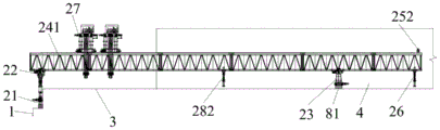
fig. 8 is a front view of the bridge girder erection machine after the bridge girder erection machine is assembled according to the bridge girder erection machine assembling method provided by the invention.
In the figure:
1. an abutment;
21. the front support leg transversely moves the track; 22. a front leg assembly; 23. a middle leg assembly; 241. a longitudinal guide beam assembly first section; 242. a longitudinal guide beam assembly second section; 243. a longitudinal guide beam assembly third section; 251. a front transverse connection; 252. rear transverse connection; 26. a rear landing leg assembly; 27. lifting the trolley assembly; 281. a front auxiliary ejector rod; 282. a middle auxiliary ejector rod;
3. a roadbed;
4. a tunnel;
5. erecting a place by using a truck crane;
6. a truck crane;
7. a bridge girder erection machine component stacking site;
81. a first crosstie; 82. and (7) a second sleeper.
Detailed Description
Reference will now be made in detail to embodiments of the present invention, examples of which are illustrated in the accompanying drawings, wherein like or similar reference numerals refer to the same or similar elements or elements having the same or similar function throughout. The embodiments described below with reference to the drawings are illustrative and intended to be illustrative of the invention and are not to be construed as limiting the invention.
In the description of the present invention, unless expressly stated or limited otherwise, the terms "connected," "connected," and "fixed" are to be construed broadly, e.g., as meaning permanently connected, removably connected, or integral to one another; can be mechanically or electrically connected; either directly or indirectly through intervening media, either internally or in any other relationship. The specific meanings of the above terms in the present invention can be understood in specific cases to those skilled in the art.
In the present invention, unless otherwise expressly stated or limited, "above" or "below" a first feature means that the first and second features are in direct contact, or that the first and second features are not in direct contact but are in contact with each other via another feature therebetween. Also, the first feature being "on," "above" and "over" the second feature includes the first feature being directly on and obliquely above the second feature, or merely indicating that the first feature is at a higher level than the second feature. A first feature being "under," "below," and "beneath" a second feature includes the first feature being directly under and obliquely below the second feature, or simply meaning that the first feature is at a lesser elevation than the second feature.
The technical scheme of the invention is further explained by the specific implementation mode in combination with the attached drawings.
The embodiment of the invention provides a bridge girder erection machine assembling method, which is used for bridge girder erection machine assembling construction on a narrow roadbed at a tunnel entrance, wherein the size of the bridge girder erection machine is 9m in height, 8m in width and 70m in length, and the spacing distance between a bridge and a tunnel is 16m.
Referring to fig. 1 to 8, an embodiment of the present invention provides a bridge girder erection machine assembling method, including:
s1: a front support leg transverse moving rail 21 is fixedly installed on the bridge abutment 1, a front support leg assembly 22 is fixedly installed on the front support leg transverse moving rail 21, the front support leg transverse moving rail 21 prevents the front support leg assembly 22 from transversely sliding or longitudinally toppling in the installation process of the bridge girder erection machine, and a middle support leg assembly 23 is fixedly installed on the roadbed 3 at a first set distance from the tunnel 4 opening, wherein the first set distance is 4m;
s2: the two longitudinal guide beam assembly first sections 241 are erected and installed on the middle leg assembly 23 and the front leg assembly 22 along the extending direction of the tunnel 4, wherein the end part of the longitudinal guide beam assembly first section 241 far away from the tunnel 4 extends out of the front leg assembly 22 by a second set distance, in this embodiment, the second set distance is 1.5m, and at this time, the weight of the bridge girder erection machine is borne by the front leg assembly 22 and the middle leg assembly 23 together;
s3: the rear supporting leg assembly 26 is arranged on the first section 241 of the longitudinal guide beam assembly close to the tunnel 4 according to the designed position, the lifting trolley assembly 27 is arranged on the first sections 241 of the two longitudinal guide beam assemblies, and the lifting trolley assembly 27 is used as the weight of the first sections 241 of the longitudinal guide beam assembly in the installation and longitudinal movement processes, so that the bridge girder erection machine can be prevented from overturning;
s4: mounting the next longitudinal guide beam assembly first section 241 at the end of the longitudinal guide beam assembly first section 241 furthest from the tunnel 4;
s5: moving all the installed first sections 241 of the longitudinal guide beam assemblies towards the direction close to the tunnel 4, realizing the movement of the first sections 241 of the longitudinal guide beam assemblies through upper-layer wheel boxes of the front support leg assembly 22 and the middle support leg assembly 23, wherein the moving length is equal to the length of the first sections 241 of the longitudinal guide beam assemblies installed in the step S4, keeping the position of the lifting trolley assembly 27 relative to the roadbed 3 unchanged while the first sections 241 of the longitudinal guide beam assemblies move, fixing the rear support leg assembly 26 with the ground, and simultaneously bearing the weight of the bridge girder erection machine by the front support leg assembly 22, the middle support leg assembly 23 and the rear support leg assembly 26;
s6: dismantling the middle support leg assembly 23, moving the middle support leg assembly 23 to a third set distance from the rear support leg assembly 26, fixing the middle support leg assembly 23 to the ground, wherein the third set distance is 2m in the embodiment, and releasing the fixing of the rear support leg assembly 26 to the ground, wherein the weight of the bridge girder erection machine is borne by the front support leg assembly 22 and the middle support leg assembly 23 together;
s7: and repeating S4 to S6 until the number of the first sections 241 of the longitudinal guide beam assembly is equal to the number required by the design, wherein the number of the first sections 241 of the longitudinal guide beam assembly is 6 in the embodiment.
The bridge girder erection machine assembling method provided by the invention is not limited by the space size of the tunnel, does not need to invest special hoisting equipment which can be used in the tunnel, can complete assembling construction of the bridge girder erection machine only by a truck crane, and has the advantages of small assembling difficulty, low risk and short construction period.
Referring to fig. 1, S0 is included before S1: the construction method comprises the steps of constructing a roadbed 3 and an abutment 1 in front of an opening of a tunnel 4, building a truck crane erecting site 5 on the side surfaces of the roadbed 3 and the abutment 1, placing a truck crane 6 in the truck crane erecting site 5, and building a bridge girder erection machine component stacking site 7 in front of the abutment 1 and the truck crane erecting site 5, so that an assembling site of the bridge girder erection machine is provided.
Referring to fig. 1, between S0 and S1 are included: the bridge girder erection machine components are placed in a bridge girder erection machine component stacking site 7 and comprise a front support leg transverse moving track 21, a front support leg assembly 22, a middle support leg assembly 23, a longitudinal guide beam assembly first section 241, a longitudinal guide beam assembly second section 242, a longitudinal guide beam assembly third section 243, a front cross link 251, a rear cross link 252, a rear support leg assembly 26, a lifting trolley assembly 27, a front auxiliary ejector rod 281 and a middle auxiliary ejector rod 282, and the bridge girder erection machine components are taken out from the bridge girder erection machine component stacking site 7 during subsequent assembly, so that the construction efficiency is improved.
Referring to fig. 3, in S3, the lifting trolley assembly 27 is located in the middle of the roadbed 3 in the longitudinal direction, and the lifting trolley assembly 27 serves as a ballast in the installation or movement process of the first segment 241 of the longitudinal guide beam assembly to prevent the bridge girder erection machine component from overturning, so that the ballast effect is better when the lifting trolley assembly 27 is located in the middle of the roadbed 3 in the longitudinal direction.
In S3, further comprising: a rear cross link 252 is installed on the first section 241 of the longitudinal guide beam assembly close to the tunnel 4, and the rear cross link 252 is used for connecting with a main beam of the bridge girder erection machine.
Referring to fig. 7, the installation process S5 and S6 of the middle longitudinal girder assembly first segment 241 of the all longitudinal girder assembly first segments 241 to the next longitudinal girder assembly first segment 241 of the middle longitudinal girder assembly first segment 241 includes: and middle auxiliary push rods 282 are arranged on the first sections 241 of the longitudinal guide beam assemblies in the middle according to designed positions, namely the middle auxiliary push rods 282 are arranged in the middle of the first sections 241 of all the longitudinal guide beam assemblies, and the middle auxiliary push rods 282 are used for bridging machine girders.
Referring to fig. 8, S8 is included after S7: and sequentially installing a second longitudinal guide beam assembly section 242 and a third longitudinal guide beam assembly section 243 at the end part of the finally installed first longitudinal guide beam assembly section 241, installing longitudinal guide beam assembly sections of different models according to specific construction requirements, only installing the first longitudinal guide beam assembly section 241 according to the specific construction requirements, and also installing other longitudinal guide beam assembly sections.
After S8, S9: and a front cross link 251 and a front auxiliary ejector rod 281 are arranged on a third section 243 of the longitudinal guide beam assembly, the front cross link 251 is used for being connected with a main beam of the bridge girder erection machine, and the front auxiliary ejector rod 281 is required to be used when the bridge girder erection machine passes through a hole.
Referring to fig. 2 to 8, in S1 and S6, the bottom of the middle leg assembly 23 is supported by the first sleeper 81 to fix the middle leg assembly 23 to the ground, and the middle leg assembly 23 is fixed to the ground or not fixed to the ground by supporting or removing the first sleeper 81.
Referring to fig. 5, in S5, the second sleeper 82 is supported at the bottom of the rear leg assembly 26 to fix the rear leg assembly 26 to the ground, and the rear leg assembly 26 is fixed to the ground or not fixed to the ground by supporting or removing the second sleeper 82, so that the structure is simple, the dismounting and mounting operations are convenient, and the cost is low.
The foregoing embodiments are merely illustrative of the principles and features of this invention, which is not limited to the above-described embodiments, but rather is susceptible to various changes and modifications without departing from the spirit and scope of the invention, which changes and modifications are within the scope of the invention as claimed. The scope of the invention is defined by the appended claims and equivalents thereof.
Claims (8)
1. A bridge girder erection machine assembling method is characterized by comprising the following steps:
s1: a front support leg transverse moving track (21) is fixedly installed on the bridge abutment (1), a front support leg assembly (22) is fixedly installed on the front support leg transverse moving track (21), and a middle support leg assembly (23) is fixedly installed on the ground, which is a first set distance away from the tunnel portal of the tunnel (4), on the roadbed (3);
s2: two longitudinal guide beam assembly first sections (241) are erected and mounted on the middle leg assembly (23) and the front leg assembly (22) along the extending direction of the tunnel (4), wherein the end of the longitudinal guide beam assembly first section (241) far away from the tunnel (4) extends out of the front leg assembly (22) for a second set distance;
s3: mounting rear leg assemblies (26) on the longitudinal guide beam assembly first sections (241) close to the tunnel (4), and mounting lifting trolley assemblies (27) on the two longitudinal guide beam assembly first sections (241);
s4: -mounting the next longitudinal guide beam assembly first section (241) at the end of the longitudinal guide beam assembly first section (241) furthest away from the tunnel (4);
s5: moving all the installed first longitudinal guide beam assembly sections (241) to the direction close to the tunnel (4) by the length equal to the length of the first longitudinal guide beam assembly sections (241) installed in the step S4, moving the first longitudinal guide beam assembly sections (241) while keeping the position of the lifting trolley assembly (27) relative to the roadbed (3) unchanged, and fixing the rear support leg assembly (26) with the ground;
s6: detaching the middle supporting leg assembly (23), moving the middle supporting leg assembly (23) to a third set distance away from the rear supporting leg assembly (26), fixing the middle supporting leg assembly (23) with the ground, and releasing the rear supporting leg assembly (26) from the ground;
s7: repeating S4-S6 until the number of the first sections (241) of the longitudinal guide beam assembly is equal to the number required by design;
before S1, S0: constructing the roadbed (3) and the abutment (1) in front of the tunnel opening of the tunnel (4), constructing a truck crane erecting site (5) on the side surfaces of the roadbed (3) and the abutment (1), placing a truck crane (6) in the truck crane erecting site (5), and constructing a bridge girder erection component stacking site (7) in front of the abutment (1) and the truck crane erecting site (5);
between S0 and S1 include: placing bridge girder erection machine components in the bridge girder erection machine component stacking site (7), wherein the bridge girder erection machine components comprise the front support leg transverse moving track (21), the front support leg assembly (22), the middle support leg assembly (23), the longitudinal guide beam assembly first section (241), the longitudinal guide beam assembly second section (242), the longitudinal guide beam assembly third section (243), a front transverse connection (251), a rear transverse connection (252), the rear support leg assembly (26), the lifting trolley assembly (27), a front auxiliary ejector rod (281) and a middle auxiliary ejector rod (282).
2. The bridge girder erection machine assembling method according to claim 1, wherein after S7, comprising S8: and sequentially installing the second longitudinal guide beam assembly section (242) and the third longitudinal guide beam assembly section (243) at the end of the first longitudinal guide beam assembly section (241) installed at the last time.
3. The bridge girder erection machine assembling method according to claim 2, wherein after S8, comprising S9: and the front cross link (251) and the front auxiliary mandril (281) are arranged on the third section (243) of the longitudinal guide beam assembly.
4. The bridge girder erection machine assembling method according to claim 1, further comprising, in S3: -mounting said rear crosspieces (252) on said longitudinal guide beam assembly first section (241) close to said tunnel (4).
5. The bridge girder erection machine assembling method according to claim 1, wherein selecting the middle auxiliary ram (282) in the middle longitudinal girder assembly first section (241) of all the longitudinal girder assembly first sections (241), and the installing process S5 and S6 of the longitudinal girder assembly first section (241) next to the middle longitudinal girder assembly first section (241) comprises: and the middle auxiliary mandril (282) is arranged on the first section (241) of the longitudinal guide beam assembly in the middle according to the designed position.
6. The bridge girder erection machine assembly method according to claim 1, wherein in S1 and S6, a first sleeper (81) is cushioned at the bottom of the center leg assembly (23) to fix the center leg assembly (23) on the ground.
7. A bridge girder erection method according to claim 1, wherein in S5, a second sleeper (82) is padded at the bottom of the rear leg assembly (26) to fix the rear leg assembly (26) on the ground.
8. A method of assembling a bridge girder erection machine according to claim 1, wherein in S3, the lifting trolley assembly (27) is located at a longitudinal middle portion of the roadbed (3).
Priority Applications (1)
| Application Number | Priority Date | Filing Date | Title |
|---|---|---|---|
| CN202110231011.0A CN113005911B (en) | 2021-03-02 | 2021-03-02 | Bridge girder erection machine assembling method |
Applications Claiming Priority (1)
| Application Number | Priority Date | Filing Date | Title |
|---|---|---|---|
| CN202110231011.0A CN113005911B (en) | 2021-03-02 | 2021-03-02 | Bridge girder erection machine assembling method |
Publications (2)
| Publication Number | Publication Date |
|---|---|
| CN113005911A CN113005911A (en) | 2021-06-22 |
| CN113005911B true CN113005911B (en) | 2023-03-24 |
Family
ID=76402483
Family Applications (1)
| Application Number | Title | Priority Date | Filing Date |
|---|---|---|---|
| CN202110231011.0A Active CN113005911B (en) | 2021-03-02 | 2021-03-02 | Bridge girder erection machine assembling method |
Country Status (1)
| Country | Link |
|---|---|
| CN (1) | CN113005911B (en) |
Families Citing this family (1)
| Publication number | Priority date | Publication date | Assignee | Title |
|---|---|---|---|---|
| CN117904977A (en) * | 2024-02-21 | 2024-04-19 | 广西路建工程集团有限公司 | Method for installing bridge girder erection machine in tunnel |
Family Cites Families (4)
| Publication number | Priority date | Publication date | Assignee | Title |
|---|---|---|---|---|
| US5511268A (en) * | 1994-08-08 | 1996-04-30 | The United States Of America As Represented By The Secretary Of Commerce | Construction of large structures by robotic crane placement of modular bridge sections |
| CN1880580A (en) * | 2006-01-18 | 2006-12-20 | 秦皇岛市北戴河通联路桥机械有限公司 | Bridging method by cooperation of temporary bridge and bridge girder erection machine at tunnel exit |
| CN102704407B (en) * | 2012-07-03 | 2013-04-17 | 中铁一局集团有限公司 | Construction method of lower guide beam type bridge-erecting crane passing through tunnel |
| CN204825525U (en) * | 2015-06-15 | 2015-12-02 | 中铁四局集团有限公司 | A modular steel sleeper for bridging tunnel entrances |
-
2021
- 2021-03-02 CN CN202110231011.0A patent/CN113005911B/en active Active
Also Published As
| Publication number | Publication date |
|---|---|
| CN113005911A (en) | 2021-06-22 |
Similar Documents
| Publication | Publication Date | Title |
|---|---|---|
| CN112726442A (en) | Construction method of large-span thin-wall concrete sound barrier pouring trolley | |
| CN114370006B (en) | Construction method for transferring bridge girder erection machine carried by girder transporting vehicle | |
| CN100497833C (en) | High-altitude framework type simple plate supporting machine | |
| CN113215994B (en) | Method for mounting bridge girder erection machine at tunnel outlet | |
| CN113005911A (en) | Bridge girder erection machine assembling method | |
| CN112211112A (en) | A kind of steel box girder installation method using double guide girder bridge erection machine on existing bridge | |
| CN110804958A (en) | A method for changing the frame of a whole-hole beam | |
| CN120575497A (en) | A method for constructing a tunnel-through bridge-erecting machine through holes and erecting beams in a confined space | |
| CN110777681A (en) | Whole hole roof beam trades a equipment | |
| CN117684456A (en) | Methods of erecting prefabricated beams in limited space | |
| CN119287793A (en) | Installation method of highway bridge erecting machine tunnel opening | |
| CN217174405U (en) | System for sliding arch rib segments on top surface of steel box girder | |
| CN117344980A (en) | A construction method of sliding support system for large-span steel trusses under complex support conditions | |
| CN214301283U (en) | A hanging construction platform under the beam flange plate | |
| CN216377240U (en) | Truss car for railway bridge deck system in steel truss girder | |
| KR102275474B1 (en) | Construction method of structures on tramway catenary | |
| CN110626943B (en) | Special chassis of inverted gantry crane for single-line T-beam bridge and mounting method | |
| CN112376437B (en) | Steel beam beam-carrying crane suspension assembly equipment and construction method | |
| CN213952287U (en) | A truss car device for the reconstruction and expansion of existing elevated operation subway stations | |
| CN211772946U (en) | A kind of whole hole beam rack changing equipment | |
| CN102146798A (en) | Arch ring lining trolley for additionally building open cut tunnel on electrified railway business line and construction method of arch ring lining trolley | |
| CN110562287B (en) | Quick jacking and resetting device for derailing vehicle and using method of quick jacking and resetting device | |
| CN210368664U (en) | Wide-body bridge girder erection machine | |
| CN210738584U (en) | Space rigid frame trolley suitable for existing line crossing construction | |
| CN114751343A (en) | An aerial work platform for railway tunnel maintenance |
Legal Events
| Date | Code | Title | Description |
|---|---|---|---|
| PB01 | Publication | ||
| PB01 | Publication | ||
| SE01 | Entry into force of request for substantive examination | ||
| SE01 | Entry into force of request for substantive examination | ||
| GR01 | Patent grant | ||
| GR01 | Patent grant |