Integrated sucker rod automatic slip and operation process
Technical Field
The invention relates to the technical field of workover sucker rod auxiliary devices and operation processes, in particular to an integrated sucker rod automatic slip and an operation process.
Background
The well repair operation is the most common form of oil field, and is divided into minor repair operation and major repair operation, wherein the minor repair operation mainly comprises operations of pump inspection, process change, sand washing and the like by lifting and lowering a transport pipe column to complete the operation task. At present, the main flow sucker rod operation process is characterized in that: the method is completed by machinery and manpower. The pumping rod has the advantages that the elevator is driven to be a main part through the hook, at least 2 elevators circulate in the center of the hook and the well mouth, one of the two elevators is used as the elevator, the other elevator is used as the slip, the two slips are completely transported and hooked by manpower, after the slips are clamped, the hydraulic tong needs to be manually pushed to the position above the slip, the screwing-in and unscrewing actions of the pumping rod are completed, and after the screwing-out is completed, the hydraulic tong is pushed back to the original position. The hook moves down, and after artifical supplementary sucker rod was placed on the catwalk, the slips on the hook was pulled down to the well head workman, and the elevator that will be located at the well head hangs on the hook, and the hook shifts up in order to accomplish the sucker rod flow of next flow. In the whole process of taking off and putting down the sucker rod, the problems of more occupied workers, high labor intensity, poor outdoor construction environment, high safety risk and the like exist.
In order to realize the automation of the minor repair operation of the sucker rod, the operation flow of the minor repair operation of the sucker rod needs to be changed. The oil field well repairing process (patent No. ZL 202011048977.2) for realizing automation of pumping rod realizes automation of minor repair operation of the pumping rod, wherein the pumping rod is lifted and lowered by adopting a 'one-hoisting-one-clamping' structure, namely, the elevator and the slips are matched with each other to finish the lifting and lowering operation of the pumping rod, the process realizes the automation of the minor repair operation of the pumping rod, the process basically does not need manual intervention, the labor intensity of workers is reduced, and the working efficiency is increased.
The catwalk, the power slip and the automatic elevator related by the invention are issued by Kangbei petroleum company of the team and the technical transformation enterprise, and comprise an integrated guide type vertical operation workover catwalk with well head positioning and a using method (ZL202010998186. X), an automatic elevator of a sucker rod for oil field workover operation and a using method (ZL202073476. X), and an automatic elevator of the sucker rod capable of realizing the automatic alignment function and a using method (202011573843.2), or are improved and simplified on the basis of the patents. The invention provides an integrated sucker rod automatic slip and an operation process by reforming the existing slips of an oil field according to the patents.
Disclosure of Invention
The invention aims to provide an integrated automatic slips for sucker rods and an operation process, aiming at the defects in the prior art, the integrated automatic slips for sucker rods can clamp/support the flange of the sucker rod, can adapt to the clamping/support of the sizes of the sucker rods with different specifications by replacing a slip core, further integrates a tripping clamp on the sucker rod on the slip, forms a new mode of 'one hanging and one clamping' with an automatic elevator, and is a main component for realizing the mechanized operation of a wellhead of the sucker rod.
The invention provides an integrated automatic slip for a sucker rod, which adopts the technical scheme that: the device comprises a sucker rod clamping module and an upper shackle module, wherein the sucker rod clamping module and the upper shackle module are connected through a V-shaped block; the sucker rod clamping module comprises a quick-change slip core, a quick-change locking block, a slip base upper supporting plate, a slip base, a locking block base upper supporting plate, a locking block base, an inductive sensor, a heavy-load guide rail slide block driving module, a heavy-load guide rail supporting plate and a small four-way connecting flange, wherein the slip base upper supporting plate and the locking block base upper supporting plate are respectively arranged above the slip base and the locking block base and jointly form a bearing plane of the automatic elevator, the quick-change slip core and the quick-change locking block are respectively arranged on the slip base and the locking block base, the quick-change slip core, the quick-change locking block, the slip base and the locking block base jointly form a sucker rod clamping mechanism, the locking block base and the slip base are respectively arranged on two sliders on the heavy-load guide rail and can move along with the sliders, and the heavy-load guide rail supporting plate is connected with the heavy-load guide rail through bolts, the heavy-duty guide rail sliding block driving module comprises a stepping motor, a motor mounting seat, a split screw nut pair and a T-shaped block, wherein the motor mounting seat is connected with a heavy-duty guide rail supporting plate through a bolt;
the upper shackle module consists of upper shackle tongs, a dust-free linear guide rail, an upper shackle tongs supporting plate and an industrial electric push rod, wherein the dust-free linear guide rail is connected with the upper shackle tongs supporting plate through a bolt, the upper shackle tongs are installed on the dust-free linear guide rail, the dust-free linear guide rail can drive the upper shackle tongs to move towards a well mouth and move away from the well mouth, and the industrial electric push rod is installed below the upper shackle tongs supporting plate.
Preferably, the quick-change slip core and the quick-change locking block are respectively installed on the slip base and the locking block base according to the size and shape design of the sucker rod flange, and the corresponding slip core is required to be replaced to clamp the sucker rod flanges with different sizes when the sucker rods with different sizes are clamped.
Preferably, the quick-change slip core and the quick-change locking block jointly form a closed sucker rod flange bearing surface, and the quick-change locking block is used for ensuring that the sucker rod does not shift in the process of screwing off and the other processes.
Preferably, the driving structure of the slip base and the locking block base is a split screw nut pair, and the slip base and the locking block base can be quickly combined or separated by using one stepping motor.
Preferably, install induction type sensor on the above-mentioned quick change lock block, after the quick change slips core contact on sucker rod flange and the slips base, the dustless linear guide after triggering induction type sensor drives and goes up the break-out pincers and remove to the well head and accomplish and go up the action of breaking out, after the quick change slips core on sucker rod flange and the slips base breaks away from, triggers heavy load guide rail slider drive module drive slips base and lock block base quick separation.
Preferably, the upper shackle module and the sucker rod clamping module are connected through two V-shaped blocks, the directions of the two V-shaped blocks are perpendicular to each other, the upper shackle module and the sucker rod clamping module are connected together, and an upper shackle clamp in the upper shackle module is positioned through a slip base in the oil pumping clamping module and used for ensuring that a main clamp and a back clamp of the upper shackle clamp accurately clamp a wrench side of two sucker rods.
Preferably, above-mentioned industry electric putter begins to stretch out until contacting ground after last break-out module and sucker rod centre gripping module are connected, guarantees that the break-out pincers backup pad does not take place the bending and then guarantees that dustless linear guide can accomplish smoothly to the well head motion and keep away from the well head motion.
The invention provides an operation process of an integrated sucker rod automatic slip, which comprises the following steps:
when the sucker rod is lifted, the hook drives the elevator to lift the upper sucker rod out of the sucker rod slip, the induction type sensor is triggered, the heavy-load guide rail slide block driving module drives the slip base and the locking block base to be quickly separated, and at the moment, the slip finishes the opening action; the distance from the flange of the lower sucker rod to the position 200 plus 500mm above the quick-change slip core is exceeded, the hook stops moving upwards under the control of a large class driver or a program, the heavy-load guide rail slide block driving module drives the slip base and the locking block base to approach quickly, the slip is closed at the moment, the hook moves downwards to drive the flange of the sucker rod to contact with the quick-change slip core on the slip base to trigger the induction type sensor, the dust-free linear guide rail drives the upper breaking pliers to move towards the well mouth, the positioning block is triggered, the back pliers and the movable pliers of the upper breaking pliers of the sucker rod are aligned with the center of the well mouth, the upper breaking action is completed, and the upper breaking pliers return after the upper breaking action is completed; after the catwalk grabs the last sucker rod and carries on the pipe rack, a flow action of playing the sucker rod is accomplished, and the big hook drives the elevator and moves down and prepare to carry out next sucker rod process of playing.
Compared with the prior art, the invention has the following beneficial effects:
on one hand, the invention forms a new mode of 'one hanging and one clamping', the original double hanging clamps are not used for circulation, wellhead workers do not need to carry the hanging clamps, meanwhile, the sucker rod slips of the slip core are quickly changed to integrate the upper shackle module and the sucker rod clamping module, the wellhead workers do not need to move upper shackle tongs to the wellhead during shackle loading, and the working strength of the wellhead workers is reduced;
on the other hand, the bearing part of the invention is a slip base, is designed according to the size and shape of the flange of the sucker rod, is arranged on a slide block of a heavy-load guide rail, is clamped into a rod body of the sucker rod through translation along the guide rail, and falls down to realize clamping/bearing of the flange of the sucker rod, and has strong bearing capacity and simple and reliable operation; the sucker rod is further limited to be separated through the locking block, and the operation safety is improved;
moreover, the invention can form a set of automatic sucker rod minor repair operation machine by combining the power catwalk, the automatic elevator and other well repair equipment, and has important significance for realizing the automation and the intellectualization of the sucker rod minor repair operation.
Drawings
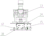
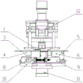
FIG. 1 is a front view of the present invention;
FIG. 2 is a left side view of the present invention;
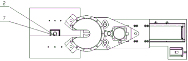
FIG. 3 is a top view of the present invention;
FIG. 4 is a schematic structural view of a heavy duty rail drive module according to the present invention;
FIG. 5 is a schematic view of the structure of two V-shaped blocks in the present invention;
FIG. 6 is a schematic view of the installation of two V-blocks in the present invention;
FIG. 7 is a schematic view of the installation of the present invention;
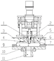
FIG. 8 is a sectional view showing the working state of the sucker rod clamping module according to the present invention;
FIG. 9 is a sectional view of the upper shackle module of the present invention in an operative condition;
FIG. 10 is a schematic view of the open state of the sucker rod clamping module of the present invention;
FIG. 11 is a structural schematic view of the upper shackle module in a non-operating state in accordance with the present invention;
FIG. 12 is a schematic view of a single-sided configuration of a sucker rod;
in the upper diagram: the slip quick-change device comprises a quick-change slip core 1, a quick-change locking block 2, a slip base upper supporting plate 3, a slip base 4, a locking block base upper supporting plate 5, a locking block base 6, an induction type sensor 7, a heavy-load guide rail slide block driving module 8, a heavy-load guide rail 9, a heavy-load guide rail supporting plate 10, a small four-way connecting flange 11, a V-shaped block 12, an upper shackle clamp 13, a dust-free linear guide rail 14, an upper shackle clamp supporting plate 15 and an industrial electric push rod 16;
the device comprises a stepping motor 8.1, a motor mounting seat 8.2, a split lead screw nut pair 8.3, a T-shaped block 8.4, an external thread 17.1, an unloading groove 17.2, a thrust surface shoulder 17.3, a wrench square 17.4, a flange 17.5 and an arc transition area 17.6.
Detailed Description
The preferred embodiments of the present invention will be described in conjunction with the accompanying drawings, and it will be understood that they are described herein for the purpose of illustration and explanation and not limitation.
Embodiment 1, referring to fig. 1 to 7, the integrated sucker rod automatic slip according to the present invention comprises a sucker rod clamping module and an upper shackle module, wherein the sucker rod clamping module and the upper shackle module are connected by two V-shaped blocks 12;
the sucker rod clamping module comprises a quick-change slip core 1, a quick-change locking block 2, a slip base upper supporting plate 3, a slip base 4, a locking block base upper supporting plate 5, a locking block base 6, an induction type sensor 7, a heavy-load guide rail slide block driving module 8, a heavy-load guide rail 9, a heavy-load guide rail supporting plate 10 and a small four-way connecting flange 11, wherein the slip base upper supporting plate 3 and the locking block base upper supporting plate 5 are respectively arranged above the slip base 4 and the locking block base 6 and jointly form a bearing plane of the automatic elevator, the slip core 1 and the quick-change locking block 2 are respectively arranged on the slip base 4 and the locking block base 6, the quick-change slip core 1, the locking quick-change block 2, the slip base 4 and the locking block base 6 jointly form a sucker rod clamping mechanism, the locking block base 6 and the slip base 4 are respectively arranged on two sliders on the heavy-load guide rail 9, the clamping device can move along with a sliding block, a heavy-load guide rail 9 is connected with a heavy-load guide rail supporting plate 10 through a bolt, a heavy-load guide rail sliding block driving module 8 is composed of a stepping motor 8.1, a motor mounting seat 8.2, a split lead screw nut pair 8.3 and a T-shaped block 8.4, the motor mounting seat 8.2 is connected with the heavy-load guide rail supporting plate 10 through a bolt, the stepping motor 8.1 is mounted on the motor mounting seat 8.2, an output shaft of the stepping motor 8.1 is connected with the split lead screw nut pair 8.3, the nut in the split lead screw nut pair 8.3 is driven to move in the opposite direction by rotation of the stepping motor 8.1, the nut in the split lead screw nut pair 8.3 is connected with the T-shaped block 8.4 through a bolt, the T-shaped block 8.4 is simultaneously connected with a sliding block in the heavy-load guide rail 9, the nut moves to drive the sliding block on the heavy-load guide rail 9 to move, opening and closing actions of a slip are completed, and clamping of a sucker rod flange 17.5 is realized.
The upper shackle module is composed of upper shackle clamps 13, a dust-free linear guide rail 14, an upper shackle clamp supporting plate 15 and an industrial electric push rod 16, wherein the dust-free linear guide rail 14 is connected with the upper shackle clamp supporting plate 15 through bolts, the upper shackle clamps 13 are installed on the dust-free linear guide rail 14, the dust-free linear guide rail 14 can drive the upper shackle clamps 13 to move towards a well mouth and move away from the well mouth, and the industrial electric push rod 16 is installed below the upper shackle clamp supporting plate 15.
Wherein, quick change slips core 1 and quick change locking block 2 are installed respectively on slips base 4 and locking block base 6 according to sucker rod flange 17.5 size shape design, when the not unidimensional sucker rod of centre gripping, need change corresponding slips core with the flange 17.5 of the not unidimensional sucker rod of centre gripping.
In addition, the quick-change slip core 1 and the quick-change locking block 2 jointly form a closed sucker rod flange bearing surface, and the quick-change locking block 2 ensures that the sucker rod does not shift in the processes of screwing off and the other processes so as to reduce the incidence rate of accidents; the end of the sucker rod comprises an external thread 17.1, an unloading groove 17.2, a thrust surface shoulder 17.3, a wrench square 17.4, a flange 17.5 and an arc transition zone 17.6.
Furthermore, the driving structure of the slip base 4 and the locking block base 6 is a split screw nut pair 8.3, the slip base 4 and the locking block base 6 can be quickly combined or separated by using one stepping motor 8.1, and other devices and mechanisms capable of quickly combining or separating the slip base 4 and the locking block base 6 are all within the protection scope of the patent.
The quick-change slip type pump is characterized in that an induction type sensor 7 is installed on the quick-change locking block 2, after a sucker rod flange 17.5 is in contact with a quick-change slip core 1 on the slip base 4, a dust-free linear guide rail 14 drives an upper shackle clamp 13 to move towards a well head to complete an upper shackle action after the induction type sensor 7 is triggered, and after the sucker rod flange 17.5 is separated from the quick-change slip core 1 on the slip base 4, a heavy-load guide rail slide block driving module 8 is triggered to drive the slip base 4 and the locking block base 6 to be quickly separated.
In addition, the upper breaking module and the sucker rod clamping module are connected through two V-shaped blocks 12, the upper breaking module and the sucker rod clamping module are connected together, an upper breaking clamp 13 in the upper breaking module is positioned according to a slip base 4 in the sucker rod clamping module, and a wrench square 17.4 for accurately clamping two sucker rods by a main clamp and a back clamp of the upper breaking clamp 13 is ensured.
Specifically, the directions of the two V-shaped blocks 12 are perpendicular to each other, so that the accurate connection of the upper shackle module to the sucker rod clamping module is ensured, and the purpose of accurate positioning of the upper shackle module is achieved.
The industrial electric push rod 16 of the invention starts to extend until contacting the ground after the upper shackle module and the sucker rod clamping module are connected, thereby ensuring that the upper shackle clamp support plate 15 is not bent and ensuring that the dust-free linear guide rail 14 can smoothly complete the movement towards the well mouth and the movement away from the well mouth.
The invention provides an integrated sucker rod automatic slip and an operation process, which comprises the following processes:
referring to fig. 6-7, in the minor repair operation process of the sucker rod, a sucker rod clamping module in a sucker rod slip of the quick-change slip core 1 is arranged on a small four-way of a well head and is fixed by a clamp; after the sucker rod clamping module is installed, a large class driver controls the hook to drive the upper shackle module to a set position, and the V-shaped groove on the upper shackle clamp supporting plate 15 is ensured to be matched with the V-shaped block 12 on the sucker rod clamping module. The directions of the two V-shaped blocks 12 are mutually vertical, after the V-shaped grooves on the support plate 15 of the upper shackle tongs are matched with the V-shaped blocks 12 on the clamping modules of the sucker rods, the upper shackle modules are guaranteed not to deviate relative to the clamping modules of the sucker rods, and meanwhile, the main tongs and the back tongs of the upper shackle tongs 13 are guaranteed to accurately clamp the wrench sides 17.4 of the two sucker rods. After the make-up and break-out module is completed, the industrial electric push rod 16 extends until contacting the ground, and the support of the make-up and break-out module is completed.
Referring to fig. 8, 10 and 11, in the process of pumping up the sucker rod, the sucker rod clamping module clamps the flange 17.5 of the sucker rod, and the upper breaking module is in the non-working position. The hook drives the automatic elevator to move down to clamp the wrench square 17.4 of the sucker rod, and after accurate clamping, a large driver or a program controls the hook to drive the elevator to move up. After the sucker rod moves up for a certain distance, the induction type sensor 7 is triggered, a signal is sent to the induction type sensor 7 to the heavy-load guide rail slide block driving module 8, the nut in the split lead screw nut pair 8.3 is driven to move in the opposite direction by the rotation of the stepping motor 8.1, the slip base 4 and the locking block base 6 which are installed on the heavy-load guide rail 9 slide block are quickly separated, and the opening of the slip of the sucker rod with the quick-change slip core 1 is realized.
Referring to fig. 8-12, after the automatic elevator lifts the sucker rod to a specified distance, the flange 17.5 of the lower sucker rod appears above the supporting plate 3 on the slip base and the supporting plate 5 on the locking block base, the reverse rotation of the stepping motor 8.1 drives the nuts in the split lead screw nut pair 8.3 to move in opposite directions, the slip base 4 and the locking block base 6 installed on the slide block of the heavy-duty guide rail 9 approach quickly, and the closing of the sucker rod slip of the quick-change slip core 1 is realized. The automatic elevator lowers the sucker rod to ensure that the sucker rod clamping module clamps the flange 17.5 of the lower sucker rod, the manipulator on the power catwalk grabs the sucker rod, and the elevator is separated from the sucker rod to return to the initial position. Trigger inductive sensor 7 this moment, inductive sensor 7 signals gives the dustless linear guide 14 in the module of breaking out on, the pincers 13 of breaking out on dustless linear guide 14 drives and removes to the well head, the locating piece is triggered, the well head center is adjusted well to 13 back-ups and the main pincers of the pincers of breaking out on, 17.4 of the spanner side of sucker rod under the accurate centre gripping of back-ups of pincers 13 of breaking out on, 17.4 of the spanner side of sucker rod (the action of breaking out on main pincers centre gripping sucker rod coupling also can be accomplished), the action of breaking out on the sucker rod begins to carry out.
After the action of the upper shackle of the sucker rod is completed, the power catwalk conveys the sucker rod to the pipe rack, the upper shackle clamp module returns to the initial position (namely the position of the non-working state), the automatic elevator moves downwards, the supporting legs at the lower end of the elevator and the slip base of the sucker rod slip of the quick-change slip core 1 are in surface contact with the supporting plate 3 and the supporting plate 5 on the locking block base, and the action of once lifting the sucker rod is completed.
It is worth mentioning that in the process of lifting the sucker rod, when the diameter of the sucker rod is different, the quick-change slip core 1 and the quick-change locking block 2 need to be replaced to adapt to the surfaces of the flanges 17.5 of the sucker rod with different sizes.
Supplementary notes, this device is installed on the little cross of well head, specifically is: the small four-way connecting flange 11 is connected to the small four-way of the wellhead through a standard clamp, and the installation is convenient and reliable.
The lower sucker rod and the upper sucker rod are reversible processes, and therefore, the description is omitted here.
The above description is only a few of the preferred embodiments of the present invention, and any person skilled in the art may modify the above-described embodiments or modify them into equivalent ones. Therefore, the technical solution according to the present invention is subject to corresponding simple modifications or equivalent changes, as far as the scope of the present invention is claimed.