Textile cloth drying equipment
Technical Field
The invention relates to the technical field of textile drying, in particular to textile cloth drying equipment.
Background
The weaving principle is a general name taken from spinning and weaving, but with the continuous development and improvement of a weaving knowledge system and a subject system, particularly after non-woven textile materials, three-dimensional compound weaving and other technologies are produced, the weaving is not only traditional spinning and weaving, but also comprises a non-woven fabric technology, a three-dimensional weaving technology, an electrostatic nano-web forming technology and the like. The spinning is roughly divided into two procedures of spinning and weaving. After the cloth is woven, cleaning equipment is needed to clean the cloth to remove cloth hair on the cloth, and then the cloth is dried through drying equipment. The textile drying equipment refers to a combination of a series of mechanical equipment for drying moisture or other liquid on the surface of a textile product by a certain technical means. A dryer is one of indispensable production equipment in textile production. In the textile industry, a dryer is mainly used for drying and fixing textile fabrics, and the heating and drying modes mainly comprise a hot air heating and drying mode and an electric heating and drying mode.
At present, the tradition removes partly with moisture before to weaving cloth drying and puts into the drying oven again, and this method process is many, has increased the hand labor volume, wastes time and energy, and wastes a large amount of time and resource, increases manufacturing cost to drying efficiency is low, direct influence production efficiency, and the unable cyclic utilization that absorbs of heat causes the wasting of resources, has reduced performance.
Disclosure of Invention
Technical problem to be solved
Aiming at the defects of the prior art, the invention provides a textile cloth drying device, which solves the problems that the conventional method has many processes, increases the amount of manual labor, wastes time and labor, wastes a large amount of time and resources, increases the production cost, has low drying efficiency, directly influences the production efficiency, cannot absorb heat for cyclic utilization, causes resource waste and reduces the use performance because a part of water is removed before the textile cloth is dried.
(II) technical scheme
In order to achieve the purpose, the invention is realized by the following technical scheme: a textile cloth drying device comprises a drying box, wherein a lifting mechanism, a drying device, a heater, a curve pipe, a water collector and a gas dryer are arranged inside the drying box, the lifting mechanism is arranged at the center of the top of the inner wall of the drying box, the drying device is arranged between the bottom of the inner wall of the drying box and two sides corresponding to the bottom of the lifting mechanism, the heater is fixed on one side of the inner wall of the drying box and is close to the top, the air outlet end of the heater is communicated with the air inlet end of the drying device, one end of the curved line pipe is communicated with the air outlet end of the drying device, the water collector is arranged at the bottom of the curved line pipe, the gas dryer is fixed on one side of the inner wall of the drying box and is close to the bottom, the air inlet end of the gas dryer is communicated with one end, away from the drying device, of the curved pipe, and the air outlet end of the gas dryer is communicated with the air inlet end of the heater.
Preferably, drying device is equipped with except that water roller device, connecting pipe, dry head device, except that the water roller device passes through the support setting in the inner wall bottom of drying cabinet, the surface at elevating system is fixed to the connecting pipe, dry head device is fixed and the intercommunication is in the bottom of connecting pipe, the connecting pipe is kept away from between the one end of dry head device and the heater through the hose intercommunication, dry head device and the cooperation of removing between the water roller device are connected.
Preferably, the dewatering roller device is equipped with roll body, inner chamber, hole that leaks, scrapes the water installation, the roll body rotates to be connected on the support, the inside central point that the roll body was seted up to the inner chamber puts, the hole that leaks is seted up on the surface of roll body and communicates with the inner chamber, it sets up in the inside of inner chamber and is located the surface position of roll body to scrape the water installation.
Preferably, the water scraping device is provided with a scraper device, an arc elastic piece and an elastic water bag, the scraper device is connected inside the roller body in a sliding mode and is close to the surface position, the arc elastic piece is arranged between the two sides of the inner wall of the roller body corresponding to the bottom edge of the surface of the scraper device, and the elastic water bag is arranged between the two sides of the inner wall of the roller body corresponding to the surface of the scraper device.
Preferably, the water inlet end of the elastic water bag is provided with a water inlet one-way valve, and the water outlet end of the elastic water bag is provided with a water outlet one-way valve.
Preferably, the scraper device is provided with a scraper body, a diversion trench and a water suction hole, the scraper body is connected with the roller body in a sliding manner, the diversion trench is arranged on one side of the surface of the scraper body, the water suction hole is arranged in the scraper body and is located at the top end, and the water suction hole is communicated with the water inlet end of the elastic water bag.
Preferably, the drying head device is provided with a base block, an arc-shaped gradual change groove and a drying hole, the base block is fixed at the bottom end of the connecting pipe, the arc-shaped gradual change groove is formed in the bottom of the base block, and the drying hole is formed in the base block and is positioned in the arc-shaped gradual change groove and communicated with the connecting pipe.
(III) advantageous effects
The invention provides a textile cloth drying device. The method has the following beneficial effects:
(one), this weaving cloth drying equipment through drying cabinet, elevating system, drying device, heater, curvilinear pipe, receipts hydrophone, gas desicator, can in time retrieve the heat and recycle, has reduced the heat and has lost, and the make full use of resource reduces the energy consumption, and is simultaneously quick even to the cloth drying, has shortened drying time, has reduced production cycle, has alleviateed the amount of labour, and labour saving and time saving has improved production efficiency.
(II), this weaving cloth drying equipment through dewatering roller device, connecting pipe, dry head device, sets up multiunit dewatering roller device and dry head device in the inside of drying cabinet, and uses together in the cooperation between dewatering roller device and the dry head device, has realized progressively dry effect, will dewater simultaneously and dry effectual combination together, does not need artifical dewatering, has alleviateed the amount of manual labor, the assistance-time that has significantly reduced, has promoted drying effect, whole structure links together.
(III), this weaving cloth drying equipment through dry head device, roll body, inner chamber, scrape the water installation, when the roll body is rotating, the roll body extrudees the cloth with dry head device, extrudees water, scrapes the water installation simultaneously and under the rotation circumstances, constantly strikes off the water on the cloth, and then utilizes multiple method to remove the water simultaneously for it is convenient fast to go out water, and is efficient.
(IV), this weaving cloth drying equipment through setting up heater, curved line pipe, the hole that leaks, utilizes heater, curved line pipe, the intercommunication between the hole that leaks for steam carries out cyclic utilization, reduces calorific loss, has reduced the energy consumption, and the water that the hole that leaks simultaneously struck off in time discharges, is favorable to drying work, and then makes the hole that leaks realize multiple functions, has improved performance.
(five), this weaving cloth drying equipment, through scraper means, the arc elastic component, the elasticity water pocket, arc gradual change recess, when dewatering roller device rotates, scraper means also rotates thereupon, and under the effect that the direction of arc gradual change recess was pressed, make scraper means when scraping water to the cloth, also stretch the elasticity water pocket, and absorb water through scraper means self, and then through having increased the dewatering mode, can carry out quick dewatering, when scraper means breaks away from dry head device, reset under the effect of arc elastic component, make the elasticity water pocket volume reduce, discharge inside water, and then under reciprocating circulation, remove water fast, be favorable to rapid draing.
(six), this weaving cloth drying equipment, through scraper blade body, guiding gutter, the hole that absorbs water, when scraper means is when rotating, can in time strike off the water on the cloth, the guiding gutter has the effect of water conservancy diversion this moment, is favorable to water in time to flow out to a plurality of holes that absorb water begin to absorb water simultaneously under the suction effect of elasticity water pocket, and then remove the water, make whole device realize multiple dewatering mode, thereby be favorable to blowing the water fast with the cloth, be convenient for dry.
(seventh), this weaving cloth drying equipment, through dewatering roller device, the base block, arc gradual change recess, drying hole, when dewatering roller device is when rotating, and carry out the dewatering under the effect of arc gradual change recess direction, can hug closely the cloth between base block and dewatering roller device simultaneously, through the extrusion, further favourable dewatering, and evenly distributed's dry steam of dry hole output, with cloth fast drying, and whole structure links together, and no isolated existence, safe and reliable has improved performance.
Drawings
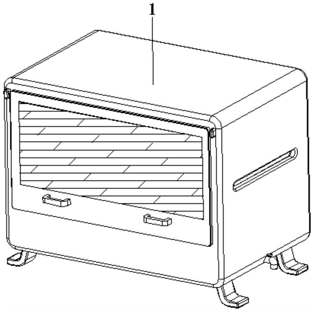
FIG. 1 is a schematic view of the overall structure of a textile cloth drying apparatus according to the present invention;
FIG. 2 is a schematic view of the internal structure of the textile cloth drying apparatus of the present invention;
FIG. 3 is a schematic structural view of a drying device of the textile cloth drying apparatus of the present invention;
FIG. 4 is a schematic structural diagram of a dewatering roller device of the textile cloth drying equipment;
FIG. 5 is a schematic view showing a wiper device of a textile fabric drying apparatus according to the present invention;
FIG. 6 is a structural schematic view of a scraper device of the textile cloth drying equipment;
FIG. 7 is a schematic structural diagram of a drying head device of the textile cloth drying equipment.
In the figure: the device comprises a drying box 1, a lifting mechanism 2, a drying device 3, a heater 4, a curve pipe 5, a water collector 6, a gas dryer 7, a water removing roller device 31, a connecting pipe 32, a drying head device 33, a roller body 311, an inner cavity 312, a water leakage hole 313, a water scraping device 314, a base block 331, an arc gradual change groove 332, a drying hole 333, a1 scraper device, an a2 arc elastic piece, a3 elastic water bag, a01 water inlet check valve, a02 water outlet check valve, b1 scraper body, a b2 diversion trench and a b3 water suction hole.
Detailed Description
The technical solutions in the embodiments of the present invention will be clearly and completely described below with reference to the drawings in the embodiments of the present invention, and it is obvious that the described embodiments are only a part of the embodiments of the present invention, and not all of the embodiments. All other embodiments, which can be derived by a person skilled in the art from the embodiments given herein without making any creative effort, shall fall within the protection scope of the present invention.
The first embodiment is as follows:
referring to fig. 1-7, the present invention provides a technical solution: a textile cloth drying device comprises a drying box 1, wherein a lifting mechanism 2, a drying device 3, a heater 4, a curved line pipe 5, a water collector 6 and a gas dryer 7 are arranged inside the drying box 1, the lifting mechanism 2 is arranged at the central position of the top of the inner wall of the drying box 1, the drying device 3 is arranged between the bottom of the inner wall of the drying box 1 and two sides corresponding to the bottom of the lifting mechanism 2, the heater 4 is fixed on one side of the inner wall of the drying box 1 and is close to the top, the air outlet end of the heater 4 is communicated with the air inlet end of the drying device 3, one end of the curved line pipe 5 is communicated with the air outlet end of the drying device 3, the water collector 6 is arranged at the bottom of the curved line pipe 5, the gas dryer 7 is fixed on one side of the inner wall of the drying box 1 and is close to the bottom, the air inlet end of the gas dryer 7 is communicated with one end of the curved line pipe 5, which is far away from the, the drying device can timely recycle heat, reduces heat loss, fully utilizes resources, reduces energy consumption, simultaneously dries cloth quickly and uniformly, shortens drying time, reduces production period, reduces labor amount, saves time and labor, and improves production efficiency.
Drying device 3 is equipped with except that water roller device 31, connecting pipe 32, dry head device 33, it sets up the inner wall bottom at drying cabinet 1 to remove water roller device 31 through the support, the surface at elevating system 2 is fixed to connecting pipe 32, dry head device 33 is fixed and the bottom of intercommunication at connecting pipe 32, connecting pipe 32 is kept away from between dry head device 33's one end and the heater 4 through the hose intercommunication, it is connected to cooperate between dry head device 33 and the removal water roller device 31, it uses together to cooperate between removal water roller device 31 and the dry head device 33, progressively dry effect has been realized, simultaneously with the effectual combination of dewatering and stoving together, do not need artifical dewatering, the amount of labour has been alleviateed, the assistance-time has been greatly reduced, drying effect has been promoted.
Dewatering roller device 31 is equipped with roll body 311, inner chamber 312, water leakage hole 313, scrape water installation 314, roll body 311 rotates to be connected on the support, the inside central point that roll body 311 was seted up to inner chamber 312 is put, water leakage hole 313 is seted up on the surface of roll body 311 and is communicate with inner chamber 312, scrape water installation 314 and set up in the inside of inner chamber 312 and be located the surface position of roll body 311, when roll body 311 is rotating, roll body 311 extrudes the cloth with drying head device 33, extrude water, scrape water installation 314 simultaneously under the rotation condition, constantly scrape the water on the cloth, and then utilize multiple method to remove the water simultaneously, make it convenient fast to go out water, high efficiency.
The wiper device 314 is provided with a scraper device a1, an arc-shaped elastic piece a2 and an elastic water bag a3, wherein the scraper device a1 is slidably connected inside the roller body 311 and is close to the surface, the arc-shaped elastic piece a2 is arranged between the inner wall of the roller body 311 and the two sides corresponding to the bottom edge of the surface of the scraper device a1, the elastic water bag a3 is arranged between the inner wall of the roller body 311 and the two sides corresponding to the surface of the scraper device a1, when the dewatering roller device 31 rotates, the scraper device a1 also rotates along with the roller, under the guiding and pressing action of the arc-shaped gradual change groove 332, the scraper device a1 also stretches the elastic water bag a3 when wiping the cloth, absorbs water through the scraper device a1, and further, the dewatering mode is increased, the quick dewatering can be carried out, when the scraper device a1 is separated from the drying head device 33, the elastic water bag a2 is reset under the action of the arc-shaped elastic piece, the internal water is discharged and then circulated to remove water quickly, which is beneficial to quick drying.
Scraper means a1 is equipped with scraper body b1, guiding gutter b2, water absorption hole b3, sliding connection between scraper body b1 and roll body 311, guiding gutter b2 sets up in scraper body b 1's surface one side, water absorption hole b3 sets up in scraper body b 1's inside and is located the top position, water absorption hole b3 and the end intercommunication of intaking of elasticity water pocket a3, when scraper means a1 is when rotating, can in time scrape off the water on the cloth, guiding gutter b2 has the effect of water conservancy diversion this moment, be favorable to water in time to flow out, and a plurality of water absorption holes b3 begin to absorb water simultaneously under the suction effect of elasticity water pocket a3, and then remove water, make whole device realize multiple dewatering mode, thereby be favorable to blowing the cloth fast, be convenient for the stoving.
The second embodiment:
the drying head device 33 is provided with a base block 331, an arc-shaped gradual change groove 332 and a drying hole 333, the base block 331 is fixed at the bottom end of the connecting pipe 32, the arc-shaped gradual change groove 332 is arranged at the bottom of the base block 331, the drying hole 333 is arranged in the base block 331 and is positioned at the arc-shaped gradual change groove 332 and communicated with the connecting pipe 32, when the water removing roller device 31 rotates, water is removed under the guiding effect of the arc-shaped gradual change groove 332, meanwhile, the cloth can be tightly attached between the base block 331 and the water removing roller device 31, water removal is further facilitated through extrusion, and dry hot air is output from the drying hole 333 which is uniformly distributed, and the cloth is rapidly dried.
When in use, the drying head device 33 is firstly moved upwards by a proper distance through the lifting mechanism 2, at this time, the cloth to be dried is penetrated into the drying box 1 from one side of the drying box 1 and is paved on the surface of the dewatering roller device 31, the drying box 1 is penetrated out, at this time, the drying head device 33 is moved downwards through the lifting mechanism 2 again, so that the dewatering roller device 31 is connected with the drying head device 33 in a matching way, at this time, dewatering and drying work can be carried out, when the dewatering roller device 31 rotates, dewatering is carried out under the guiding action of the arc-shaped gradual change groove 332, meanwhile, the cloth is tightly attached between the base block 331 and the dewatering roller device 31, through extrusion, further dewatering is facilitated, drying hot air is output through the drying holes 333 which are uniformly distributed, the cloth is dried rapidly, and a plurality of groups of dewatering roller devices 31 and drying head devices 33 are arranged in the drying box 1, so that the gradual drying effect is realized, when the roller body 311 rotates, the roller body 311 and the drying head device 33 extrude the cloth to extrude water, and the water scraping device 314 continuously scrapes water on the cloth under the rotation condition, so that water is removed by using various methods at the same time, the water outlet is rapid and convenient, and when the water removing roller device 31 rotates, the scraper device a1 also rotates along with the rotation, and under the guiding and pressing action of the arc-shaped gradual change groove 332, the scraper device a1 also stretches the elastic water bag a3 when scraping water on the cloth, and absorbs water through the scraper device a1, so that rapid water removal can be performed by adding a water removing mode, when the scraper device a1 is separated from the drying head device 33, the scraper device a 3838 resets under the action of the arc-shaped elastic piece a2, so that the volume of the elastic water bag a3 is reduced, the internal water is discharged, and then the internal water is circulated to rapidly remove water, and rapid drying is facilitated, simultaneously when scraper means a1 when rotating, can in time strike off the water on the cloth, guiding gutter b2 has the effect of water conservancy diversion this moment, is favorable to water in time to flow out to a plurality of water absorption holes b3 begin to absorb water simultaneously under the suction effect of elasticity water pocket a3, and then remove the water, make whole device realize multiple dewatering mode, thereby be favorable to blowing the water fast with the cloth, be convenient for dry.
Although embodiments of the present invention have been shown and described, it will be appreciated by those skilled in the art that changes, modifications, substitutions and alterations can be made in these embodiments without departing from the principles and spirit of the invention, the scope of which is defined in the appended claims and their equivalents.