CN112936684A - Multi-regulation type wind power blade flash cutting device - Google Patents
Multi-regulation type wind power blade flash cutting device Download PDFInfo
- Publication number
- CN112936684A CN112936684A CN202110212284.0A CN202110212284A CN112936684A CN 112936684 A CN112936684 A CN 112936684A CN 202110212284 A CN202110212284 A CN 202110212284A CN 112936684 A CN112936684 A CN 112936684A
- Authority
- CN
- China
- Prior art keywords
- transverse
- clamping
- cutting
- respectively provided
- angle adjusting
- Prior art date
- Legal status (The legal status is an assumption and is not a legal conclusion. Google has not performed a legal analysis and makes no representation as to the accuracy of the status listed.)
- Pending
Links
Images

Classifications
-
- B—PERFORMING OPERATIONS; TRANSPORTING
- B29—WORKING OF PLASTICS; WORKING OF SUBSTANCES IN A PLASTIC STATE IN GENERAL
- B29C—SHAPING OR JOINING OF PLASTICS; SHAPING OF MATERIAL IN A PLASTIC STATE, NOT OTHERWISE PROVIDED FOR; AFTER-TREATMENT OF THE SHAPED PRODUCTS, e.g. REPAIRING
- B29C37/00—Component parts, details, accessories or auxiliary operations, not covered by group B29C33/00 or B29C35/00
- B29C37/02—Deburring or deflashing
-
- D—TEXTILES; PAPER
- D06—TREATMENT OF TEXTILES OR THE LIKE; LAUNDERING; FLEXIBLE MATERIALS NOT OTHERWISE PROVIDED FOR
- D06H—MARKING, INSPECTING, SEAMING OR SEVERING TEXTILE MATERIALS
- D06H7/00—Apparatus or processes for cutting, or otherwise severing, specially adapted for the cutting, or otherwise severing, of textile materials
-
- B—PERFORMING OPERATIONS; TRANSPORTING
- B29—WORKING OF PLASTICS; WORKING OF SUBSTANCES IN A PLASTIC STATE IN GENERAL
- B29L—INDEXING SCHEME ASSOCIATED WITH SUBCLASS B29C, RELATING TO PARTICULAR ARTICLES
- B29L2031/00—Other particular articles
- B29L2031/08—Blades for rotors, stators, fans, turbines or the like, e.g. screw propellers
- B29L2031/082—Blades, e.g. for helicopters
- B29L2031/085—Wind turbine blades
Landscapes
- Engineering & Computer Science (AREA)
- Textile Engineering (AREA)
- Physics & Mathematics (AREA)
- Thermal Sciences (AREA)
- Finish Polishing, Edge Sharpening, And Grinding By Specific Grinding Devices (AREA)
Abstract
The invention discloses a multiple-regulation type wind power blade flash cutting device which comprises a base, a processing table, a floating cutting mechanism, an angle regulating mechanism and a transverse regulating mechanism, wherein the base is provided with a guide rail; the transverse adjusting mechanism is additionally arranged, the transverse adjusting gear is driven to rotate by rotating the transverse adjusting rod, the transverse sliding toothed plate is driven to slide in the transverse clamping groove of the base through the meshing action of the gears, and the positioning block and the whole floating cutting mechanism are driven to transversely move, so that the transverse position of cutting is adjusted.
Description
Technical Field
The invention relates to a multiple-regulation type wind power blade flash cutting device.
Background
At present, a wind power blade is formed by closing and bonding an upper blade and a lower blade, redundant glass fiber cloth is arranged at a bonding position between an upper die and a lower die, and the glass fiber cloth needs to be cut, in the prior art, an operator usually holds a cutting tool by hand and then cuts the glass fiber cloth aiming at a position needing to be cut, but the accuracy of operation and cutting is controlled by the operator, the control is not accurately performed completely, in addition, the efficiency of manual cutting is low, time and labor are consumed, and the cutting difficulty is high; various flash cutting devices are developed aiming at the defects, but the existing flash cutting devices cannot adjust the cutting angle according to the radian of the flash, so that the cutting is very inconvenient, and in addition, the existing cutting devices cannot adjust according to the horizontal position and the longitudinal position, so that the multi-dimensional adjusting function cannot be realized.
Disclosure of Invention
Aiming at the defects of the prior art, the invention solves the problems that: the utility model provides a realize the cutting regulatory function of multidimension degree, can adjust the multiple regulation type wind-powered electricity generation blade overlap cutting device of cutting angle according to the radian of overlap.
In order to solve the problems, the technical scheme adopted by the invention is as follows:
a multi-regulation type wind power blade flash cutting device comprises a base, a processing table, a floating cutting mechanism, an angle regulating mechanism and a transverse regulating mechanism; a processing table is arranged in the middle of the upper end of the base; two sides of the upper end of the base are respectively provided with a floating cutting mechanism; the floating cutting mechanism comprises a positioning block, a connecting cylinder, a longitudinal driving screw, a floating block, a cutting motor and a cutting blade; two sides of the upper end of the base are respectively provided with a positioning block; the upper ends of the positioning blocks are respectively provided with a connecting cylinder; the inner sides of the connecting cylinders are respectively provided with a longitudinal sliding chute; a floating block is respectively installed in the longitudinal sliding groove in a vertically sliding and clamping manner; the floating block is provided with a threaded hole; a longitudinal driving screw rod is respectively connected in the longitudinal sliding groove of the connecting column body in a penetrating manner; the longitudinal driving screw rod is rotatably clamped and connected in the longitudinal sliding groove of the connecting cylinder in a penetrating manner, and the upper end of the longitudinal driving screw rod extends to the upper part of the connecting cylinder; the longitudinal driving screw is in threaded connection with the threaded hole of the floating block; the inner sides of the floating blocks are respectively provided with a cutting motor; cutting blades are respectively arranged on the inner sides of the cutting motors through rotating shafts; the lower end of the connecting cylinder is rotationally clamped at the upper end of the positioning block; the angle adjusting mechanism comprises a connecting bracket, an angle adjusting rod, an angle adjusting gear and a rotating gear ring; the outer sides of the floating cutting mechanisms are respectively provided with an angle adjusting mechanism; the outer sides of the positioning blocks are respectively provided with a connecting bracket; the lower end of the connecting bracket is fixed on the outer side of the positioning block, and the upper end of the connecting bracket is respectively provided with an angle adjusting rod in a rotating clamping manner; the lower end of the angle adjusting rod is provided with an angle adjusting gear; the periphery of the lower end of the connecting column body is respectively provided with a rotating gear ring; the angle adjusting gear is in meshed connection with the rotating gear ring; the outer sides of the angle adjusting mechanisms are respectively provided with a transverse adjusting mechanism; the transverse adjusting mechanism comprises a positioning plate, a transverse adjusting rod, a transverse adjusting gear and a transverse sliding toothed plate; two sides of the base are respectively provided with a transverse clamping groove; a transverse sliding toothed plate is respectively installed in the transverse clamping grooves in a sliding and clamping manner; the bottom of the positioning block is connected to the upper side of the inner end of the transverse sliding toothed plate of the transverse clamping groove through an extension rod; a positioning plate is respectively arranged above two sides of the base; the positioning plates are respectively provided with a transverse adjusting rod in a rotating and clamping way; the lower ends of the transverse adjusting rods are respectively provided with a transverse adjusting gear; the transverse adjusting gears are respectively connected to one side of the outer end of the transverse sliding toothed plate in an engaged manner.
Furthermore, clamping ring bodies are arranged on the outer sides of the periphery of the angle adjusting rod; the upper end of the connecting bracket is provided with a positioning rotating groove; the angle adjusting rod is rotatably clamped in the positioning rotating groove at the upper end of the connecting support through the clamping ring bodies on the periphery of the angle adjusting rod.
Furthermore, a clamping rotating rod is arranged at the lower end of the connecting cylinder body; the upper end of the positioning block is provided with a clamping rotary groove; the connecting cylinder body is rotationally clamped on the clamping rotating groove at the upper end of the positioning block through the clamping rotating rod at the lower end.
Further, the lower end of the longitudinal driving screw is provided with a rotary clamping tooth; the lower end of the longitudinal sliding groove of the connecting cylinder is provided with a rotary clamping groove; the longitudinal driving screw is rotationally clamped on the rotary clamping groove at the lower end of the longitudinal sliding groove of the connecting cylinder body through the rotary clamping teeth at the lower end.
The invention has the advantages of
The transverse adjusting mechanism is additionally arranged, the transverse adjusting gear is driven to rotate by rotating the transverse adjusting rod, the transverse sliding toothed plate is driven to slide in the transverse clamping groove of the base through the meshing action of the gears, and the positioning block and the whole floating cutting mechanism are driven to transversely move, so that the transverse position of cutting is adjusted.
The adjustment of the cutting horizontal angle is realized, so that the cutting can be carried out according to the radian of the flash of the wind power blade, and the convenience of flash cutting is realized; according to the invention, the angle adjusting rod is rotated on the connecting support to drive the angle adjusting gear to rotate, the rotating gear ring is driven to rotate through the meshing connection structure of the angle adjusting gear and the rotating gear ring, so that the connecting cylinder is driven to rotate above the positioning block, the horizontal angle of the cutting blade is adjusted, and the cutting convenience is realized.
Drawings
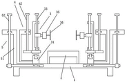
FIG. 1 is a schematic structural diagram of the present invention.
Fig. 2 is an enlarged schematic structural view of the floating cutting mechanism and the angle adjusting mechanism of the present invention.
Detailed Description
The present invention will be described in further detail with reference to the accompanying drawings.
As shown in fig. 1 and 2, a multiple regulation type wind power blade flash cutting device comprises a base 1, a processing table 2, a floating cutting mechanism 3, an angle regulating mechanism 4 and a transverse regulating mechanism 5; a processing table 2 is arranged in the middle of the upper end of the base 1; two sides of the upper end of the base 1 are respectively provided with a floating cutting mechanism 3; the floating cutting mechanism 3 comprises a positioning block 31, a connecting cylinder 32, a longitudinal driving screw 33, a floating block 34, a cutting motor 35 and a cutting blade 36; two sides of the upper end of the base 1 are respectively provided with a positioning block 31; the upper ends of the positioning blocks 31 are respectively provided with a connecting cylinder 32; the inner sides of the connecting columns 32 are respectively provided with a longitudinal sliding chute 321; a floating block 34 is respectively installed in the longitudinal sliding groove 321 in a sliding and clamping manner up and down; the floating block 34 is provided with a threaded hole; a longitudinal driving screw 33 is respectively connected in the longitudinal sliding groove 321 of the connecting column 32 in a penetrating way; the longitudinal driving screw 33 is rotatably clamped and connected in the longitudinal sliding groove 321 of the connecting cylinder 32, and the upper end of the longitudinal driving screw 33 extends to the upper part of the connecting cylinder 32; the longitudinal driving screw rod 33 is threaded on a threaded hole of the floating block 34; a cutting motor 35 is respectively arranged on the inner sides of the floating blocks 34; the inner sides of the cutting motors 35 are respectively provided with cutting blades 36 through rotating shafts; the lower end of the connecting cylinder 32 is rotatably clamped at the upper end of the positioning block 31; the angle adjusting mechanism 4 comprises a connecting bracket 41, an angle adjusting rod 42, an angle adjusting gear 43 and a rotating gear ring 44; the outer sides of the floating cutting mechanisms 3 are respectively provided with an angle adjusting mechanism 4; the outer sides of the positioning blocks 31 are respectively provided with a connecting bracket 41; the lower end of the connecting bracket 41 is fixed on the outer side of the positioning block 31, and the upper end of the connecting bracket 41 is respectively rotatably clamped with an angle adjusting rod 42; the lower end of the angle adjusting rod 42 is provided with an angle adjusting gear 43; the periphery of the lower end of the connecting column 32 is respectively provided with a rotating gear ring 44; the angle adjusting gear 43 is meshed with the rotating gear ring 44; the outer sides of the angle adjusting mechanisms 4 are respectively provided with a transverse adjusting mechanism 5; the transverse adjusting mechanism 5 comprises a positioning plate 51, a transverse adjusting rod 52, a transverse adjusting gear 53 and a transverse sliding toothed plate 54; two sides of the base 1 are respectively provided with a transverse clamping groove 19; a transverse sliding toothed plate 54 is respectively installed in the transverse clamping grooves 19 in a sliding clamping mode; the bottom of the positioning block 31 is connected to the upper side of the inner end of the transverse sliding toothed plate 54 of the transverse clamping groove 19 through an extension rod; a positioning plate 51 is respectively arranged above two sides of the base 1; a transverse adjusting rod 52 is rotatably clamped on the positioning plate 51; the lower ends of the transverse adjusting rods 52 are respectively provided with a transverse adjusting gear 53; the transverse adjusting gears 53 are respectively engaged with one side of the outer end of the transverse sliding toothed plate 54.
As shown in fig. 1 and 2, further, a clamping ring body is arranged on the outer side of the periphery of the angle adjusting rod 42; the upper end of the connecting bracket 41 is provided with a positioning rotating groove; the angle adjusting rod 42 is rotatably clamped in the positioning rotating groove at the upper end of the connecting bracket 41 through clamping ring bodies on the outer sides of the periphery. Further, a clamping rotating rod is arranged at the lower end of the connecting cylinder 32; the upper end of the positioning block 31 is provided with a clamping rotary groove; the connecting cylinder 32 is rotatably clamped on the clamping rotary groove at the upper end of the positioning block 31 through a clamping rotary rod at the lower end. Further, the lower end of the longitudinal driving screw 33 is provided with a rotary clamping tooth; the lower end of the longitudinal sliding groove 321 of the connecting column 32 is provided with a rotary clamping groove; the longitudinal driving screw 33 is rotatably clamped in the rotary clamping groove at the lower end of the longitudinal sliding groove 321 of the connecting cylinder 32 through the rotary clamping tooth at the lower end.
The invention is additionally provided with the transverse adjusting mechanism 5, the transverse adjusting gear 53 is driven to rotate by rotating the transverse adjusting rod 52, the transverse sliding toothed plate 54 is driven to slide in the transverse clamping groove 19 of the base 1 by the meshing action of the gears, and thus the positioning block 31 and the whole floating cutting mechanism 3 are driven to move transversely, thereby realizing the transverse position adjustment of cutting.
The adjustment of the cutting horizontal angle is realized, so that the cutting can be carried out according to the radian of the flash of the wind power blade, and the convenience of flash cutting is realized; according to the invention, the angle adjusting rod 42 is rotated on the connecting bracket 41 to drive the angle adjusting gear 43 to rotate, the angle adjusting gear 43 and the rotating gear ring 44 are driven to rotate through the meshed connecting structure of the angle adjusting gear 43 and the rotating gear ring 44, so that the connecting cylinder 32 is driven to rotate above the positioning block 31, the horizontal angle of the cutting blade 36 is adjusted, and the cutting convenience is realized.
The above description is only for the purpose of illustrating the preferred embodiments of the present invention and is not to be construed as limiting the invention, and any modifications, equivalents, improvements and the like that fall within the spirit and principle of the present invention are intended to be included therein.
Claims (4)
1. A multi-regulation type wind power blade flash cutting device is characterized by comprising a base, a processing table, a floating cutting mechanism, an angle regulating mechanism and a transverse regulating mechanism; a processing table is arranged in the middle of the upper end of the base; two sides of the upper end of the base are respectively provided with a floating cutting mechanism; the floating cutting mechanism comprises a positioning block, a connecting cylinder, a longitudinal driving screw, a floating block, a cutting motor and a cutting blade; two sides of the upper end of the base are respectively provided with a positioning block; the upper ends of the positioning blocks are respectively provided with a connecting cylinder; the inner sides of the connecting cylinders are respectively provided with a longitudinal sliding chute; a floating block is respectively installed in the longitudinal sliding groove in a vertically sliding and clamping manner; the floating block is provided with a threaded hole; a longitudinal driving screw rod is respectively connected in the longitudinal sliding groove of the connecting column body in a penetrating manner; the longitudinal driving screw rod is rotatably clamped and connected in the longitudinal sliding groove of the connecting cylinder in a penetrating manner, and the upper end of the longitudinal driving screw rod extends to the upper part of the connecting cylinder; the longitudinal driving screw is in threaded connection with the threaded hole of the floating block; the inner sides of the floating blocks are respectively provided with a cutting motor; cutting blades are respectively arranged on the inner sides of the cutting motors through rotating shafts; the lower end of the connecting cylinder is rotationally clamped at the upper end of the positioning block; the angle adjusting mechanism comprises a connecting bracket, an angle adjusting rod, an angle adjusting gear and a rotating gear ring; the outer sides of the floating cutting mechanisms are respectively provided with an angle adjusting mechanism; the outer sides of the positioning blocks are respectively provided with a connecting bracket; the lower end of the connecting bracket is fixed on the outer side of the positioning block, and the upper end of the connecting bracket is respectively provided with an angle adjusting rod in a rotating clamping manner; the lower end of the angle adjusting rod is provided with an angle adjusting gear; the periphery of the lower end of the connecting column body is respectively provided with a rotating gear ring; the angle adjusting gear is in meshed connection with the rotating gear ring; the outer sides of the angle adjusting mechanisms are respectively provided with a transverse adjusting mechanism; the transverse adjusting mechanism comprises a positioning plate, a transverse adjusting rod, a transverse adjusting gear and a transverse sliding toothed plate; two sides of the base are respectively provided with a transverse clamping groove; a transverse sliding toothed plate is respectively installed in the transverse clamping grooves in a sliding and clamping manner; the bottom of the positioning block is connected to the upper side of the inner end of the transverse sliding toothed plate of the transverse clamping groove through an extension rod; a positioning plate is respectively arranged above two sides of the base; the positioning plates are respectively provided with a transverse adjusting rod in a rotating and clamping way; the lower ends of the transverse adjusting rods are respectively provided with a transverse adjusting gear; the transverse adjusting gears are respectively connected to one side of the outer end of the transverse sliding toothed plate in an engaged manner.
2. The multi-adjustment type wind power blade flash cutting device according to claim 1, wherein clamping ring bodies are arranged on the outer sides of the peripheries of the angle adjusting rods; the upper end of the connecting bracket is provided with a positioning rotating groove; the angle adjusting rod is rotatably clamped in the positioning rotating groove at the upper end of the connecting support through the clamping ring bodies on the periphery of the angle adjusting rod.
3. The multi-adjustment type wind power blade flash cutting device according to claim 1, wherein a clamping rotating rod is arranged at the lower end of the connecting cylinder; the upper end of the positioning block is provided with a clamping rotary groove; the connecting cylinder body is rotationally clamped on the clamping rotating groove at the upper end of the positioning block through the clamping rotating rod at the lower end.
4. The multi-adjustment type wind power blade flashing cutting device according to claim 1, wherein the lower end of the longitudinal driving screw is provided with a rotary clamping tooth; the lower end of the longitudinal sliding groove of the connecting cylinder is provided with a rotary clamping groove; the longitudinal driving screw is rotationally clamped on the rotary clamping groove at the lower end of the longitudinal sliding groove of the connecting cylinder body through the rotary clamping teeth at the lower end.
Priority Applications (1)
| Application Number | Priority Date | Filing Date | Title |
|---|---|---|---|
| CN202110212284.0A CN112936684A (en) | 2021-02-25 | 2021-02-25 | Multi-regulation type wind power blade flash cutting device |
Applications Claiming Priority (1)
| Application Number | Priority Date | Filing Date | Title |
|---|---|---|---|
| CN202110212284.0A CN112936684A (en) | 2021-02-25 | 2021-02-25 | Multi-regulation type wind power blade flash cutting device |
Publications (1)
| Publication Number | Publication Date |
|---|---|
| CN112936684A true CN112936684A (en) | 2021-06-11 |
Family
ID=76246222
Family Applications (1)
| Application Number | Title | Priority Date | Filing Date |
|---|---|---|---|
| CN202110212284.0A Pending CN112936684A (en) | 2021-02-25 | 2021-02-25 | Multi-regulation type wind power blade flash cutting device |
Country Status (1)
| Country | Link |
|---|---|
| CN (1) | CN112936684A (en) |
Cited By (3)
| Publication number | Priority date | Publication date | Assignee | Title |
|---|---|---|---|---|
| CN113478542A (en) * | 2021-07-19 | 2021-10-08 | 东台市富安合成材料有限公司 | Abutting pressure adjusting type synthetic leather cutting device and cutting manufacturing process thereof |
| CN113815040A (en) * | 2021-09-13 | 2021-12-21 | 东台永胜盈华游艇有限公司 | Multi-angle adjusting type yacht shell cutting mechanism |
| CN114347151A (en) * | 2022-01-11 | 2022-04-15 | 领胜城科技(江苏)有限公司 | Filtering and deslagging type nanocrystalline cutting mechanism |
Citations (5)
| Publication number | Priority date | Publication date | Assignee | Title |
|---|---|---|---|---|
| CN110508878A (en) * | 2019-09-18 | 2019-11-29 | 河北炬亮科技有限公司 | A kind of automatic numerical-controlled gantry cutting machine |
| CN211415973U (en) * | 2019-11-26 | 2020-09-04 | 苏州羽美尚精密机械有限公司 | Ring class working of plastics burring instrument that adaptation degree is high |
| CN211941085U (en) * | 2020-03-23 | 2020-11-17 | 上海玻璃钢研究院东台有限公司 | Double-regulation type wind power blade flash cutting device |
| CN212288364U (en) * | 2020-04-23 | 2021-01-05 | 重庆彼欧英瑞杰汽车系统有限公司 | A plastic fuel tank trimming mechanism |
| CN112248322A (en) * | 2020-09-15 | 2021-01-22 | 江阴市科诚模具翻转系统有限公司 | Edge cutting method for main beam of wind power blade |
-
2021
- 2021-02-25 CN CN202110212284.0A patent/CN112936684A/en active Pending
Patent Citations (5)
| Publication number | Priority date | Publication date | Assignee | Title |
|---|---|---|---|---|
| CN110508878A (en) * | 2019-09-18 | 2019-11-29 | 河北炬亮科技有限公司 | A kind of automatic numerical-controlled gantry cutting machine |
| CN211415973U (en) * | 2019-11-26 | 2020-09-04 | 苏州羽美尚精密机械有限公司 | Ring class working of plastics burring instrument that adaptation degree is high |
| CN211941085U (en) * | 2020-03-23 | 2020-11-17 | 上海玻璃钢研究院东台有限公司 | Double-regulation type wind power blade flash cutting device |
| CN212288364U (en) * | 2020-04-23 | 2021-01-05 | 重庆彼欧英瑞杰汽车系统有限公司 | A plastic fuel tank trimming mechanism |
| CN112248322A (en) * | 2020-09-15 | 2021-01-22 | 江阴市科诚模具翻转系统有限公司 | Edge cutting method for main beam of wind power blade |
Cited By (4)
| Publication number | Priority date | Publication date | Assignee | Title |
|---|---|---|---|---|
| CN113478542A (en) * | 2021-07-19 | 2021-10-08 | 东台市富安合成材料有限公司 | Abutting pressure adjusting type synthetic leather cutting device and cutting manufacturing process thereof |
| CN113478542B (en) * | 2021-07-19 | 2022-07-22 | 东台市富安合成材料有限公司 | Abutting pressure adjusting type synthetic leather cutting device and cutting manufacturing process thereof |
| CN113815040A (en) * | 2021-09-13 | 2021-12-21 | 东台永胜盈华游艇有限公司 | Multi-angle adjusting type yacht shell cutting mechanism |
| CN114347151A (en) * | 2022-01-11 | 2022-04-15 | 领胜城科技(江苏)有限公司 | Filtering and deslagging type nanocrystalline cutting mechanism |
Similar Documents
| Publication | Publication Date | Title |
|---|---|---|
| CN100558494C (en) | Worm and screw processing device | |
| CN112936685A (en) | Angle modulation type wind-powered electricity generation blade overlap cutting device | |
| CN216966433U (en) | Full-automatic pipe cutting machine | |
| CN220971553U (en) | Processing clamping structure of circumference wave-shaped edge milling cutter | |
| CN119682081A (en) | A rotary water jet cutting device for discarded wind turbine blades | |
| CN116076325A (en) | A compound movement type natural rubber automatic tapping machine | |
| CN209021364U (en) | Tooth covers processing unit (plant) | |
| CN215316209U (en) | Plasma flame cutting machine is used in production of bull-dozer balance beam frame | |
| CN215618398U (en) | A cutting device for processing EPS decorative lines | |
| CN116422975A (en) | A saw blade gear grinding machine with adjustable saw disc diameter | |
| CN102029492A (en) | Three-cutting torch curve groove cutting device | |
| CN219881872U (en) | Aluminum alloy template positioning mechanism | |
| CN200988155Y (en) | Part grinding surface angle regulating mechanism for crystal surface grinder | |
| CN201179585Y (en) | Top circle cutting machine of helical cutter knife | |
| CN218080529U (en) | Part drilling mechanism of rotary type blade mould | |
| CN221136078U (en) | Photovoltaic board cutting device | |
| CN220717947U (en) | Plate cutting saw for cutting metal plate | |
| CN120985436B (en) | Diamond composite cutting tooth high-speed grinding repairing device | |
| CN209648918U (en) | A kind of plate shearing machine for wardrobe production | |
| CN201677113U (en) | Planar arc cutting device | |
| CN213259963U (en) | wood cutting machine for furniture | |
| CN222791256U (en) | Milling flutes fixing device convenient to machining | |
| CN220128254U (en) | Grooving device for metal pipe fittings | |
| CN216176095U (en) | Automatic feed pipe mill | |
| CN221603122U (en) | Cutting device for cable production |
Legal Events
| Date | Code | Title | Description |
|---|---|---|---|
| PB01 | Publication | ||
| PB01 | Publication | ||
| SE01 | Entry into force of request for substantive examination | ||
| SE01 | Entry into force of request for substantive examination | ||
| RJ01 | Rejection of invention patent application after publication |
Application publication date: 20210611 |
|
| RJ01 | Rejection of invention patent application after publication |