CN112933734A - Zero-emission waste treatment system and method - Google Patents
Zero-emission waste treatment system and method Download PDFInfo
- Publication number
- CN112933734A CN112933734A CN202110246173.1A CN202110246173A CN112933734A CN 112933734 A CN112933734 A CN 112933734A CN 202110246173 A CN202110246173 A CN 202110246173A CN 112933734 A CN112933734 A CN 112933734A
- Authority
- CN
- China
- Prior art keywords
- sewage
- tank
- wheel
- pipeline
- sand
- Prior art date
- Legal status (The legal status is an assumption and is not a legal conclusion. Google has not performed a legal analysis and makes no representation as to the accuracy of the status listed.)
- Granted
Links
- 239000002699 waste material Substances 0.000 title claims abstract description 72
- 238000000034 method Methods 0.000 title claims description 9
- 239000010865 sewage Substances 0.000 claims abstract description 194
- XLYOFNOQVPJJNP-UHFFFAOYSA-N water Substances O XLYOFNOQVPJJNP-UHFFFAOYSA-N 0.000 claims abstract description 74
- 239000004575 stone Substances 0.000 claims abstract description 54
- 238000003756 stirring Methods 0.000 claims abstract description 42
- 238000011010 flushing procedure Methods 0.000 claims abstract description 33
- 238000011084 recovery Methods 0.000 claims abstract description 26
- 239000000463 material Substances 0.000 claims abstract description 22
- 239000007921 spray Substances 0.000 claims abstract description 13
- 238000004140 cleaning Methods 0.000 claims abstract description 11
- 101100041681 Takifugu rubripes sand gene Proteins 0.000 claims description 58
- 239000004576 sand Substances 0.000 claims description 58
- 238000007599 discharging Methods 0.000 claims description 20
- 239000007788 liquid Substances 0.000 claims description 16
- 230000000903 blocking effect Effects 0.000 claims description 9
- 238000001914 filtration Methods 0.000 claims description 9
- 238000005406 washing Methods 0.000 claims description 9
- 230000005540 biological transmission Effects 0.000 claims description 6
- 238000010790 dilution Methods 0.000 claims description 4
- 239000012895 dilution Substances 0.000 claims description 4
- 230000008878 coupling Effects 0.000 claims description 3
- 238000010168 coupling process Methods 0.000 claims description 3
- 238000005859 coupling reaction Methods 0.000 claims description 3
- 230000002093 peripheral effect Effects 0.000 claims description 3
- 230000008569 process Effects 0.000 claims description 2
- 238000001514 detection method Methods 0.000 description 3
- 238000010586 diagram Methods 0.000 description 3
- 239000002969 artificial stone Substances 0.000 description 2
- 238000005086 pumping Methods 0.000 description 2
- 239000002002 slurry Substances 0.000 description 2
- 238000005507 spraying Methods 0.000 description 2
- 230000032258 transport Effects 0.000 description 2
- 239000000654 additive Substances 0.000 description 1
- 230000000996 additive effect Effects 0.000 description 1
- 230000009286 beneficial effect Effects 0.000 description 1
- 238000010276 construction Methods 0.000 description 1
- 230000007547 defect Effects 0.000 description 1
- 238000012423 maintenance Methods 0.000 description 1
- 238000004519 manufacturing process Methods 0.000 description 1
- 238000012986 modification Methods 0.000 description 1
- 230000004048 modification Effects 0.000 description 1
- 238000004080 punching Methods 0.000 description 1
- 239000000243 solution Substances 0.000 description 1
- 239000002351 wastewater Substances 0.000 description 1
Images








Classifications
-
- B—PERFORMING OPERATIONS; TRANSPORTING
- B01—PHYSICAL OR CHEMICAL PROCESSES OR APPARATUS IN GENERAL
- B01D—SEPARATION
- B01D36/00—Filter circuits or combinations of filters with other separating devices
- B01D36/04—Combinations of filters with settling tanks
- B01D36/045—Combination of filters with centrifugal separation devices
Landscapes
- Chemical & Material Sciences (AREA)
- Chemical Kinetics & Catalysis (AREA)
- Filtration Of Liquid (AREA)
Abstract
The invention relates to a zero-emission waste treatment system which comprises a material flushing groove, a wheel type sand-stone separator, a cyclone, a sewage tank, a clean water tank and a sewage stirring tank, wherein a spray pipe is arranged above the material flushing groove, the wheel type sand-stone separator and the sewage tank are sequentially communicated to form a primary recovery system, the sewage tank, the cyclone and the sewage stirring tank are sequentially communicated in a closed loop manner to form a secondary recovery system, the sewage stirring tank and the clean water tank are connected to the spray pipe through pipelines to form a flushing system, the clean water tank is connected to the sewage stirring tank through pipelines to form a concentration adjusting system, and a cleaning pipeline communicated to the wheel type sand-stone separator is further arranged on. The zero-emission waste treatment system is simple in structure and high in working efficiency.
Description
Technical Field
The invention relates to the technical field of construction waste treatment, in particular to a zero-emission waste treatment system and a zero-emission waste treatment method.
Background
The concrete is the most important civil engineering material in building production, and is an artificial stone material prepared by a cementing material, granular aggregate, water, an additive and an admixture which are added if necessary according to a certain proportion, and the artificial stone material is formed by uniformly stirring, compacting, curing and hardening. The existing waste recovery system can separate and recover sand, stone and sewage in waste, but the structure is complex, the waste recovery needs to carry out a plurality of steps, and the working efficiency is low.
Disclosure of Invention
In order to overcome the technical defects in the prior art, the invention provides a zero-emission waste treatment system which is simple in structure and high in working efficiency.
The technical solution adopted by the invention is as follows: zero release waste material processing system, including towards silo, wheeled sand and stone separator, swirler, effluent water sump, clean water basin and sewage agitator tank, towards the silo top and be equipped with the shower, towards silo, wheeled sand and stone separator and effluent water sump intercommunication in order and constitute a recovery system, effluent water sump, swirler and sewage agitator tank closed loop intercommunication in order constitute secondary recovery system, sewage agitator tank and clean water basin pass through pipe connection to shower and constitute rinse-system, the clean water basin passes through pipe connection to the sewage agitator tank and constitutes concentration control system, still is equipped with the cleaning tube who communicates to wheeled sand and stone separator on the clean water basin.
Preferably, the wheeled sand-stone separator comprises a rack, a rotary screen arranged in front of the rack and a wheel bucket arranged behind the rack, the rotary screen and the wheel bucket can be rotatably mounted on the rack, a roller driving motor and a wheel bucket driving motor which respectively drive the rotary screen and the wheel bucket to rotate are arranged on the rack, a waste material inlet is formed in the right end of the rotary screen, a stone block outlet is formed in the rack below the left side of the rotary screen, a sewage tank is arranged below the rotary screen and the wheel bucket, an overflow groove is formed in the sewage tank, a liquid drainage channel communicated with the overflow groove is formed in the bottom of the sewage tank, and a fine sand outlet is formed in the rear end of the sewage tank.
Preferably, the bottom of bilge pit is equipped with the drain, install waste fitting discharging on the drain, waste fitting discharging mounting bracket, shutoff stopper and electric putter, the one end rigid coupling of mounting bracket is in the drain outer peripheral edges, the shutoff stopper can with the sealed cooperation of drain, electric putter installs on the mounting bracket, the end at electric putter is installed to the shutoff stopper, and the shutoff stopper is at electric putter's drive in the drain or leave the drain.
Preferably, the trommel screen comprises a filter cylinder and helical blades arranged in the filter cylinder, a plurality of filter holes are formed in the filter cylinder, a rotating shaft is arranged on the central axis of the filter cylinder and is installed in the filter cylinder through a support frame, and the left end of the rotating shaft is in transmission connection with a filter cylinder driving motor.
Preferably, the wheel fill includes the cylinder, a support piece is installed respectively to the axial both sides of cylinder, and one of them support piece is connected with wheel fill driving motor transmission, evenly be equipped with a plurality of sand washing fill along circumference on the wheel fill outer wall.
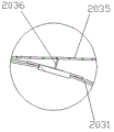
Preferably, the outer wall of the roller is provided with two annular wheel plates, an annular baffle plate is further arranged between the two wheel plates, a plurality of filter plates are obliquely arranged between each wheel plate and the annular baffle plate respectively, filter holes are formed in the filter plates and the roller, the filter plates, the annular baffle plates and the wheel plates surround a plurality of sand washing hoppers on the outer wall of the roller, a material blocking bottom plate is arranged at the joint of the roller and each filter plate, and four side end faces of the material blocking bottom plate are connected with the filter plates, the roller, the wheel plates and the annular baffle plate respectively.
Preferably, the effluent water sump is accepted in wheeled sand and stone separator's flowing back way below, the wheel fill top at wheeled sand and stone separator is installed to the swirler, be equipped with the sewage pump in the effluent water sump, the sewage pump is connected to the feed inlet of swirler through taking out the thick liquid pipeline, and the liquid outlet pipeline of swirler communicates to the sewage agitator tank, the sewage agitator tank is connected to the effluent water sump through the blowdown pipeline, and the dewatering screen has been accepted to swirler below discharge gate, the discharge gate of dewatering screen is established in wheeled sand and stone separator's fine sand export top.
Preferably, the clean water tank is communicated with the spray pipe through a first clean water pipeline, the right end of the flushing groove is communicated with a waste inlet pipeline of the drum screen, the sewage stirring tank is communicated with the left end of the flushing groove through a sewage pipeline, a flushing water pump communicated with the sewage pipeline is arranged in the sewage stirring tank, a branch pipeline is arranged on the sewage pipeline, the tail end of the branch pipeline is communicated with the spray pipe, an overflow pipeline is further arranged on the sewage stirring tank, and the overflow pipeline is communicated with the left end of the flushing groove.
Preferably, the clean water tank is connected to the sewage agitator tank through a second clean water pipeline, and a clean water pump communicated with the clean water pipeline is arranged in the clean water tank.
The invention also provides a zero-emission waste treatment method, which adopts the zero-emission waste treatment system and comprises the following steps:
s1, starting a spray pipe to discharge clear water or sewage into the tank car to clean the tank car, and discharging waste materials into a material flushing groove by the tank car after cleaning;
s2, flushing the waste into a feed inlet of the wheel type sand-stone separator by using the sewage in the sewage stirring tank;
s3, starting the wheel type sand-stone separator, respectively discharging stones and fine sand in the waste, and discharging sewage into a sewage pool;
s4, conveying the sewage in the sewage tank to a cyclone for secondary filtration, discharging fine sand from the lower part of the cyclone, discharging the sewage after secondary filtration from the upper part of the cyclone, and conveying the sewage to a sewage stirring tank;
and S5, when the sewage concentration in the sewage stirring tank does not reach the standard, injecting clear water into the sewage stirring tank for dilution until the sewage concentration reaches the standard, stopping injecting the clear water, when the liquid level in the sewage stirring tank reaches the highest value and the sewage concentration does not reach the standard, discharging the sewage back to the sewage pool, and returning to S4.
The invention has the beneficial effects that:
(1) the zero-emission waste treatment system can separate and recover sand, stone and sewage in the waste, and can adjust the concentration of the separated sewage and filter the separated sewage for multiple times, so that the sewage reaches the recovery standard, and zero emission of waste treatment is realized;
(2) the zero-discharge waste treatment system comprises a flushing groove, a wheel type sand-stone separator, a sewage pool, a cyclone, a clean water pool and a sewage stirring tank, has simple structure and complete functions, all the components are connected into an organic whole through pipelines, the flushing groove, the wheel type sand-stone separator and the sewage pool are sequentially communicated to form a primary recovery system, the sewage pool, the cyclone and the sewage stirring tank are sequentially communicated in a closed loop manner to form a secondary recovery system, the primary recovery system filters stones and part of fine sand, sewage passing through the primary recovery system is always dynamically circulated in the secondary recovery system, simultaneously, the sewage concentration in the sewage stirring tank is adjusted in real time through the clean water pool, a user can take qualified sewage from the sewage stirring tank in real time, the sewage is continuously filtered in the dynamic circulation process, the recovery rate of waste is greatly improved, and the sewage also participates in the flushing operation of the flushing system, the use amount of clear water is reduced;
(3) the secondary recovery system of the zero-emission waste treatment system is formed by sequentially communicating a wheel type sand-stone separator, a sewage pool, a cyclone and a sewage stirring tank in a closed loop manner, sewage in the secondary recovery system is always in dynamic circulation, and after the fine sand in the waste is recovered for the first time, the rest fine sand which is not recovered is continuously recovered in the secondary recovery system, so that the recovery rate of the fine sand and the overall working efficiency of the system are greatly improved;
(4) the zero-emission waste treatment system adopts the wheel type sand-stone separator as a core filtering device, the filtering part of the zero-emission waste treatment system comprises a drum screen and a wheel hopper, the drum screen recovers stones, the wheel hopper recovers fine sand for the first time and the second time, and the drum screen and the wheel hopper are respectively merged into the recovery system to participate in waste recovery, have compact structure and can be matched with all parts of the system.
Drawings
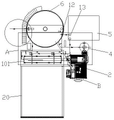
FIG. 1 is a schematic diagram of the configuration of a zero emission waste treatment system according to the present invention.
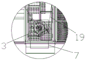
Fig. 2 is a partially enlarged view of a portion a in fig. 1.
Fig. 3 is a partially enlarged view of B in fig. 1.
Figure 4 is a side view of the zero emission waste treatment system of the present invention.
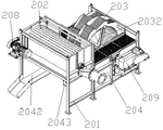
FIG. 5 is a first schematic structural view of the wheel-type sand separator of the present invention.
FIG. 6 is a second schematic structural view of the wheel-type sand separator of the present invention.
Fig. 7 is a schematic structural view of the trommel of the present invention.
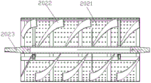
Fig. 8 is a cross-sectional view of a trommel of the present invention.
Fig. 9 is a schematic structural view of the wheel bucket of the present invention.
Fig. 10 is a cross-sectional view of the wheel bucket of the present invention.
Fig. 11 is a partial enlarged view at C in fig. 10.
Fig. 12 is a first structural schematic diagram of the sewage draining device of the present invention.
Fig. 13 is a second structural schematic diagram of the sewage draining device of the present invention.
FIG. 14 is a schematic view of the assembly of an isopipe.
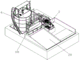
Figure 15 is a practical assembly drawing of the zero emission waste treatment system of the invention.
Description of reference numerals: 101. a material punching groove; 102. a shower pipe; 2. a wheel type sand-stone separator; 201. a frame; 202. a drum screen; 2021. a filter cartridge; 2022. a helical blade; 2023. a rotating shaft; 2024. a support frame; 203. a wheel hopper; 2031. a drum; 2032. a support member; 2033. a wheel plate; 2034. an annular baffle; 2035. a filter plate; 2036. a material blocking bottom plate; 204. a sewage tank; 2041. an overflow trough; 2042. a drainage channel; 2043. a sewage draining device; 20431. a mounting frame; 20432. an electric push rod; 20433. blocking; 205. a grid pedal; 206. a fine sand outlet; 207. a stone outlet; 208. a drum driving motor; 209. a wheel bucket driving motor; 3. a swirler; 4. a sewage tank; 5. a clean water tank; 6. a sewage stirring tank; 601. a stirring device; 602. a concentration detection device; 7. dewatering screen; 801. a first clear water line; 802. a second clear water pipeline; 9. a sewage pipeline; 901. a branch line; 10. an overflow line; 11. a sewage draining pipeline; 12. a water pump is flushed; 13. a clean water pump; 14. a sewage pump; 15. a control cabinet; 16. an air compressor; 18. cleaning a pipeline; 19. a slurry pumping pipeline; 20. a reverse slope.
Detailed Description
The invention will be further described with reference to the accompanying drawings in which:
as shown in fig. 1 to 15, the present embodiment provides a zero-emission waste treatment system, which includes a material flushing tank 101, a wheel type sand-stone separator 2, a cyclone 3, a sewage tank 4, a clean water tank 5 and a sewage stirring tank 6, wherein a spraying pipe 102 is arranged above the material flushing tank 101, the wheel type sand-stone separator 2 and the sewage tank 4 are sequentially communicated to form a primary recovery system, the sewage tank 4, the cyclone 3 and the sewage stirring tank 6 are sequentially communicated in a closed loop to form a secondary recovery system, the sewage stirring tank 6 and the clean water tank 5 are connected to the spraying pipe 102 through a pipeline to form a flushing system, the clean water tank 5 is connected to the sewage stirring tank 6 through a pipeline to form a concentration regulation system, and the clean water tank 5 is further provided with a cleaning pipeline 18 communicated. The zero-emission waste treatment system of the embodiment has the advantages of simple structure, complete functions and high working efficiency.
In this embodiment, the wheel type sand-stone separator 2 includes a frame 201, a trommel 202 disposed in front of the frame 201, and a wheel bucket 203 disposed in back of the frame 201, the trommel 202 and the wheel bucket 203 are both rotatably mounted on the frame 201, the frame 201 is provided with a drum driving motor 208 and a wheel bucket driving motor 209 for respectively driving the trommel 202 and the wheel bucket 203 to rotate, the right end of the trommel 202 is provided with a waste material inlet, the frame 201 on the lower left of the trommel 202 is provided with a stone outlet 207, a sewage tank 204 is disposed below the trommel 202 and the wheel bucket 203, the sewage tank 204 is provided with an overflow chute 2041 therein, the bottom of the sewage tank 204 is provided with a liquid discharge channel 2042 communicated with the overflow chute 2041, the back end of the sewage tank 204 is provided with a fine sand outlet 206, waste material in the flushing tank 101 enters the trommel 202 from the waste material inlet, fine sand and waste water in the waste material are filtered, the stones are transported to the stone outlet 207, and the wheel hopper 203 is rotated by the wheel hopper driving motor 209 to filter out and transport the fine sand of the sewage tank 204 to the fine sand outlet 206. Preferably, the trommel 202 comprises a filter cylinder 2021 and a helical blade 2022 arranged in the filter cylinder 2021, the filter cylinder 2021 is provided with a plurality of filter holes, a rotating shaft 2023 is arranged on the central axis of the filter cylinder 2021, the rotating shaft 2023 is installed in the filter cylinder 2021 through a support frame 2024, the left end of the rotating shaft 2023 is in transmission connection with a drum driving motor 208, and when the trommel 202 rotates, the helical blade 2022 pushes the stones to the stone outlet 207.
In this embodiment, the bottom of sewage tank 204 is equipped with the drain, install waste fitting 2043 on the drain, waste fitting 2043 includes mounting bracket 20431, shutoff stopper 20433 and electric putter 20432, the one end rigid coupling of mounting bracket 20431 is in the drain outer peripheral edges, shutoff stopper 20433 can with the sealed cooperation of drain, electric putter 20432 installs on mounting bracket 20431, the end at electric putter 20432 is installed to the shutoff stopper 20433, the shutoff stopper 20433 can be at the drive of electric putter 20432 in the shutoff in the drain or leave the drain, can be with sewage tank 204 evacuation, convenient maintenance and cleanness through opening the drain.
In this embodiment, the wheel hopper 203 includes a roller 2031, two axial sides of the roller 2031 are respectively provided with a supporting member 2032, one of the supporting members 2032 is in transmission connection with the wheel hopper driving motor 209, the outer wall of the wheel hopper 203 is uniformly provided with a plurality of sand washing hoppers along the circumferential direction, and the sand washing hoppers scoop up the fine sand in the sewage tank 204 and convey the fine sand to the fine sand outlet 206. Preferably, the outer wall of the drum 2031 is provided with two annular wheel plates 2033, an annular baffle 2034 is further arranged between the two wheel plates 2033, a plurality of filter plates 2035 are obliquely arranged between each wheel plate 2033 and the annular baffle 2034 respectively, filter holes are formed in the filter plates 2035 and the drum 2031, the filter plates 2035, the annular baffle 2034 and the wheel plates 2033 surround the outer wall of the drum 2031 to form a plurality of sand washing hoppers, a material blocking bottom plate 2036 is arranged at the joint of the drum 2031 and each filter plate 2035, four side end faces of the material blocking bottom plate 2036 are respectively connected with the filter plates 2035, the drum 2031, the wheel plates 2033 and the annular baffle 2034, the material blocking bottom plate 2036 can prevent material from being blocked, and the wheel hopper 203 can pour out all fine sand in the sand washing hoppers as much as possible. The periphery of the drum screen 202 and the wheel hopper 203 is respectively coated with a box body, the top of each box body is provided with a grid pedal 205, so that the internal situation of the wheel type sand-stone separator can be conveniently observed, the clean water tank 5 is also provided with a cleaning pipeline 18 communicated to the two box bodies, so that the interior of the wheel type sand-stone separator 2 can be conveniently cleaned, preferably, the cleaning pipeline 18 is led out from a first clean water pipeline 801, and a valve is arranged on the cleaning pipeline 18.
In this embodiment, the clean water tank 5 is communicated with the spray pipe 102 through a first clean water pipeline 801, a valve is arranged on the first clean water pipeline 801, the right end of the flushing tank 101 is communicated with a waste inlet pipeline of the drum screen 202, the sewage stirring tank 6 is communicated with the left end of the flushing tank 101 through a sewage pipeline 9, a flushing water pump 12 communicated with the sewage pipeline 9 is arranged in the sewage stirring tank 6, a branch pipeline 901 is arranged on the sewage pipeline 9, the tail end of the branch pipeline 901 is communicated with the spray pipe 102, valves are arranged on the sewage pipeline 9 and the branch pipeline 901 thereof, an overflow pipeline 10 is further arranged on the sewage stirring tank 6, the overflow pipeline 10 is communicated with the left end of the flushing tank 101, after a tank car loaded with waste is driven to the slope 20, the spray pipe 102 sprays water to the interior of the tank car to facilitate the tank car to discharge the waste into the flushing tank 101, and then the flushing water pump 12 is started to flush the waste in the flushing tank 101 into the wheel type sand-stone separator 2, the overflow pipeline 10 ensures that the liquid level in the sewage stirring tank 6 cannot exceed the standard to cause sewage leakage.
In this embodiment, clean water basin 5 is connected to sewage agitator tank 6 through second clear water pipeline 802, be equipped with the clean water pump 13 with second clear water pipeline 802 intercommunication in the clean water basin 5, be equipped with agitating unit 601 and concentration detection device 602 in the sewage agitator tank 6, when concentration detection device 602 detects that the concentration of sewage does not reach standard in the sewage agitator tank 6, clean water pump 13 starts and pours into sewage agitator tank 6 with the clear water into, so dilute until the concentration is up to standard to sewage, and agitating unit 601 guarantees that sewage concentration is even in the sewage agitator tank 6.
In this embodiment, the sewage tank 4 is received below a liquid drainage 2042 of the wheel type sand-stone separator 2, the cyclone 3 is installed above a wheel hopper 203 of the wheel type sand-stone separator 2, a sewage pump 14 is arranged in the sewage tank 4, the sewage pump 14 is connected to a feed inlet of the cyclone 3 through a slurry pumping pipeline 19, a liquid outlet pipeline of the cyclone 3 is communicated to a sewage agitator tank 6, the sewage agitator tank 6 is connected to the sewage tank 4 through a sewage discharge pipeline 11, a valve is arranged on the sewage discharge pipeline 11, a discharge outlet of the cyclone 3 is received by a dewatering screen 7, a discharge outlet of the dewatering screen 7 is arranged above a fine sand outlet 206 of the wheel type sand-stone separator 2, when the height of the sewage liquid level in the sewage tank 204 is higher than the height of a notch of the overflow groove 2041, the sewage is discharged into the sewage tank 4 through the liquid drainage 2042, at this time, the concentration of the fine sand in the sewage tank 4 is higher, cyclone 3 functions and separates sewage, sewage is discharged by the liquid outlet of cyclone 3 top and is carried to sewage agitator tank 6, the fine sand is discharged and reachs dewatering screen 7 by the discharge gate of cyclone 3 below, dewatering screen 7 dewaters the fine sand and discharges, sewage falls back in sewage tank 204 again, when sewage concentration is too high unable dilution in sewage agitator tank 6, sewage agitator tank 6 accessible sewage pipes 11 transports sewage back to effluent water sump 4 and carries out the loop filter again, so, sewage in the system is in dynamic circulation always, the fine sand that is not retrieved will be continuously retrieved in secondary recovery system, improve the rate of recovery of fine sand and the holistic work efficiency of system greatly.
The working method of the zero-emission waste treatment system of the embodiment is as follows:
s1, when the tank car reaches the reversing slope 20, the spray pipe 102 is started to discharge clean water or sewage into the tank car to clean the tank car, and after the cleaning is finished, the tank car discharges waste into the material flushing groove 101;
s2, discharging the sewage in the sewage stirring tank 6 into a material flushing groove 101, and flushing the waste material into a feed inlet of the wheel type sand-stone separator 2 by using the sewage in the sewage stirring tank 6;
s3, the wheel type sand-stone separator 2 is started, stones in the waste are discharged from the stone outlet 207, fine sand is discharged from the fine sand outlet 206, and sewage is discharged into the sewage pool 4;
s4, conveying the sewage in the sewage tank 4 to the cyclone 3 for secondary filtration, discharging fine sand from the lower part of the cyclone 3, discharging the sewage after secondary filtration from the upper part of the cyclone 3 and conveying the sewage to the sewage stirring tank 6;
and S5, when the sewage concentration in the sewage stirring tank 6 does not reach the standard, injecting clear water into the sewage stirring tank 6 for dilution until the sewage concentration reaches the standard, stopping injecting the clear water, when the liquid level in the sewage stirring tank 6 reaches the highest value and the sewage concentration does not reach the standard, discharging the sewage back to the sewage pool 4, and returning to S4.
The zero release waste treatment system of this embodiment can be to the sand in the waste material, stone and sewage separate and retrieve, can carry out concentration control and filtration many times to the sewage that separates, make sewage reach the standard that can retrieve, waste treatment's zero release has been realized, and the simple structure of system, sewage carries out dynamic circulation in the system, sewage constantly filters at the dynamic circulation in-process, improve the rate of recovery and the holistic work efficiency of system of fine sand greatly, preferentially, the zero release waste treatment of this embodiment provides still including the air compressor machine 16 that provides power for each valve and control cabinet 15 of control entire system operation.
While there have been shown and described what are at present considered the fundamental principles and essential features of the invention and its advantages, it will be understood by those skilled in the art that the invention is not limited by the embodiments described above, which are merely illustrative of the principles of the invention, but that various changes and modifications may be made therein without departing from the spirit and scope of the invention as defined by the appended claims and their equivalents.
Claims (10)
1. Zero release waste material processing system, its characterized in that: including dashing silo, wheeled sand and stone separator, swirler, effluent water sump, clean water basin and sewage agitator tank, it is equipped with the shower to dash the silo top, dash silo, wheeled sand and stone separator and effluent water sump intercommunication in order and constitute a recovery system, effluent water sump, swirler and sewage agitator tank communicate closed loop in order and constitute secondary recovery system, sewage agitator tank and clean water basin pass through pipe connection to shower and constitute rinse system, the clean water basin passes through pipe connection to the sewage agitator tank and constitutes concentration control system, still is equipped with the cleaning tube who communicates to wheeled sand and stone separator on the clean water basin.
2. The zero emission waste treatment system of claim 1, wherein: the wheel type sand-stone separator comprises a rack, a rotary screen arranged in front of the rack and a wheel bucket arranged behind the rack, wherein the rotary screen and the wheel bucket can be rotatably arranged on the rack, a roller driving motor and a wheel bucket driving motor which respectively drive the rotary screen and the wheel bucket to rotate are arranged on the rack, a waste material inlet is arranged at the right end of the rotary screen, a stone block outlet is arranged on the rack below the left side of the rotary screen, a sewage tank is arranged below the rotary screen and the wheel bucket, an overflow groove is arranged in the sewage tank, a liquid drainage channel communicated with the overflow groove is arranged at the bottom of the sewage tank, and a fine sand outlet is arranged at the rear end of.
3. The zero emission waste treatment system of claim 2, characterized in that: the bottom of bilge pit is equipped with the drain, install waste fitting discharging on the drain, waste fitting discharging mounting bracket, shutoff stopper and electric putter, the one end rigid coupling of mounting bracket is in the drain outer peripheral edges, the shutoff stopper can be with the sealed cooperation of drain, electric putter installs on the mounting bracket, the end at electric putter is installed to the shutoff stopper, and the shutoff stopper is at electric putter's drive in the drain or leave the drain.
4. The zero emission waste treatment system of claim 2, characterized in that: the drum screen comprises a filter cylinder and spiral blades arranged in the filter cylinder, a plurality of filter holes are formed in the filter cylinder, a rotating shaft is arranged on the central axis of the filter cylinder and is installed in the filter cylinder through a support frame, and the left end of the rotating shaft is in transmission connection with a filter cylinder driving motor.
5. The zero emission waste treatment system of claim 2, characterized in that: the wheel fill includes the cylinder, a support piece is installed respectively to the axial both sides of cylinder, and one of them support piece is connected with wheel fill driving motor transmission, evenly be equipped with a plurality of sand washing fill along circumference on the wheel fill outer wall.
6. The zero emission waste treatment system of claim 5, wherein: the novel sand washing machine is characterized in that two annular wheel plates are arranged on the outer wall of the roller, an annular baffle plate is further arranged between the two wheel plates, a plurality of filter plates are obliquely arranged between each wheel plate and the annular baffle plate respectively, filter holes are formed in the filter plates and the roller, the filter plates, the annular baffle plates and the wheel plates surround a plurality of sand washing hoppers on the outer wall of the roller, a material blocking bottom plate is arranged at the joint of the roller and each filter plate, and four side end faces of the material blocking bottom plate are connected with the filter plates, the roller, the wheel plates and the annular baffle plate respectively.
7. The zero emission waste treatment system of claim 2, characterized in that: the sewage pond is accepted in wheeled sand and stone separator's flowing back way below, the wheel fill top at wheeled sand and stone separator is installed to the swirler, be equipped with the sewage pump in the sewage pond, the sewage pump is connected to the feed inlet of swirler through taking out the thick liquid pipe connection, and the liquid outlet pipeline of swirler communicates to the sewage agitator tank, the sewage agitator tank is connected to the sewage pond through blowdown pipeline, and dewatering screen has been accepted to swirler below discharge gate, dewatering screen's discharge gate is established in wheeled sand and stone separator's fine sand export top.
8. The zero emission waste treatment system of claim 2, characterized in that: the clean water tank is communicated with the spray pipe through a first clean water pipeline, the right end of the flushing groove is communicated with a waste inlet pipeline of the drum screen, the sewage stirring tank is communicated with the left end of the flushing groove through a sewage pipeline, a flushing water pump communicated with the sewage pipeline is arranged in the sewage stirring tank, a branch pipeline is arranged on the sewage pipeline, the tail end of the branch pipeline is communicated with the spray pipe, an overflow pipeline is further arranged on the sewage stirring tank, and the overflow pipeline is communicated with the left end of the flushing groove.
9. The zero emission waste treatment system of claim 2, characterized in that: the clean water basin is connected to the sewage agitator tank through a second clean water pipeline, a clean water pump communicated with the clean water pipeline is arranged in the clean water basin.
10. A zero emission waste treatment process using the zero emission waste treatment system of claim 1, characterized in that: the method comprises the following steps:
s1, starting a spray pipe to discharge clear water or sewage into the tank car to clean the tank car, and discharging waste materials into a material flushing groove by the tank car after cleaning;
s2, flushing the waste into a feed inlet of the wheel type sand-stone separator by using the sewage in the sewage stirring tank;
s3, starting the wheel type sand-stone separator, respectively discharging stones and fine sand in the waste, and discharging sewage into a sewage pool;
s4, conveying the sewage in the sewage tank to a cyclone for secondary filtration, discharging fine sand from the lower part of the cyclone, discharging the sewage after secondary filtration from the upper part of the cyclone, and conveying the sewage to a sewage stirring tank;
and S5, when the sewage concentration in the sewage stirring tank does not reach the standard, injecting clear water into the sewage stirring tank for dilution until the sewage concentration reaches the standard, stopping injecting the clear water, when the liquid level in the sewage stirring tank reaches the highest value and the sewage concentration does not reach the standard, discharging the sewage back to the sewage pool, and returning to S4.
Priority Applications (1)
| Application Number | Priority Date | Filing Date | Title |
|---|---|---|---|
| CN202110246173.1A CN112933734B (en) | 2021-03-05 | 2021-03-05 | Zero-emission waste treatment system and method |
Applications Claiming Priority (1)
| Application Number | Priority Date | Filing Date | Title |
|---|---|---|---|
| CN202110246173.1A CN112933734B (en) | 2021-03-05 | 2021-03-05 | Zero-emission waste treatment system and method |
Publications (2)
| Publication Number | Publication Date |
|---|---|
| CN112933734A true CN112933734A (en) | 2021-06-11 |
| CN112933734B CN112933734B (en) | 2022-07-01 |
Family
ID=76247909
Family Applications (1)
| Application Number | Title | Priority Date | Filing Date |
|---|---|---|---|
| CN202110246173.1A Active CN112933734B (en) | 2021-03-05 | 2021-03-05 | Zero-emission waste treatment system and method |
Country Status (1)
| Country | Link |
|---|---|
| CN (1) | CN112933734B (en) |
Citations (19)
| Publication number | Priority date | Publication date | Assignee | Title |
|---|---|---|---|---|
| GB903353A (en) * | 1960-02-12 | 1962-08-15 | Stamicarbon | Wet-screening apparatus |
| CN204892106U (en) * | 2015-08-18 | 2015-12-23 | 张辉 | Novel sand washer |
| CN205361117U (en) * | 2015-12-11 | 2016-07-06 | 江苏云阳集团药业有限公司 | Integration compounding device |
| KR101727152B1 (en) * | 2017-01-26 | 2017-04-14 | 전국찬 | Rinsing Machine for Making Molding Sand |
| CN206567083U (en) * | 2017-02-16 | 2017-10-20 | 赵山峰 | Highly effective coagulation soil paste retracting device |
| CN107470011A (en) * | 2017-09-23 | 2017-12-15 | 王伟华 | A kind of concrete gravel separates and recovers equipment |
| CN107585838A (en) * | 2017-09-14 | 2018-01-16 | 苏州天微至胜运动控制技术有限公司 | A kind of sandstone separates Disposal of Sewages |
| CN208131244U (en) * | 2018-01-12 | 2018-11-23 | 郑州三和水工机械有限公司 | A kind of concrete washing recovery system |
| CN109013044A (en) * | 2018-07-30 | 2018-12-18 | 佛山市缘懿科技有限公司 | A kind of sand washer of sandstone easy to clean |
| CN109127113A (en) * | 2018-09-19 | 2019-01-04 | 福建南方路面机械有限公司 | Wet concrete recovering system, recovery method and management-control method based on Internet of Things |
| CN109160626A (en) * | 2018-11-13 | 2019-01-08 | 青岛恩普环保设备有限公司 | Sewage treatment system with zero discharge |
| CN208800262U (en) * | 2018-06-05 | 2019-04-30 | 洛阳隆中重工机械有限公司 | A kind of roller sieves and washes all-in-one machine |
| CN209065447U (en) * | 2018-10-17 | 2019-07-05 | 青岛恩普环保设备有限公司 | Concentration of wastewater regulating device |
| CN209113612U (en) * | 2018-11-13 | 2019-07-16 | 青岛恩普环保设备有限公司 | Sewage treatment system with zero discharge |
| CN209438953U (en) * | 2018-12-08 | 2019-09-27 | 绍兴兴越干粉砂浆制造有限公司 | A kind of sand grains screening plant |
| CN110354987A (en) * | 2018-10-21 | 2019-10-22 | 吴子侠 | A kind of sand washer impeller rotating bucket with screening function |
| CN209815849U (en) * | 2019-03-26 | 2019-12-20 | 中国三峡建设管理有限公司 | Concrete tank car washes waste water treatment and cyclic utilization system |
| CN110627259A (en) * | 2019-10-25 | 2019-12-31 | 中国矿业大学 | A purification method for washing sewage of concrete mixer truck |
| CN211247361U (en) * | 2019-12-17 | 2020-08-14 | 湖南健坤环保工程有限公司 | Split type trucd mixer sewage treatment system |
-
2021
- 2021-03-05 CN CN202110246173.1A patent/CN112933734B/en active Active
Patent Citations (19)
| Publication number | Priority date | Publication date | Assignee | Title |
|---|---|---|---|---|
| GB903353A (en) * | 1960-02-12 | 1962-08-15 | Stamicarbon | Wet-screening apparatus |
| CN204892106U (en) * | 2015-08-18 | 2015-12-23 | 张辉 | Novel sand washer |
| CN205361117U (en) * | 2015-12-11 | 2016-07-06 | 江苏云阳集团药业有限公司 | Integration compounding device |
| KR101727152B1 (en) * | 2017-01-26 | 2017-04-14 | 전국찬 | Rinsing Machine for Making Molding Sand |
| CN206567083U (en) * | 2017-02-16 | 2017-10-20 | 赵山峰 | Highly effective coagulation soil paste retracting device |
| CN107585838A (en) * | 2017-09-14 | 2018-01-16 | 苏州天微至胜运动控制技术有限公司 | A kind of sandstone separates Disposal of Sewages |
| CN107470011A (en) * | 2017-09-23 | 2017-12-15 | 王伟华 | A kind of concrete gravel separates and recovers equipment |
| CN208131244U (en) * | 2018-01-12 | 2018-11-23 | 郑州三和水工机械有限公司 | A kind of concrete washing recovery system |
| CN208800262U (en) * | 2018-06-05 | 2019-04-30 | 洛阳隆中重工机械有限公司 | A kind of roller sieves and washes all-in-one machine |
| CN109013044A (en) * | 2018-07-30 | 2018-12-18 | 佛山市缘懿科技有限公司 | A kind of sand washer of sandstone easy to clean |
| CN109127113A (en) * | 2018-09-19 | 2019-01-04 | 福建南方路面机械有限公司 | Wet concrete recovering system, recovery method and management-control method based on Internet of Things |
| CN209065447U (en) * | 2018-10-17 | 2019-07-05 | 青岛恩普环保设备有限公司 | Concentration of wastewater regulating device |
| CN110354987A (en) * | 2018-10-21 | 2019-10-22 | 吴子侠 | A kind of sand washer impeller rotating bucket with screening function |
| CN109160626A (en) * | 2018-11-13 | 2019-01-08 | 青岛恩普环保设备有限公司 | Sewage treatment system with zero discharge |
| CN209113612U (en) * | 2018-11-13 | 2019-07-16 | 青岛恩普环保设备有限公司 | Sewage treatment system with zero discharge |
| CN209438953U (en) * | 2018-12-08 | 2019-09-27 | 绍兴兴越干粉砂浆制造有限公司 | A kind of sand grains screening plant |
| CN209815849U (en) * | 2019-03-26 | 2019-12-20 | 中国三峡建设管理有限公司 | Concrete tank car washes waste water treatment and cyclic utilization system |
| CN110627259A (en) * | 2019-10-25 | 2019-12-31 | 中国矿业大学 | A purification method for washing sewage of concrete mixer truck |
| CN211247361U (en) * | 2019-12-17 | 2020-08-14 | 湖南健坤环保工程有限公司 | Split type trucd mixer sewage treatment system |
Also Published As
| Publication number | Publication date |
|---|---|
| CN112933734B (en) | 2022-07-01 |
Similar Documents
| Publication | Publication Date | Title |
|---|---|---|
| CN101310949B (en) | Efficient concrete waste recovering process and device thereof | |
| CN104307842B (en) | A kind of sewage pumps water-bearing concreae and reclaims screening machine and its application method automatically | |
| CN113245292B (en) | Assembly line type activated carbon pickling and washing integrated machine | |
| CN110052072A (en) | Breeding wastewater waste separation equipment rotary drum Microfilter | |
| CN216946549U (en) | High-concentration wastewater recycling device of mixing plant | |
| CN112933734B (en) | Zero-emission waste treatment system and method | |
| CN217139590U (en) | Zero-emission waste treatment system | |
| CN208131244U (en) | A kind of concrete washing recovery system | |
| CN120097556A (en) | A sewage circulation treatment equipment for water conservancy projects | |
| CN210117289U (en) | Mud treatment and reuse device | |
| CN216499990U (en) | Wheel type sand and stone separator | |
| CN217140713U (en) | Grit separation and recovery system | |
| CN219399944U (en) | Cleaning and circulating system of fly ash mixing mill | |
| CN219273317U (en) | Sand washing system | |
| CN217312367U (en) | A gantry car washer sewage treatment device | |
| CN212143887U (en) | Concrete clout integrated processing device | |
| CN215250081U (en) | House building construction waste water recycling device | |
| CN212856148U (en) | Wheel type sand-stone separator | |
| CN211215713U (en) | Cleaning water classification device of mixer truck | |
| CN221732477U (en) | Concrete industrial wastewater treatment structure | |
| CN202315545U (en) | Filtering pond for recycling urban sewage | |
| CN218091222U (en) | A purification pump station for municipal drainage | |
| CN219546837U (en) | Waste water recycling device for barrel plating production line | |
| CN222944053U (en) | Mud-containing phosphorite cleaning device | |
| CN220406467U (en) | Sand washing cylinder for sand washing equipment |
Legal Events
| Date | Code | Title | Description |
|---|---|---|---|
| PB01 | Publication | ||
| PB01 | Publication | ||
| SE01 | Entry into force of request for substantive examination | ||
| SE01 | Entry into force of request for substantive examination | ||
| CB02 | Change of applicant information |
Address after: 362010 workshop of No.3 plant in B4 plot of Tangxi Industrial Zone, Luojiang District, Quanzhou City, Fujian Province Applicant after: Fujian xiechuang Environmental Protection Technology Co.,Ltd. Address before: 362010 workshop of No.3 plant in B4 plot of Tangxi Industrial Zone, Luojiang District, Quanzhou City, Fujian Province Applicant before: QUANZHOU XIECHUANG MACHINE Co.,Ltd. |
|
| CB02 | Change of applicant information | ||
| GR01 | Patent grant | ||
| GR01 | Patent grant |