CN112921718B - Light rail track beam continuous jacking installation device and its use method - Google Patents
Light rail track beam continuous jacking installation device and its use method Download PDFInfo
- Publication number
- CN112921718B CN112921718B CN202110116115.7A CN202110116115A CN112921718B CN 112921718 B CN112921718 B CN 112921718B CN 202110116115 A CN202110116115 A CN 202110116115A CN 112921718 B CN112921718 B CN 112921718B
- Authority
- CN
- China
- Prior art keywords
- plate
- iii
- jack
- sliding
- sliding rail
- Prior art date
- Legal status (The legal status is an assumption and is not a legal conclusion. Google has not performed a legal analysis and makes no representation as to the accuracy of the status listed.)
- Expired - Fee Related
Links
- 238000009434 installation Methods 0.000 title claims abstract description 28
- 238000000034 method Methods 0.000 title abstract description 13
- 229910000831 Steel Inorganic materials 0.000 claims description 10
- 239000010959 steel Substances 0.000 claims description 10
- 238000006243 chemical reaction Methods 0.000 claims description 4
- 230000009194 climbing Effects 0.000 claims 1
- 238000010276 construction Methods 0.000 abstract description 22
- 238000010586 diagram Methods 0.000 description 11
- 238000005086 pumping Methods 0.000 description 7
- 229910001208 Crucible steel Inorganic materials 0.000 description 2
- 230000007812 deficiency Effects 0.000 description 2
- 238000012986 modification Methods 0.000 description 2
- 230000004048 modification Effects 0.000 description 2
- 238000003466 welding Methods 0.000 description 2
- 230000009286 beneficial effect Effects 0.000 description 1
- 238000005516 engineering process Methods 0.000 description 1
- 230000000630 rising effect Effects 0.000 description 1
- 238000005096 rolling process Methods 0.000 description 1
- 238000009966 trimming Methods 0.000 description 1
Images




Classifications
-
- E—FIXED CONSTRUCTIONS
- E01—CONSTRUCTION OF ROADS, RAILWAYS, OR BRIDGES
- E01B—PERMANENT WAY; PERMANENT-WAY TOOLS; MACHINES FOR MAKING RAILWAYS OF ALL KINDS
- E01B29/00—Laying, rebuilding, or taking-up tracks; Tools or machines therefor
- E01B29/04—Lifting or levelling of tracks
-
- E—FIXED CONSTRUCTIONS
- E01—CONSTRUCTION OF ROADS, RAILWAYS, OR BRIDGES
- E01D—CONSTRUCTION OF BRIDGES, ELEVATED ROADWAYS OR VIADUCTS; ASSEMBLY OF BRIDGES
- E01D19/00—Structural or constructional details of bridges
- E01D19/02—Piers; Abutments ; Protecting same against drifting ice
-
- E—FIXED CONSTRUCTIONS
- E01—CONSTRUCTION OF ROADS, RAILWAYS, OR BRIDGES
- E01D—CONSTRUCTION OF BRIDGES, ELEVATED ROADWAYS OR VIADUCTS; ASSEMBLY OF BRIDGES
- E01D19/00—Structural or constructional details of bridges
- E01D19/04—Bearings; Hinges
-
- E—FIXED CONSTRUCTIONS
- E01—CONSTRUCTION OF ROADS, RAILWAYS, OR BRIDGES
- E01D—CONSTRUCTION OF BRIDGES, ELEVATED ROADWAYS OR VIADUCTS; ASSEMBLY OF BRIDGES
- E01D21/00—Methods or apparatus specially adapted for erecting or assembling bridges
Landscapes
- Engineering & Computer Science (AREA)
- Architecture (AREA)
- Civil Engineering (AREA)
- Structural Engineering (AREA)
- Bridges Or Land Bridges (AREA)
Abstract
本发明公开了一种轻轨轨道梁连续顶升安装装置及其使用方法,包括滑轨Ⅰ、滑轨Ⅱ、上顶升油缸、下顶升油缸、滑动支座、微调装置、液压爬行器、承台和液压泵控制系统;所述的上顶升油缸呈倒立式固定在滑轨Ⅱ的两端;所述的微调装置安装在滑动支座的底座上;所述的微调装置包括一组千斤顶Ⅰ、一组千斤顶Ⅱ、一组千斤顶Ⅲ、板块Ⅰ、板块Ⅱ和板块Ⅲ;所述的液压爬行器一端与微调装置连接,另一端安装在滑轨Ⅱ的滑条上;所述的液压泵控制系统包括主控制台、控制器和泵站;所述的控制器分别与主控制台、液压爬行器和泵站连接。本发明能减少高空作业,保障施工安全,装配式施工安装,施工周期短,适合高压线限高区域施工安装,将预制拼装好的轨道梁安装到位。

The invention discloses a light rail track beam continuous lifting installation device and a method for using the same. The upper jacking oil cylinder is fixed upside down on both ends of the slide rail II; the fine adjustment device is installed on the base of the sliding support; the fine adjustment device includes a set of jacks I , a group of jacks II, a group of jacks III, plate I, plate II and plate III; one end of the hydraulic crawler is connected with the fine-tuning device, and the other end is installed on the slider of the slide rail II; the hydraulic pump controls The system includes a main console, a controller and a pump station; the controller is respectively connected with the main console, the hydraulic crawler and the pump station. The invention can reduce high-altitude operations, ensure construction safety, and has the advantages of prefabricated construction and installation, short construction period, suitable for construction and installation of high-voltage line height-limited areas, and installation of prefabricated and assembled track beams in place.
Description
技术领域technical field
本发明涉及轨道交通技术领域,具体涉及轻轨轨道梁连续顶升安装装置及其使用方法。The invention relates to the technical field of rail transit, in particular to a light rail track beam continuous jacking installation device and a use method thereof.
背景技术Background technique
轨道梁架设采用现场分散式施工方案,轨道梁从梁场汽车运输到架设现场,采用汽车吊吊装,在各吊装单元接口位置设置钢桁架支撑体系,用于轨道梁定位及线形调节支撑。轨道梁三维线形调节完成后,进行后浇带钢板焊接及后浇带混凝土浇筑,最后进行轨道梁区间疏散平台附属钢构安装。上述施工流程:钢桁架支撑体系安装—轨道梁吊装—轨道梁线形调节—后浇带钢板焊接—后浇带混凝土浇筑—疏散平台附属钢构安装,可见现有施工技术存在不足之处:第一,分散式施工安装,施工效率低,施工周期较长;第二,各吊装单元均设置钢桁梁支撑体系,造价成本高;第三,大量高空作业,施工安全隐患多;第四,大量高空作业施工对工程施工质量、施工进度难以控制;第五,投入吊装机械设备和安装机具设备多,造价成本高;第六,施工占道面较大,容易造成交通拥堵,影响城市交通;第七,高压线限高区域,施工难度大。The track beam erection adopts the on-site decentralized construction scheme. The track beam is transported from the beam yard to the erection site by car and hoisted by a truck crane. A steel truss support system is installed at the interface of each hoisting unit for track beam positioning and linear adjustment support. After the three-dimensional alignment adjustment of the track beam is completed, the post-cast steel plate welding and the post-cast concrete pouring are carried out, and finally the auxiliary steel structure of the evacuation platform in the track beam section is installed. The above construction process: installation of steel truss support system - hoisting of track beams - alignment adjustment of track beams - welding of post-cast steel plates - post-cast concrete pouring - installation of auxiliary steel structures for evacuation platforms, it can be seen that there are deficiencies in the existing construction technology: first , decentralized construction and installation, low construction efficiency and long construction period; second, each hoisting unit is equipped with a steel truss beam support system, and the cost is high; third, a large number of high-altitude operations have many construction safety hazards; fourth, a large number of high-altitude Construction work is difficult to control the quality and progress of the project; fifth, the investment in hoisting machinery and equipment and installation equipment is high, and the cost of construction is high; sixth, the construction occupies a large area, which is likely to cause traffic congestion and affect urban traffic; seventh , High-voltage line height limit area, the construction is difficult.
发明内容Contents of the invention
本发明的目的在于针对现有技术中存在的不足,提出一种减少高空吊装、高空绑扎钢筋、高空搭设支架、高空浇筑混凝土等传统施工工序,较大程度的保障施工安全,减少钢桁梁支撑体系使用,装配式施工安装,施工效率高,施工周期较短,投入吊装机械设备和安装机具设备少,施工占道面较小,不易造成交通拥堵,适合高压线限高区域施工安装,将地面预制拼装好的轨道梁整体顶升平移安装到位的轻轨轨道梁连续顶升安装装置。The purpose of the present invention is to address the deficiencies in the prior art, and propose a method to reduce the traditional construction procedures such as high-altitude hoisting, high-altitude tying of steel bars, high-altitude erection of supports, and high-altitude pouring of concrete, so as to ensure construction safety to a greater extent and reduce the support of steel truss girders. System use, prefabricated construction and installation, high construction efficiency, short construction period, less investment in hoisting machinery and installation equipment, small construction area, not easy to cause traffic congestion, suitable for construction and installation in areas with high-voltage line height restrictions, prefabricated the ground The assembled track beam is a continuous jacking and installation device for the light rail track beam that is installed in place by jacking and translation.
为了实现上述目的,本发明采用了以下技术方案:In order to achieve the above object, the present invention adopts the following technical solutions:
一种轻轨轨道梁连续顶升安装装置,包括滑轨Ⅰ、滑轨Ⅱ、上顶升油缸、下顶升油缸、滑动支座、微调装置、液压爬行器、承台和液压泵控制系统;A light rail track beam continuous jacking installation device, including slide rail I, slide rail II, upper jacking oil cylinder, lower jacking oil cylinder, sliding support, fine-tuning device, hydraulic crawler, bearing platform and hydraulic pump control system;
所述的滑轨Ⅱ一侧设有与滑轨Ⅰ相匹配的滑槽Ⅰ;所述的滑轨Ⅱ顶部设有滑条;The side of the slide rail II is provided with a chute I matching the slide rail I; the top of the slide rail II is provided with a slide bar;
所述的上顶升油缸呈倒立式固定在滑轨Ⅱ的两端;The upper jacking cylinder is fixed upside down at both ends of the slide rail II;
所述的滑动支座包括底座,底座上两侧均设有挡板;所述的底座底部设有与滑条相匹配的滑槽Ⅱ;The sliding support includes a base, and baffles are provided on both sides of the base; the bottom of the base is provided with a chute II that matches the sliding bar;
所述的微调装置安装在滑动支座的底座上;所述的微调装置包括一组千斤顶Ⅰ、一组千斤顶Ⅱ、一组千斤顶Ⅲ、板块Ⅰ、板块Ⅱ和板块Ⅲ;The fine-tuning device is installed on the base of the sliding support; the fine-tuning device includes a set of jack I, a set of jack II, a set of jack III, plate I, plate II and plate III;
所述的板块Ⅰ上设有两组固定装置;所述的固定装置包括两个L型板,L型板竖直段正对;所述的板块Ⅰ在两组固定装置之间设有凸块;The plate I is provided with two sets of fixing devices; the fixing device includes two L-shaped plates, and the vertical sections of the L-shaped plates are facing each other; the plate I is provided with a bump between the two sets of fixing devices ;
所述的板块Ⅱ的中部和板块Ⅲ的中部均设有孔Ⅰ,孔Ⅰ尺寸大于凸块尺寸;所述的板块Ⅱ两端设有直臂Ⅰ;所述的直臂Ⅰ上设有U型板Ⅰ;所述的U型板Ⅰ的底部设有孔Ⅱ;Both the middle part of the plate II and the middle part of the plate III are provided with a hole I, and the size of the hole I is larger than the size of the protrusion; the two ends of the plate II are provided with a straight arm I; the straight arm I is provided with a U-shaped Plate I; the bottom of the U-shaped plate I is provided with a hole II;
所述的板块Ⅲ两侧设有与孔Ⅱ相匹配的直臂Ⅱ;与直臂Ⅱ同侧的所述的板块Ⅲ的两端上各设有一组空心柱;两组所述的空心柱均连接有U型板Ⅱ;Both sides of the plate III are provided with a straight arm II matching the hole II; two ends of the plate III on the same side as the straight arm II are respectively provided with a set of hollow columns; the hollow columns of the two groups are both Connected with U-shaped plate II;
所述的板块Ⅱ上的孔Ⅰ套接在板块Ⅰ的凸块上;所述的板块Ⅲ在板块Ⅱ上面;所述的板块Ⅲ上的孔Ⅰ套接在板块Ⅰ的凸块上;所述的板块Ⅲ两端的直臂Ⅱ穿过板块Ⅲ两侧的孔Ⅱ;The hole I on the plate II is socketed on the bump of the plate I; the plate III is on the plate II; the hole I on the plate III is socketed on the bump of the plate I; The straight arms II at both ends of the plate III pass through the holes II on both sides of the plate III;
所述的千斤顶Ⅰ的固定端固接在凸块上,活动端正对U型板Ⅱ底部;所述的千斤顶Ⅱ位于空心柱之间并且其固定端固定在板块Ⅲ上;所述的千斤顶Ⅲ固定端固定在L型板竖直段,活动端正对U型板Ⅰ侧部;The fixed end of the jack I is fixed on the bump, and the movable end is facing the bottom of the U-shaped plate II; the jack II is located between the hollow columns and its fixed end is fixed on the plate III; the jack III is fixed The end is fixed on the vertical section of the L-shaped plate, and the movable end is facing the side of the U-shaped plate I;
所述的液压爬行器一端与微调装置连接,另一端安装在滑轨Ⅱ的滑条上;One end of the hydraulic crawler is connected to the fine-tuning device, and the other end is installed on the sliding bar of the slide rail II;
所述的承台包括承台板;所述的承台板底部设有与空心柱匹配套接的承台杆;The platform includes a platform; the bottom of the platform is provided with a platform rod matched with the hollow column;
所述的液压泵控制系统包括主控制台、控制器和泵站;所述的控制器分别与主控制台、液压爬行器和泵站连接;所述的泵站分别与千斤顶Ⅰ、千斤顶Ⅱ和千斤顶Ⅲ连接。The hydraulic pump control system includes a main console, a controller and a pumping station; the controller is connected to the main console, the hydraulic crawler and the pumping station respectively; the pumping station is connected to jack I, jack II and Jack III is connected.
进一步,所述的滑轨Ⅰ两端的两侧设有固定板,固定板上设有若干个孔。可通过大型螺栓固定固定板和滑轨Ⅰ在桥墩两侧,便于拆卸安装。Further, the two sides of the two ends of the slide rail I are provided with fixing plates, and several holes are arranged on the fixing plates. The fixed plate and slide rail I can be fixed on both sides of the pier by large bolts, which is convenient for disassembly and installation.
进一步,所述的U型板Ⅰ两侧设有卡槽Ⅰ。设有的卡槽使千斤顶伸长推动时不易偏移打滑。Further, the two sides of the U-shaped plate I are provided with a card slot I. The provided card slot makes it difficult to shift and slip when the jack is extended and pushed.
进一步,所述的U型板Ⅱ底部设有卡槽Ⅱ。设有的卡槽使千斤顶伸长推动时不易偏移打滑。Further, the bottom of the U-shaped plate II is provided with a slot II. The provided card slot makes it difficult to shift and slip when the jack is extended and pushed.
进一步,所述的板块Ⅰ和板块Ⅱ的上面均设有若干半圆槽;所述的半圆槽内均匹配一颗滚珠。滚珠可以减少板块之间的摩擦,使板块之间更容易滑动。Furthermore, several semicircular grooves are provided on the upper surfaces of the plates I and II; each of the semicircular grooves is equipped with a ball. The balls reduce the friction between the plates, making it easier to slide between the plates.
轻轨轨道梁连续顶升安装装置的工作方法:The working method of the light rail track beam continuous jacking installation device:
1)通过滑轨Ⅰ上的固定板将滑轨Ⅰ固定在桥墩的两侧;1) Fix the slide rail Ⅰ on both sides of the pier through the fixing plate on the slide rail Ⅰ;
2)将滑轨Ⅱ置于桥墩底部,滑槽Ⅰ与滑轨Ⅰ配合使用;滑轨Ⅱ上有两个滑动支座,将滑动支座的底座的滑槽Ⅱ置于滑条上配合使用;2) Put the slide rail II on the bottom of the pier, and the slide groove I is used in conjunction with the slide rail I; there are two sliding supports on the slide rail II, and the slide groove II of the base of the slide support is placed on the slide bar for use together;
3)将承台的承台杆套入空心柱内,将两根轨道梁的两端分别架在两桥墩处的承台板和底座上,在两根轨道梁之间安装钢构并浇筑混凝土,形成桥梁;3) Insert the cap rods of the caps into the hollow columns, respectively erect the two ends of the two track beams on the cap plates and bases at the two piers, install steel structures between the two track girders and pour concrete , forming a bridge;
4)通过启动滑轨Ⅱ两端的上顶升油缸,使得滑轨Ⅱ两端同步上升,上升到下顶升油缸的原始高度停止上顶升油缸,将下顶升油缸安装在滑轨Ⅱ底部,撤掉上顶升油缸完成力系转换;4) By starting the upper jacking cylinders at both ends of the slide rail II, the two ends of the slide rail II rise synchronously, rise to the original height of the lower jacking cylinder, stop the upper jacking cylinder, and install the lower jacking cylinder on the bottom of the slide rail II, Remove the upper jacking cylinder to complete the force system conversion;
5)启动下顶升油缸将滑轨Ⅱ上升到桥墩顶部,通过控制器控制液压爬行器,当液压爬行器的油缸伸出时,其夹块夹紧滑条;当液压爬行器的油缸收缩时,其夹块松开滑条,与油缸同方向移动;5) Start the lower jacking cylinder to raise the slide rail Ⅱ to the top of the pier, and control the hydraulic crawler through the controller. When the cylinder of the hydraulic crawler is stretched out, its clamping block clamps the slide bar; when the cylinder of the hydraulic crawler shrinks , the clamp block releases the slide bar and moves in the same direction as the oil cylinder;
6)液压爬行器将桥梁移动到桥墩上的支座附近时,调好液压泵控制系统的主控制台参数,通过液压泵控制系统的控制器控制微调装置,启动板块Ⅲ上的千斤顶Ⅱ,泵站给千斤顶Ⅱ输送压力,将承台和桥梁竖向移动;6) When the hydraulic crawler moves the bridge to the vicinity of the support on the pier, adjust the main console parameters of the hydraulic pump control system, control the fine-tuning device through the controller of the hydraulic pump control system, start the jack II on the plate III, and pump The station supplies pressure to the jack Ⅱ to move the cap and the bridge vertically;
7)通过液压泵控制系统的控制器启动凸块上的千斤顶Ⅰ,千斤顶Ⅰ伸缩端卡入U型板Ⅱ的卡槽Ⅱ内,千斤顶Ⅰ推动U型板Ⅱ,U型板Ⅱ带动板块Ⅲ在板块Ⅱ的滚珠上横向移动,板块Ⅲ两侧的直臂Ⅱ在U型板Ⅰ的孔Ⅱ内横向移动,则空心柱上的承台和桥梁也随之横向移动;7) Start the jack I on the bump through the controller of the hydraulic pump control system, the telescopic end of the jack I snaps into the slot II of the U-shaped plate II, the jack I pushes the U-shaped plate II, and the U-shaped plate II drives the plate III in the The ball on the plate II moves laterally, and the straight arm II on both sides of the plate III moves laterally in the hole II of the U-shaped plate I, and the caps and bridges on the hollow column also move laterally;
8)通过液压泵控制系统的控制器启动L型板竖直段上的千斤顶Ⅲ,千斤顶Ⅲ伸缩端卡入U型板Ⅰ两侧的卡槽Ⅰ内,千斤顶Ⅲ推动U型板Ⅰ,U型板Ⅰ带动板块Ⅱ和板块Ⅲ在板块Ⅰ的滚珠上前后移动,则板块Ⅲ的空心柱上的承台和桥梁也随之前后移动;8) Start the jack III on the vertical section of the L-shaped plate through the controller of the hydraulic pump control system. The telescopic end of the jack III is inserted into the slot Ⅰ on both sides of the U-shaped plate Ⅰ, and the jack III pushes the U-shaped plate Ⅰ. Plate Ⅰ drives plate Ⅱ and plate Ⅲ to move back and forth on the balls of plate Ⅰ, and the caps and bridges on the hollow column of plate Ⅲ also move forward and backward;
9)通过竖向、横向和前后调整桥梁的位置使其对应支座后,通过控制器控制下顶升油缸收缩,桥梁置于支座上,完成安装工作。9) After adjusting the position of the bridge vertically, horizontally and forward and backward to make it correspond to the support, the jacking cylinder is controlled by the controller to shrink, and the bridge is placed on the support to complete the installation work.
本发明技术方案具有以下有益效果:The technical solution of the present invention has the following beneficial effects:
1.本发明使用滑轨Ⅰ与滑轨Ⅱ配合使用,滑轨Ⅰ能够定位和导向,保证桥梁在滑轨Ⅱ上升过程不发生倾覆。1. In the present invention, slide rail I and slide rail II are used together. Slide rail I can be positioned and guided to ensure that the bridge does not overturn when slide rail II rises.
2.本发明将上顶升油缸倒立安装,便于滑轨和轨道梁在地面工作而不必要先安装油缸,后进行下顶升油缸和上顶升油缸之间力的转换,避免上顶升油缸顶升过高使其底端压强过大造成油缸变形损坏,发生安全事故。2. In the present invention, the upper jacking oil cylinder is installed upside down, which is convenient for the slide rail and track beam to work on the ground without installing the oil cylinder first, and then performing the force conversion between the lower jacking oil cylinder and the upper jacking oil cylinder, avoiding the upper jacking oil cylinder If the jacking is too high, the pressure at the bottom end will be too high, resulting in deformation and damage of the oil cylinder, resulting in safety accidents.
3.本发明利用液压爬行器在平台梁上顶推轨道梁就位,便于移动定位。3. The present invention utilizes a hydraulic crawler to push the track beam into place on the platform beam, which is convenient for moving and positioning.
4.使用千斤顶Ⅰ、千斤顶Ⅱ和千斤顶Ⅲ与液压泵控制系统配合,通过计算进行不同方位的微调,使安装位置更精确。4. Use jack Ⅰ, jack Ⅱ and jack Ⅲ to cooperate with the hydraulic pump control system, and perform fine-tuning in different directions through calculation to make the installation position more accurate.
附图说明Description of drawings
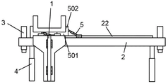
图1是本发明的滑轨Ⅱ结构示意图。Fig. 1 is a schematic diagram of the structure of the slide rail II of the present invention.
图2是本发明的滑动支座结构示意图。Fig. 2 is a schematic diagram of the structure of the sliding bearing of the present invention.
图3是本发明的微调装置结构示意图。Fig. 3 is a structural schematic diagram of the trimming device of the present invention.
图4是本发明的板块Ⅰ结构示意图。Fig. 4 is a schematic diagram of the structure of plate I of the present invention.
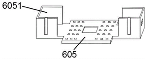
图5是本发明的板块Ⅱ结构示意图。Fig. 5 is a schematic diagram of the structure of plate II of the present invention.
图6是本发明的板块Ⅲ结构示意图。Fig. 6 is a schematic diagram of the structure of plate III of the present invention.
图7是本发明的承台结构示意图。Fig. 7 is a structural schematic diagram of the platform of the present invention.
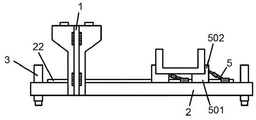
图8是本发明装置使用方法的初始安装示意图。Fig. 8 is a schematic diagram of the initial installation of the method of using the device of the present invention.
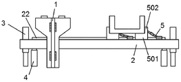
图9是本发明装置使用方法的更换下顶升油缸示意图。Fig. 9 is a schematic diagram of replacing the lower jacking oil cylinder in the method of using the device of the present invention.
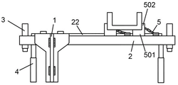
图10是本发明装置使用方法的桥梁上升桥墩顶部示意图。Fig. 10 is a schematic diagram of the top of the rising pier of the bridge in the method of using the device of the present invention.
图11是本发明装置使用方法的桥梁安装于支座示意图。Fig. 11 is a schematic diagram of the installation of the bridge on the support in the method of using the device of the present invention.
附图标记:1-滑轨Ⅰ,2-滑轨Ⅱ,21-滑槽Ⅰ,22-滑条,3-上顶升油缸,4-下顶升油缸,5-滑动支座,501-底座,502-挡板,503-滑槽Ⅱ,6-微调装置,601-千斤顶Ⅰ,602-千斤顶Ⅱ,603-千斤顶Ⅲ,604-板块Ⅰ,6041-L型板,6042-凸块,605-板块Ⅱ,6051-U型板Ⅰ,606-板块Ⅲ,6061-空心柱,6062-U型板Ⅱ,7-液压爬行器,8-承台,9-液压泵控制系统。Reference signs: 1-sliding rail Ⅰ, 2-sliding rail Ⅱ, 21-sliding groove Ⅰ, 22-sliding bar, 3-upper jacking cylinder, 4-lower jacking cylinder, 5-sliding support, 501-base , 502-baffle plate, 503-chute Ⅱ, 6-fine adjustment device, 601-jack Ⅰ, 602-jack Ⅱ, 603-jack Ⅲ, 604-plate Ⅰ, 6041-L type plate, 6042-bump, 605- Plate II, 6051-U-shaped plate I, 606-plate III, 6061-hollow column, 6062-U-shaped plate II, 7-hydraulic crawler, 8-cap, 9-hydraulic pump control system.
具体实施方式Detailed ways
下面结合附图对本发明作进一步说明。The present invention will be further described below in conjunction with accompanying drawing.
实施例1:Example 1:
一种轻轨轨道梁连续顶升安装装置,包括滑轨Ⅰ1、滑轨Ⅱ2、上顶升油缸3、下顶升油缸4、滑动支座5、微调装置6、液压爬行器7、承台8和液压泵控制系统9;A light rail track beam continuous jacking installation device, including slide rail I1, slide rail II2, upper jacking
所述的滑轨Ⅱ2一侧设有与滑轨Ⅰ1相匹配的滑槽Ⅰ21;所述的滑轨Ⅱ2顶部设有滑条22;One side of the slide rail II2 is provided with a slide groove I21 matching the slide rail I1; the top of the slide rail II2 is provided with a
所述的上顶升油缸3呈倒立式固定在滑轨Ⅱ2的两端;The upper jacking
所述的滑动支座5包括底座501,底座501上两侧均设有挡板502;所述的底座501底部设有与滑条22相匹配的滑槽Ⅱ503;The sliding
所述的微调装置6安装在滑动支座5的底座501上;所述的微调装置6包括一组千斤顶Ⅰ601、一组千斤顶Ⅱ602、一组千斤顶Ⅲ603、板块Ⅰ604、板块Ⅱ605和板块Ⅲ606;The fine-
所述的板块Ⅰ604上设有两组固定装置;所述的固定装置包括两个L型板6041,L型板6041竖直段正对;所述的板块Ⅰ604在两组固定装置之间设有凸块6042;There are two sets of fixing devices on the plate I604; the fixing devices include two L-shaped
所述的板块Ⅱ605的中部和板块Ⅲ606的中部均设有孔Ⅰ,孔Ⅰ尺寸大于凸块6042尺寸;所述的板块Ⅱ605两端设有直臂Ⅰ;所述的直臂Ⅰ上设有U型板Ⅰ6051;所述的U型板Ⅰ6051的底部设有孔Ⅱ;Both the middle part of the plate II 605 and the middle part of the
所述的板块Ⅲ606两侧设有与孔Ⅱ相匹配的直臂Ⅱ;与直臂Ⅱ同侧的所述的板块Ⅲ606的两端上各设有一组空心柱6061;两组所述的空心柱6061均连接有U型板Ⅱ6062;The two sides of the
所述的板块Ⅱ605上的孔Ⅰ套接在板块Ⅰ604的凸块6042上;所述的板块Ⅲ在606板块Ⅱ605上面;所述的板块Ⅲ606上的孔Ⅰ套接在板块Ⅰ604的凸块6042上;所述的板块Ⅲ606两端的直臂Ⅱ穿过板块Ⅲ606两侧的孔Ⅱ;The hole I on the plate II 605 is socketed on the
所述的千斤顶Ⅰ601的固定端固接在凸块6042上,活动端正对U型板Ⅱ6062底部;所述的千斤顶Ⅱ602位于空心柱6061之间并且其固定端固定在板块Ⅲ606上;所述的千斤顶Ⅲ603固定端固定在L型板6041竖直段,活动端正对U型板Ⅰ6051侧部;The fixed end of the jack I 601 is fixed on the
所述的液压爬行器7一端与微调装置6连接,另一端安装在滑轨Ⅱ2的滑条22上;One end of the hydraulic crawler 7 is connected to the fine-
所述的承台8包括承台板801;所述的承台板(801)底部设有与空心柱6061匹配套接的承台杆802。The
所述的液压泵控制系统9包括主控制台、控制器和泵站;所述的控制器分别与主控制台、液压爬行器7和泵站连接;所述的泵站分别与千斤顶Ⅰ601、千斤顶Ⅱ602和千斤顶Ⅲ603连接。The hydraulic pump control system 9 includes a main console, a controller and a pumping station; the controller is connected to the main console, the hydraulic crawler 7 and the pumping station respectively; the pumping station is connected to the jack I601, the jack II602 is connected with jack III603.
实施例2:Example 2:
本实施例与实施例1不同之处仅在于,所述的滑轨Ⅰ1两端的两侧设有固定板,固定板上设有若干个孔;螺栓穿过孔使固定板和滑轨Ⅰ1固定在桥墩两侧。The only difference between this embodiment and
实施例3:Example 3:
本实施例与实施例2不同之处仅在于,所述的U型板Ⅰ6051两侧设有卡槽Ⅰ;千斤顶Ⅲ603的伸缩端伸长时卡入U型板Ⅰ6051处的卡槽Ⅰ。The only difference between this embodiment and the second embodiment is that the two sides of the U-shaped plate I 6051 are provided with slots I; when the telescopic end of the
实施例4:Example 4:
本实施例与实施例3不同之处仅在于,所述的U型板Ⅱ6062底部设有卡槽Ⅱ;千斤顶Ⅰ601的伸缩端伸长时卡入U型板Ⅱ6062处的卡槽Ⅱ。The only difference between this embodiment and
实施例5:Example 5:
本实施例与实施例4不同之处仅在于,所述的板块Ⅰ604和板块Ⅱ605的上面均设有若干半圆槽;所述的半圆槽内均匹配一颗滚珠;板块Ⅰ604、板块Ⅱ605和板块Ⅲ606之间发生相对滑动时,滚珠滚动减少摩擦阻力。The only difference between this embodiment and
上述实施例的轻轨轨道梁连续顶升安装装置的使用方法:The method of using the light rail track beam continuous jacking installation device of the above embodiment:
初始安装:将滑轨Ⅰ1固定在桥墩的两侧;将滑轨Ⅱ2置于桥墩底部,滑槽Ⅰ21与滑轨Ⅰ1配合使用;滑轨Ⅱ2上有两个滑动支座5,将滑动支座5的底座501的滑槽Ⅱ503置于滑条22上配合使用;Initial installation: fix the slide rail Ⅰ1 on both sides of the pier; place the slide rail Ⅱ2 at the bottom of the pier, and use the chute Ⅰ21 with the slide rail Ⅰ1; there are two sliding
桥梁浇筑成形:将承台8的承台杆802套入空心柱6061内,将两根轨道梁的两端分别架在两桥墩处的承台板801和底座501上,在两根轨道梁之间安装钢构并浇筑混凝土,形成桥梁;Bridge pouring and forming: insert the
更换下顶升油缸:通过启动滑轨Ⅱ2两端的上顶升油缸3,使得滑轨Ⅱ2两端同步上升,上升到下顶升油缸4的原始高度停止上顶升油缸3,将下顶升油缸4安装在滑轨Ⅱ2底部,撤掉上顶升油缸3完成力系转换;Replace the lower jacking cylinder: start the upper jacking
桥梁上升桥墩顶部:启动下顶升油缸4将滑轨Ⅱ2上升到桥墩顶部,通过控制器控制液压爬行器7,当液压爬行器7的油缸伸出时,其夹块夹紧滑条;当液压爬行器7的油缸收缩时,其夹块松开滑条,与油缸同方向移动;Lifting the top of the pier of the bridge: start the lower jacking
桥梁定位:液压爬行器7将桥梁移动到桥墩上的支座附近时,调好液压泵控制系统9的主控制台参数,通过液压泵控制系统9的控制器控制微调装置6,启动板块Ⅲ606上的千斤顶Ⅱ602,控制器控制泵站给千斤顶Ⅱ602输送压力,将承台8和桥梁竖向移动,通过液压泵控制系统9的控制器启动凸块6042上的千斤顶Ⅰ601,千斤顶Ⅰ601伸长时推动U型板Ⅱ6062,U型板Ⅱ6062带动板块Ⅲ606在板块Ⅱ605上横向移动,板块Ⅲ606两侧的直臂Ⅱ在U型板Ⅰ6051的孔Ⅱ内横向移动,则空心柱6061上的承台8和桥梁也随之横向移动;通过液压泵控制系统9的控制器启动L型板6041竖直段上的千斤顶Ⅲ603,千斤顶Ⅲ603伸长时推动U型板Ⅰ6051,U型板Ⅰ6051带动板块Ⅱ605和板块Ⅲ606在板块Ⅰ604上前后移动,则板块Ⅲ606的空心柱6061上的承台8和桥梁也随之前后移动;Bridge positioning: when the hydraulic crawler 7 moves the bridge to the vicinity of the support on the pier, adjust the parameters of the main console of the hydraulic pump control system 9, control the fine-
桥梁安装于支座:通过液压泵控制系统计算,调整桥梁的竖向、横向和前后位置使其对应支座后,通过控制器控制下顶升油缸4收缩,桥梁下降置于支座上,完成安装工作。The bridge is installed on the support: through the calculation of the hydraulic pump control system, adjust the vertical, horizontal and front and rear positions of the bridge to correspond to the support, and then the jacking
以上实施例仅为本发明的示例性实施例,不用于限制本发明,本发明的保护范围由权利要求书限定。本领域人员可以在本发明的实质和保护范围内,对本发明做出各种修改或等同替换,这种修改或等同替换也应视为落在本发明的保护范围内。The above embodiments are only exemplary embodiments of the present invention, and are not intended to limit the present invention, and the protection scope of the present invention is defined by the claims. Those skilled in the art can make various modifications or equivalent replacements to the present invention within the spirit and protection scope of the present invention, and such modifications or equivalent replacements should also be deemed to fall within the protection scope of the present invention.
Claims (4)
Priority Applications (1)
| Application Number | Priority Date | Filing Date | Title |
|---|---|---|---|
| CN202110116115.7A CN112921718B (en) | 2021-01-28 | 2021-01-28 | Light rail track beam continuous jacking installation device and its use method |
Applications Claiming Priority (1)
| Application Number | Priority Date | Filing Date | Title |
|---|---|---|---|
| CN202110116115.7A CN112921718B (en) | 2021-01-28 | 2021-01-28 | Light rail track beam continuous jacking installation device and its use method |
Publications (2)
| Publication Number | Publication Date |
|---|---|
| CN112921718A CN112921718A (en) | 2021-06-08 |
| CN112921718B true CN112921718B (en) | 2022-11-01 |
Family
ID=76167713
Family Applications (1)
| Application Number | Title | Priority Date | Filing Date |
|---|---|---|---|
| CN202110116115.7A Expired - Fee Related CN112921718B (en) | 2021-01-28 | 2021-01-28 | Light rail track beam continuous jacking installation device and its use method |
Country Status (1)
| Country | Link |
|---|---|
| CN (1) | CN112921718B (en) |
Families Citing this family (1)
| Publication number | Priority date | Publication date | Assignee | Title |
|---|---|---|---|---|
| CN117626728A (en) * | 2023-10-17 | 2024-03-01 | 中铁五局集团有限公司 | A construction method for installing and positioning horizontal supports and embedded panels for slide rails |
Citations (6)
| Publication number | Priority date | Publication date | Assignee | Title |
|---|---|---|---|---|
| JPH11172626A (en) * | 1997-12-16 | 1999-06-29 | Ishikawajima Harima Heavy Ind Co Ltd | Bridge girder continuous feeder |
| JP2004332222A (en) * | 2003-04-30 | 2004-11-25 | Mitsubishi Heavy Ind Ltd | Rebuilding construction method for bridge and bridge |
| CN102704705A (en) * | 2012-06-06 | 2012-10-03 | 河北省建筑科学研究院 | Building long-stroke redescending-free multi-point synchronous jacking method |
| CN106368125A (en) * | 2016-08-29 | 2017-02-01 | 重庆单轨交通工程有限责任公司 | Adjusting method and adjusting device for line shape of straddle type single-track traffic route |
| CN210684475U (en) * | 2019-08-05 | 2020-06-05 | 中铁二十局集团第一工程有限公司 | Hydraulic jacking device for bridge jacking construction based on inverted jack |
| CN111501438A (en) * | 2020-05-11 | 2020-08-07 | 中铁八局集团有限公司 | Continuous rigid frame PC track beam line shape adjusting construction method |
Family Cites Families (10)
| Publication number | Priority date | Publication date | Assignee | Title |
|---|---|---|---|---|
| JP2000230205A (en) * | 1999-02-09 | 2000-08-22 | Shimizu Corp | Elevated track construction method and equipment |
| CN2934344Y (en) * | 2006-08-11 | 2007-08-15 | 重庆大学 | Light railway girder lifting device |
| KR101212729B1 (en) * | 2011-04-25 | 2012-12-14 | 유니슨이테크 주식회사 | Apparatus for manufacturing curvilineal track beam for monorail in mold room |
| CN102518312A (en) * | 2011-12-28 | 2012-06-27 | 中国海洋石油总公司 | Synchronous jacking accurate in-place installation process for large equipment |
| CN104894977B (en) * | 2015-06-02 | 2016-09-07 | 中铁二十三局集团有限公司 | A kind of method utilizing three-dimensional adjustable jack device to set up magnetic levitation track girder |
| CN205576749U (en) * | 2016-04-20 | 2016-09-14 | 重庆水利电力职业技术学院 | Pontic roof beam structure promotes and rackwork |
| CN109680568B (en) * | 2019-02-28 | 2024-07-26 | 中建五局土木工程有限公司 | Track beam linear adjustment device and method |
| CN211472144U (en) * | 2019-07-29 | 2020-09-11 | 中建五局土木工程有限公司 | Turntable temporary support device |
| CN211256687U (en) * | 2019-09-29 | 2020-08-14 | 柳州东方工程橡胶制品有限公司 | Straddle type monorail track beam linear adjusting system |
| CN110607751B (en) * | 2019-09-29 | 2024-03-01 | 柳州东方工程橡胶制品有限公司 | Straddle type monorail track beam line type adjusting system and adjusting method thereof |
-
2021
- 2021-01-28 CN CN202110116115.7A patent/CN112921718B/en not_active Expired - Fee Related
Patent Citations (6)
| Publication number | Priority date | Publication date | Assignee | Title |
|---|---|---|---|---|
| JPH11172626A (en) * | 1997-12-16 | 1999-06-29 | Ishikawajima Harima Heavy Ind Co Ltd | Bridge girder continuous feeder |
| JP2004332222A (en) * | 2003-04-30 | 2004-11-25 | Mitsubishi Heavy Ind Ltd | Rebuilding construction method for bridge and bridge |
| CN102704705A (en) * | 2012-06-06 | 2012-10-03 | 河北省建筑科学研究院 | Building long-stroke redescending-free multi-point synchronous jacking method |
| CN106368125A (en) * | 2016-08-29 | 2017-02-01 | 重庆单轨交通工程有限责任公司 | Adjusting method and adjusting device for line shape of straddle type single-track traffic route |
| CN210684475U (en) * | 2019-08-05 | 2020-06-05 | 中铁二十局集团第一工程有限公司 | Hydraulic jacking device for bridge jacking construction based on inverted jack |
| CN111501438A (en) * | 2020-05-11 | 2020-08-07 | 中铁八局集团有限公司 | Continuous rigid frame PC track beam line shape adjusting construction method |
Also Published As
| Publication number | Publication date |
|---|---|
| CN112921718A (en) | 2021-06-08 |
Similar Documents
| Publication | Publication Date | Title |
|---|---|---|
| CN108330842B (en) | Bridge girder erection machine for erection construction of large-span reinforced concrete composite girder and construction method | |
| WO2022142193A1 (en) | Construction method for large-span thin-wall concrete sound barrier pouring trolley | |
| CN110158486B (en) | Bridge girder erection machine for erecting spliced wide beams and construction method | |
| CN110396942B (en) | Steel arch frame assembling and traversing system and method for upper bearing arch bridge construction | |
| CN110723677B (en) | Precast Beam Assisted Lifting Trolley | |
| CN110565983B (en) | Building jacking and shifting method | |
| CN108867316A (en) | Construction technology of walking-type jacking for long-span steel box girder of single-tower self-anchored suspension bridge | |
| CN206035507U (en) | Rectangle box culvert and for tunnel construction platform truck | |
| CN115961549A (en) | Rear-feeding beam type erection construction method for large-tonnage whole-section steel beam of cable-stayed bridge | |
| CN214993219U (en) | Concrete placement platform truck is contained to apron | |
| CN113832863B (en) | Method for double-frame bridge | |
| CN220813460U (en) | Low-clearance spliced wide bridge transverse-moving temporary pier auxiliary supporting system | |
| CN112144401B (en) | Bridge girder erection machine over-span method based on curve track and large longitudinal slope environment | |
| CN115928583A (en) | On-site temporary assembly and erection method of multi-segment steel box girder of cable-stayed bridge spanning multi-storey highway | |
| CN108004930A (en) | The construction method of vertical shift bowstring arch bridge | |
| CN108691277A (en) | Three-dimensional adjustment tool for positioning of segmental prefabricated assembled beams during erection | |
| CN115538326A (en) | Method for installing and correcting steel box girder of bridge | |
| CN120425727A (en) | Suspended wall installation system and construction method suitable for fully prefabricated assembled stations | |
| CN112921718A (en) | Continuous jacking and mounting device for light rail track beam and using method thereof | |
| CN110847045B (en) | Self-propelled portal template system for large-span arm bent cap of urban viaduct and construction method | |
| CN210917052U (en) | Large-tonnage pushing device | |
| CN116971277B (en) | Method for installing double-amplitude small-spacing curve steel box girder | |
| CN220550458U (en) | Construction device for sliding and installing plate girder on rail in height-limiting environment | |
| CN212245935U (en) | High mound girder steel top pushes away equipment hoist device | |
| CN216739080U (en) | Light rail track beam translation jacking device |
Legal Events
| Date | Code | Title | Description |
|---|---|---|---|
| PB01 | Publication | ||
| PB01 | Publication | ||
| SE01 | Entry into force of request for substantive examination | ||
| SE01 | Entry into force of request for substantive examination | ||
| GR01 | Patent grant | ||
| GR01 | Patent grant | ||
| CF01 | Termination of patent right due to non-payment of annual fee |
Granted publication date: 20221101 |
|
| CF01 | Termination of patent right due to non-payment of annual fee |