CN112921543B - A kind of energy-saving equipment for dyeing cheese yarn with ultra-low liquor ratio under normal temperature and normal pressure - Google Patents
A kind of energy-saving equipment for dyeing cheese yarn with ultra-low liquor ratio under normal temperature and normal pressure Download PDFInfo
- Publication number
- CN112921543B CN112921543B CN202110085196.9A CN202110085196A CN112921543B CN 112921543 B CN112921543 B CN 112921543B CN 202110085196 A CN202110085196 A CN 202110085196A CN 112921543 B CN112921543 B CN 112921543B
- Authority
- CN
- China
- Prior art keywords
- dyeing
- movable sleeve
- sleeve
- cheese
- ultra
- Prior art date
- Legal status (The legal status is an assumption and is not a legal conclusion. Google has not performed a legal analysis and makes no representation as to the accuracy of the status listed.)
- Active
Links
Images


Classifications
-
- D—TEXTILES; PAPER
- D06—TREATMENT OF TEXTILES OR THE LIKE; LAUNDERING; FLEXIBLE MATERIALS NOT OTHERWISE PROVIDED FOR
- D06B—TREATING TEXTILE MATERIALS USING LIQUIDS, GASES OR VAPOURS
- D06B3/00—Passing of textile materials through liquids, gases or vapours to effect treatment, e.g. washing, dyeing, bleaching, sizing, impregnating
- D06B3/04—Passing of textile materials through liquids, gases or vapours to effect treatment, e.g. washing, dyeing, bleaching, sizing, impregnating of yarns, threads or filaments
- D06B3/09—Passing of textile materials through liquids, gases or vapours to effect treatment, e.g. washing, dyeing, bleaching, sizing, impregnating of yarns, threads or filaments as packages, e.g. cheeses
-
- D—TEXTILES; PAPER
- D06—TREATMENT OF TEXTILES OR THE LIKE; LAUNDERING; FLEXIBLE MATERIALS NOT OTHERWISE PROVIDED FOR
- D06B—TREATING TEXTILE MATERIALS USING LIQUIDS, GASES OR VAPOURS
- D06B23/00—Component parts, details, or accessories of apparatus or machines, specially adapted for the treating of textile materials, not restricted to a particular kind of apparatus, provided for in groups D06B1/00 - D06B21/00
- D06B23/14—Containers, e.g. vats
- D06B23/18—Sealing arrangements
-
- D—TEXTILES; PAPER
- D06—TREATMENT OF TEXTILES OR THE LIKE; LAUNDERING; FLEXIBLE MATERIALS NOT OTHERWISE PROVIDED FOR
- D06B—TREATING TEXTILE MATERIALS USING LIQUIDS, GASES OR VAPOURS
- D06B3/00—Passing of textile materials through liquids, gases or vapours to effect treatment, e.g. washing, dyeing, bleaching, sizing, impregnating
- D06B3/34—Driving arrangements of machines or apparatus
Landscapes
- Engineering & Computer Science (AREA)
- Textile Engineering (AREA)
- Treatment Of Fiber Materials (AREA)
Abstract
Description
技术领域technical field
本发明属于印染领域,具体为一种常温常压下超低浴比筒子纱染色节能设备。The invention belongs to the field of printing and dyeing, in particular to an energy-saving device for cheese dyeing with an ultra-low bath ratio under normal temperature and pressure.
背景技术Background technique
超低浴比的染色设备,是印染领域所追寻的,在染色时不仅能够保证被染物质的印染质量,而且能够节省大量的水,但是目前的设备在进行染色的时候,都不是在常温常压下进行的,印染领域所规定的常温常压为温度小于罐体100℃时的温度和压力,而目前的设备都需要在高温高压的环境下进行,虽然能够达到提高染色时的目的,但是也产生了大量的能耗;而且由于印染时,染液流量小,导致染液在被染物质内流速慢,从而也降低了印染的速率。Dyeing equipment with ultra-low liquor ratio is what the printing and dyeing field pursues. It can not only ensure the printing and dyeing quality of the dyed material, but also save a lot of water. However, the current equipment is not dyed at room temperature. It is carried out under pressure. The normal temperature and pressure specified in the printing and dyeing field is the temperature and pressure when the temperature is lower than the tank body 100 ° C. However, the current equipment needs to be carried out in a high temperature and high pressure environment. Although it can achieve the purpose of improving the dyeing time, but It also produces a large amount of energy consumption; and due to the small flow rate of the dyeing solution during printing and dyeing, the flow rate of the dyeing solution in the dyed material is slow, thereby also reducing the rate of printing and dyeing.
目前市场应用类的染色设备还没有1:2.5—5的浴比的常温常压设备,节能低浴比的设备技术还没有先例;而最老的常温开口式染缸1:20左右的浴比早就不能适应绿色环保的要求。At present, there is no room temperature and pressure equipment with a bath ratio of 1:2.5-5 in the dyeing equipment used in the market, and there is no precedent for energy-saving and low bath ratio equipment technology; while the oldest open-type dyeing vat at room temperature has a bath ratio of about 1:20 earlier. Just can't adapt to the requirement of green environmental protection.
发明内容Contents of the invention
本发明的目的是针对以上问题,提供一种常温常压下超低浴比筒子纱染色节能设备,增强染液流速,提高印染速率,减少能耗。The object of the present invention is to solve the above problems and provide an energy-saving equipment for cheese dyeing with ultra-low liquor ratio under normal temperature and pressure, which can enhance the flow rate of dyeing liquor, increase the printing and dyeing rate, and reduce energy consumption.
为实现以上目的,本发明采用的技术方案是:一种常温常压下超低浴比筒子纱染色节能设备,包括罐体,所述罐体内设置印染腔,所述罐体的底部设置与所述印染腔连通的用于循环输送染液的循环机构,所述印染腔内固定设置与所述循环机构相连通的底座,In order to achieve the above objectives, the technical solution adopted by the present invention is: an energy-saving equipment for cheese dyeing with an ultra-low liquor ratio under normal temperature and pressure, including a tank body, a printing and dyeing chamber is arranged in the tank body, and the bottom of the tank body is arranged with the A circulation mechanism for circularly conveying dye liquor connected to the printing and dyeing chamber, a base connected to the circulation mechanism is fixedly installed in the printing and dyeing chamber,
所述底座的顶部固定设置与所述底座的内腔内可选择性连通的若干个出液管,所述出液管的外侧套接有活动套管,所述活动套管上设置与所述出液管表面上的排出孔可选择性的相连通的长槽型孔,所述活动套管的外侧放置筒子纱,每两个所述筒子纱之间设置套接在所述活动套管的外侧面上的隔套;The top of the base is fixedly provided with a number of liquid outlet pipes that can be selectively communicated with the inner cavity of the base, and the outer side of the liquid outlet pipe is sleeved with a movable sleeve, and the movable sleeve is provided with the The discharge hole on the surface of the liquid outlet pipe can be selectively connected to a long slot-shaped hole. The cheese is placed on the outside of the movable sleeve, and the sleeve is set between every two cheeses and connected to the movable sleeve. spacer on the outer side;
所述底座的顶面上设置驱动所述活动套管转动驱动机构,所述印染腔的侧壁上设置若干个支撑台,所述活动套管在转动的时候,通过所述支撑台的推动,使所述隔套对所述筒子纱进行挤压;The top surface of the base is provided with a drive mechanism to drive the movable sleeve to rotate, and several support platforms are arranged on the side wall of the printing and dyeing chamber. When the movable sleeve is rotating, it is pushed by the support platform. causing the spacer to squeeze the cheese;
所述活动套管的外侧设置将所述筒子纱完全密封的密封罩,所述密封罩的表面上设置若干个内外相通的阻尼孔,所述罐体的外侧面连接吸泵。The outer side of the movable sleeve is provided with a sealing cover which completely seals the cheese, the surface of the sealing cover is provided with several damping holes communicating with the inside and outside, and the outer surface of the tank body is connected with a suction pump.
进一步的,所述驱动机构包括固定设置于所述底座的顶部的撑座,所述撑座内转动设置第一齿轮,所述第一齿轮的转动轴上连接驱动源,所述底座的顶面上转动设置若干个中心对称的第二齿轮,所述第二齿轮与所述第一齿轮啮合,所述活动套管可拆卸的插入到所述第二齿轮内,并与所述活动套管之间能互相上下滑动。Further, the drive mechanism includes a support seat fixedly arranged on the top of the base, a first gear is rotated inside the support seat, a driving source is connected to the rotation shaft of the first gear, and the top surface of the base Several center-symmetrical second gears are arranged on the top, the second gears are meshed with the first gears, the movable sleeve is detachably inserted into the second gears, and can slide up and down each other.
进一步的,所述活动套管的顶部固定设置连接头,所述连接头与所述活动套管之间螺纹连接,所述连接头的顶部固定设置连接箱,所述连接箱的内腔内连通设置第一连接管和第二连接管,所述第二连接管贯穿所述出液管和所述活动套管,并伸入到所述出液管内,所述第一连接管的另外一端与所述密封罩的顶面之间互相连通。Further, the top of the movable casing is fixedly provided with a connecting head, and the connecting head is threadedly connected with the movable casing, and the top of the connecting head is fixedly provided with a connection box, and the inner cavity of the connection box communicates A first connecting pipe and a second connecting pipe are provided, the second connecting pipe runs through the liquid outlet pipe and the movable sleeve, and extends into the liquid outlet pipe, the other end of the first connecting pipe is connected to the The top surfaces of the sealing covers communicate with each other.
进一步的,所述活动套管上上下活动的设置限制板,所述限制板与最底部的所述隔套相接触,所述限制板的顶面上固定设置弹性的密封圈,所述密封圈的顶面与所述密封罩的底面之间互相接触,所述支撑台的顶面设置上下两层的台阶面,且最高的面和最低侧面之间通过斜面过渡,所述活动套管的底部设置与所述支撑台顶部的台阶面接触的滚轮。Further, a restricting plate is movable up and down on the movable sleeve, and the restricting plate is in contact with the spacer at the bottom, and an elastic sealing ring is fixedly arranged on the top surface of the restricting plate, and the sealing ring The top surface of the support platform is in contact with the bottom surface of the sealing cover. The top surface of the support platform is provided with upper and lower steps, and the highest surface and the lowest side are transitioned through a slope. The bottom of the movable sleeve A roller contacting with the step surface on the top of the support platform is provided.
进一步的,所述活动套管的底端设置扩口端,所述活动套管的扩口端与所述出液管之间设置密封套,所述出液管与所述活动套管之间能互相滑动且互相转动。Further, the bottom end of the movable sleeve is provided with a flared end, and a sealing sleeve is provided between the flared end of the movable sleeve and the liquid outlet pipe, and a sealing sleeve is provided between the liquid outlet pipe and the movable sleeve. Can slide and rotate with each other.
进一步的,所述罐体的顶部设置密封的顶盖,所述顶盖的底面上弹性设置上下滑动的夹紧套,所述夹紧套上转动设置与所述连接箱相接触的转动套,所述转动套对所述连接箱提供挤压力。Further, a sealed top cover is provided on the top of the tank body, and a clamping sleeve that slides up and down is elastically provided on the bottom surface of the top cover, and a rotating sleeve that is in contact with the connection box is rotated on the clamping sleeve, The rotating sleeve provides extrusion force to the connection box.
进一步的,所述顶盖的顶部铰接连接第一连杆,所述罐体的侧壁上铰接设置第二连杆,所述第二连杆的另外一端与所述第一连杆的折弯处之间互相铰链连接,所述第一连杆的另外一端设置手柄。Further, the top of the top cover is hingedly connected to the first connecting rod, and the side wall of the tank body is hingedly provided with a second connecting rod, and the other end of the second connecting rod is connected to the bent portion of the first connecting rod. The places are hingedly connected to each other, and the other end of the first connecting rod is provided with a handle.
所述隔套包括隔板和滑套,所述隔板和所述滑套之间互相固定连接在一起,所述隔板的表面上设置上下贯通的通孔,所述滑套的上端外侧面和下端内侧面设置台阶,所述滑套上设置将所述滑套分割成若干片的分割槽。The spacer includes a partition and a sliding sleeve, the partition and the sliding sleeve are fixedly connected to each other, the surface of the partition is provided with a through hole that penetrates up and down, and the outer surface of the upper end of the sliding sleeve Steps are provided on the inner side of the lower end, and the sliding sleeve is provided with dividing grooves for dividing the sliding sleeve into several pieces.
进一步的,所述吸泵与所述罐体所连接的管道上设置竖直向上的弯折管道。Further, the pipeline connecting the suction pump and the tank body is provided with a vertically upward bent pipeline.
进一步的,所述底座的内腔内设置温控器。Further, a temperature controller is set in the inner cavity of the base.
本发明的有益效果:本发明提供了一种常温常压下超低浴比筒子纱染色节能设备,1、通过设置密封罩,将筒子纱进行隔绝,通过密封罩的内外负压,使染液快速的向低压区域流动,使染液能够快速的穿过筒子纱,从而增加对筒子纱的染色速率。Beneficial effects of the present invention: the present invention provides an energy-saving device for cheese dyeing with ultra-low liquor ratio under normal temperature and pressure. Fast flow to the low-pressure area, so that the dye liquor can quickly pass through the package yarn, thereby increasing the dyeing rate of the package yarn.
2、通过设置隔套,使每一个筒子纱单独被隔离开来,使在染色时,不会缠绕在一起,通过其自身的转动带动上下方向上的挤压运动,使存在于筒子纱内的染液能够在饱和的状态下排出,也能够使染液快速的流动,增加染色速率。2. By setting a spacer, each package is isolated separately, so that it will not be entangled during dyeing, and the extrusion movement in the up and down direction is driven by its own rotation, so that the yarn existing in the package The dye liquor can be discharged in a saturated state, and it can also make the dye liquor flow quickly to increase the dyeing rate.
3、通过机械运动的配合,使染液能够达到超低浴比的染色要求,减少设备能耗和染色时间,率先将染色技术在(筒子纱、经轴、散纤维、染布等)染整设备技术的模式下以及节能技术的大环境下,开发领先于高温高压低浴比的,节能的常温常压低浴比系列染色设备。3. Through the cooperation of mechanical movement, the dye liquor can meet the dyeing requirements of ultra-low bath ratio, reduce equipment energy consumption and dyeing time, and take the lead in dyeing and finishing dyeing technology in (cheese, warp beam, loose fiber, dyed cloth, etc.) Under the mode of equipment technology and the general environment of energy-saving technology, the development of high-temperature, high-pressure, low-bath-ratio, energy-saving dyeing equipment at room temperature, normal pressure and low liquor ratio series.
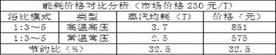
4、工艺时间也较高温高压的工艺时间缩短每个工艺将近1小时,这就是温度的优势所带来的节约时间;按照年产量10000吨企业成本计算节能效果相当可观,以单位(活性染料、酸性染料)染色成本优势如下:4. The process time is also shorter than the process time of high temperature and high pressure by nearly 1 hour per process, which is the time saving brought by the advantage of temperature; the energy saving effect is quite considerable based on the annual output of 10,000 tons of enterprise costs, and the unit (reactive dye, Acid dyes) dyeing cost advantages are as follows:
附图说明Description of drawings
图1为本发明整体结构示意图;Fig. 1 is a schematic diagram of the overall structure of the present invention;
图2为图1中A-A方向的剖视示意图;Fig. 2 is the sectional schematic view of A-A direction in Fig. 1;
图3为图1中B处的局部放大结构示意图;Fig. 3 is a schematic diagram of a partially enlarged structure at B in Fig. 1;
图4为图1中C处的局部放大结构示意图;FIG. 4 is a schematic diagram of a partially enlarged structure at C in FIG. 1;
图5为图1中D处的局部放大结构示意图;FIG. 5 is a schematic diagram of a partially enlarged structure at D in FIG. 1;
图6为图2中E-E方向的剖视示意图;Fig. 6 is a schematic cross-sectional view of E-E direction in Fig. 2;
图7为隔套17的立体结构示意图。FIG. 7 is a schematic perspective view of the three-dimensional structure of the
图中所述文字标注表示为:10、罐体;11、印染腔;12、底座;13、出液管;14、活动套管;15、长槽型孔;16、筒子纱;17、隔套;171、隔板;172、滑套;18、支撑台;19、密封罩;20、阻尼孔;21、吸泵;22、支撑座;23、第一齿轮;24、第二齿轮;25、顶盖;26、夹紧套;27、连接头;28、连接箱;29、第一连接管;30、第二连接管;31、限制板;32、密封圈;33、密封套;34、转动套;35、第一连杆;36、第二连杆;37、温控器。The text marked in the figure is expressed as: 10, tank body; 11, printing and dyeing chamber; 12, base; 13, liquid outlet pipe; 14, movable sleeve; 15, long slot hole; Cover; 171, partition; 172, sliding sleeve; 18, support platform; 19, sealing cover; 20, damping hole; 21, suction pump; 22, support seat; 23, first gear; 24, second gear; 25 , top cover; 26, clamping sleeve; 27, connecting head; 28, connecting box; 29, first connecting pipe; 30, second connecting pipe; 31, limiting plate; 32, sealing ring; 33, sealing sleeve; 34 , rotating sleeve; 35, the first connecting rod; 36, the second connecting rod; 37, the thermostat.
具体实施方式Detailed ways
为了使本领域技术人员更好地理解本发明的技术方案,下面结合附图对本发明进行详细描述,本部分的描述仅是示范性和解释性,不应对本发明的保护范围有任何的限制作用。In order to enable those skilled in the art to better understand the technical solution of the present invention, the present invention will be described in detail below in conjunction with the accompanying drawings. The description in this part is only exemplary and explanatory, and should not have any limiting effect on the protection scope of the present invention. .
如说明书附图1-7所示,本发明的具体结构为:一种常温常压下超低浴比筒子纱染色节能设备,包括罐体10,所述罐体10内设置印染腔11,所述罐体10的底部设置与所述印染腔11连通的用于循环输送染液的循环机构,所述循环机构主要是由输送泵对染液进行循环抽吸工作,所述印染腔11内固定设置与所述循环机构相连通的底座12,As shown in the accompanying drawings 1-7 of the description, the specific structure of the present invention is: an energy-saving equipment for cheese dyeing with an ultra-low liquor ratio under normal temperature and pressure, comprising a
所述底座12的顶部固定设置与所述底座12的内腔内可选择性连通的若干个出液管13,优选六个,出液管13与底座12内腔的通断由设置在底座12的底部的控制阀进行控制,控制阀打开时,出液管13和底座12的内腔连通,所述出液管13的外侧套接有活动套管14,所述活动套管14上设置与所述出液管13表面上的排出孔可选择性的相连通的长槽型孔15,长槽型孔15沿活动套管14的轴线方向上的长度长于与活动套管14轴线方向垂直的长度,所述活动套管14的外侧放置筒子纱16,每两个所述筒子纱16之间设置套接在所述活动套管14的外侧面上的隔套17,所述隔套17的数量与筒子纱16的数量相对应,且每两个隔套17之间互相套接在一起;The top of the
所述底座12的顶面上设置驱动所述活动套管14转动驱动机构,所述印染腔11的侧壁上设置若干个支撑台18,所述活动套管14在转动的时候,通过所述支撑台18的推动,使活动套管14相对于出液管13在上下的方向上滑动,从而带动隔套17使所述隔套17对所述筒子纱16进行挤压,隔套17在对筒子纱16进行挤压的时候,使筒子纱16内的染液能快速的流动和排出;The top surface of the
所述活动套管14的外侧设置将所述筒子纱16完全密封的密封罩19,所述密封罩19的表面上设置若干个内外相通的阻尼孔20,所述罐体10的外侧面连接吸泵21,当吸泵21启动之后,抽吸密封罩19外侧的空气,使密封罩19的内外两侧形成负压,在压力差的作用下,筒子纱16内的染液迅速穿过筒子纱16,从而实现提高染液在筒子纱16内的流动速度。The outer side of the
优选的,如说明书附图1、3所示,所述驱动机构包括固定设置于所述底座12的顶部的撑座22,所述撑座22内转动设置第一齿轮23,所述第一齿轮23的转动轴上连接驱动源,驱动源为固定设置在顶盖25的顶部的电动机,电动机的输出轴和第一齿轮23的转动轴上通过能够互相分开的一对摩擦盘进行传动连接,连接于第一齿轮23的转动轴上的摩擦盘能够相对的上下弹性浮动,主要是由弹簧提供上下浮动的弹力,在两个摩擦盘相互接触之后,弹簧提供摩擦盘之间的压力,所述底座12的顶面上转动设置若干个中心对称的第二齿轮24,所述第二齿轮24与所述第一齿轮23啮合,所述活动套管14可拆卸的插入到所述第二齿轮24内,并与所述活动套管14之间能互相上下滑动,活动套管14和第二齿轮24之间只能上下互相滑动,但是不能够互相发生转动,在电动机带动第一齿轮23转动的时候,第一齿轮23带动第二齿轮24转动,从而带动活动套管14一起发生旋转。Preferably, as shown in accompanying drawings 1 and 3 of the specification, the drive mechanism includes a
优选的,如说明书附图1、5所示,所述活动套管14的顶部固定设置连接头27,所述连接头27与所述活动套管14之间螺纹连接,所述连接头27的顶部固定设置连接箱28,所述连接箱28的内腔内连通设置第一连接管29和第二连接管30,所述第二连接管30贯穿所述出液管13和所述活动套管14,并伸入到所述出液管13内,所述第一连接管29的另外一端与所述密封罩19的顶面之间互相连通,通过第二连接管30插入到出液管13内,能够将出液管13内的染液从出液管13内经过第二连接管30、连接箱28和第一连接管29引入到最顶部的筒子纱16的顶面上进行喷撒,从而能够防止最顶部的筒子纱16在印染时出现印染不均匀的情况。Preferably, as shown in accompanying drawings 1 and 5 of the description, the top of the
优选的,如说明书附图1、3所示,所述活动套管14上上下活动的设置限制板31,限制板31与活动套管14之间不能互相转动,所述限制板31与最底部的所述隔套17相接触,所述限制板31的顶面上固定设置弹性的密封圈32,所述密封圈32的顶面与所述密封罩19的底面之间互相接触,所述支撑台18的顶面设置上下两层的台阶面,且最高的面和最低侧面之间通过斜面过渡,所述活动套管14的底部设置与所述支撑台18顶部的台阶面接触的滚轮,当活动套管14带动隔套17和筒子纱16一起转动时,使限制板31底部的滚轮在支撑台18的台阶面上滚动,从而使支撑台18的台阶面推动限制板31上下方向的运动,从而使筒子纱16在上下的方向上进行挤压,密封圈32能够发生弹性形变,使限制板31在上下方向上活动的时候,将使密封罩19的内侧部分完全封闭。Preferably, as shown in accompanying drawings 1 and 3 of the specification, the
优选的,如说明书附图1、3所示,所述活动套管14的底端设置扩口端,所述活动套管14的扩口端与所述出液管13之间设置密封套33,密封套33对活动套管14和出液管13之间的间隙密封,所述出液管13与所述活动套管14之间能互相滑动且互相转动,出液管13和活动套管14之间互相转动的时候,使出液管13上的排出孔相对筒子纱16的在上下位置上发生变化,从而使出液管13上的排出孔对筒子纱16的喷出的染液的范围更大。Preferably, as shown in Figures 1 and 3 of the specification, the bottom end of the
优选的,如说明书附图1所示,所述罐体10的顶部设置密封的顶盖25,所述顶盖25的底面上弹性设置上下滑动的夹紧套26,夹紧套26和顶盖25之间设置推动夹紧套26上下弹性活动的弹簧,所述夹紧套26上转动设置与所述连接箱28相接触的转动套34,所述转动套34对所述连接箱28提供挤压力。Preferably, as shown in Figure 1 of the specification, a sealed
优选的,如说明书附图1所示,所述顶盖25的顶部铰接连接第一连杆35,所述罐体10的侧壁上铰接设置第二连杆36,所述第二连杆36的另外一端与所述第一连杆35的折弯处之间互相铰链连接,所述第一连杆35的另外一端设置手柄,通过拉动第一连杆35上设置的手柄,使顶盖25被打开。Preferably, as shown in Figure 1 of the specification, the top of the
优选的,如说明书附图1、4、5、7所示,所述隔套17包括隔板171和滑套172,所述隔板171和所述滑套172之间互相固定连接在一起,所述隔板171的表面上设置上下贯通的通孔,通孔主要能便于上侧的筒子纱16上流出的染液流入到下侧的筒子纱16上,以便于染液侧充分利用,所述滑套172的上端外侧面和下端内侧面设置台阶,每一个下侧的滑套172的上端的台阶和每一个上侧的滑套172的下端的台阶之间能够互相配合,且不互相发生干涉,所述滑套172上设置将所述滑套172分割成若干片的分割槽,分隔槽的数量和长槽型孔15的数量相对应,且位置也相对应。Preferably, as shown in Figures 1, 4, 5, and 7 of the specification, the
优选的,如说明书附图1所示,所述吸泵21与所述罐体10所连接的管道上设置竖直向上的弯折管道,向上弯折的管道能够保证染液被吸入之后,能够自动的回流到印染腔11内。Preferably, as shown in the accompanying drawing 1 of the specification, the pipeline connected to the
优选的,如说明书附图1、3所示,所述底座12的内腔内设置温控器37,温控器37主要是调节底座12内的染液的温度最高不超过罐体100℃。Preferably, as shown in Figures 1 and 3 of the specification, a
本发明的使用原理是:在需要对筒子纱16进行染色的时候,首先将筒子纱16和隔套17套在活动套管14上,然后使用密封罩19和活动套管14拧紧,将筒子纱16和隔套17罩住,The principle of use of the present invention is: when the
然后将活动套管14插到到出液管13上,盖上顶盖25,夹紧套26和转动套34将连接箱28压住,使活动套管14的上下两端都得到支撑,准备进行染色,Then the
启动吸泵21,对印染腔11内进行抽取空气,启动顶盖25顶部的电动机,电动机带动第一齿轮23和第二齿轮24转动,第二齿轮24转动的时候带动活动套管14转动,启动循环机构,使染液向底座12和出液管13内输送,染液在底座12内通过温控器37进行温度的调节控制,输入到染液经过出液管13上的排出孔经由活动套管14和隔套17喷撒到筒子纱16上,Start the
在活动套管14转动的时候,通过限制板31底部的滚轮在支撑台18上运动,使限制板31带动隔套17和筒子纱16上下方向的运动,从而使筒子纱16被进行挤压,使筒子纱16内的染液的流动速度增加,在活动套管14上下运动的时候,出液管13上排出孔喷出的染液在筒子纱16上的位置能够在上下的一个范围内变化,从而实现跟大范围的对筒子纱16上进行喷撒染液,When the
在吸泵21抽取印染腔11内的空气后,密封罩19的内外两侧形成负压,从而使筒子纱16内的染液在压力差的作用下穿过筒子纱16并排出,After the
当印染完成之后,通过拉动第一连杆35,使顶盖25打开,然后向上将活动套管14从出液管13上取下。After the printing and dyeing is completed, the
需要说明的是,在本文中,术语“包括”、“包含”或者其任何其他变体意在涵盖非排他性的包含,从而使得包括一系列要素的过程、方法、物品或者设备不仅包括那些要素,而且还包括没有明确列出的其他要素,或者是还包括为这种过程、方法、物品或者设备所固有的要素。It should be noted that, in this document, the terms "comprising", "comprising" or any other variation thereof are intended to cover a non-exclusive inclusion such that a process, method, article or apparatus comprising a set of elements includes not only those elements, It also includes other elements not expressly listed, or elements inherent in the process, method, article, or apparatus.
本文中应用了具体个例对本发明的原理及实施方式进行了阐述,以上实例的说明只是用于帮助理解本发明的方法及其核心思想。以上所述仅是本发明的优选实施方式,应当指出,由于文字表达的有限性,而客观上存在无限的具体结构,对于本技术领域的普通技术人员来说,在不脱离本发明原理的前提下,还可以做出若干改进、润饰或变化,也可以将上述技术特征以适当的方式进行组合;这些改进润饰、变化或组合,或未经改进将发明的构思和技术方案直接应用于其它场合的,均应视为本发明的保护范围。In this paper, specific examples are used to illustrate the principle and implementation of the present invention. The description of the above examples is only used to help understand the method and core idea of the present invention. The above is only a preferred embodiment of the present invention. It should be pointed out that due to the limitation of literal expression, there are objectively unlimited specific structures. Under these circumstances, several improvements, modifications or changes can also be made, and the above-mentioned technical features can also be combined in an appropriate manner; these improvements, modifications, or combinations, or the idea and technical solution of the invention can be directly applied to other occasions without improvement should be regarded as the protection scope of the present invention.
Claims (9)
Priority Applications (1)
| Application Number | Priority Date | Filing Date | Title |
|---|---|---|---|
| CN202110085196.9A CN112921543B (en) | 2021-01-21 | 2021-01-21 | A kind of energy-saving equipment for dyeing cheese yarn with ultra-low liquor ratio under normal temperature and normal pressure |
Applications Claiming Priority (1)
| Application Number | Priority Date | Filing Date | Title |
|---|---|---|---|
| CN202110085196.9A CN112921543B (en) | 2021-01-21 | 2021-01-21 | A kind of energy-saving equipment for dyeing cheese yarn with ultra-low liquor ratio under normal temperature and normal pressure |
Publications (2)
| Publication Number | Publication Date |
|---|---|
| CN112921543A CN112921543A (en) | 2021-06-08 |
| CN112921543B true CN112921543B (en) | 2022-11-11 |
Family
ID=76164420
Family Applications (1)
| Application Number | Title | Priority Date | Filing Date |
|---|---|---|---|
| CN202110085196.9A Active CN112921543B (en) | 2021-01-21 | 2021-01-21 | A kind of energy-saving equipment for dyeing cheese yarn with ultra-low liquor ratio under normal temperature and normal pressure |
Country Status (1)
| Country | Link |
|---|---|
| CN (1) | CN112921543B (en) |
Families Citing this family (2)
| Publication number | Priority date | Publication date | Assignee | Title |
|---|---|---|---|---|
| CN115573123A (en) * | 2022-10-17 | 2023-01-06 | 浙江品控科技管理有限公司 | High color fastness filling equipment |
| CN119145142B (en) * | 2024-11-21 | 2025-04-18 | 江苏新凯奇纺织科技发展有限公司 | A low-water printing and dyeing device with uniform printing and dyeing and a printing and dyeing process thereof |
Family Cites Families (3)
| Publication number | Priority date | Publication date | Assignee | Title |
|---|---|---|---|---|
| CN203174342U (en) * | 2013-02-07 | 2013-09-04 | 广州番禺高勋染整设备制造有限公司 | Ultra-low bath ratio zipper dyeing machine |
| CN103088574B (en) * | 2013-02-07 | 2014-04-02 | 广州番禺高勋染整设备制造有限公司 | Ultralow liquor ratio zipper dyeing machine and dyeing process thereof |
| CN207419046U (en) * | 2017-11-01 | 2018-05-29 | 广州盟鸿染整设备有限公司 | Low bath raio multifunction dynamic overflow dyeing machine |
-
2021
- 2021-01-21 CN CN202110085196.9A patent/CN112921543B/en active Active
Also Published As
| Publication number | Publication date |
|---|---|
| CN112921543A (en) | 2021-06-08 |
Similar Documents
| Publication | Publication Date | Title |
|---|---|---|
| CN108943421B (en) | A gypsum board edge sealing device | |
| CN109234949B (en) | Vacuum dyeing device based on quick printing and dyeing of cloth | |
| CN108998911B (en) | Cloth dyeing machine for dip-dyeing cloth | |
| CN109281102A (en) | A kind of dyeing equipment for fabric printing and dyeing | |
| CN205975015U (en) | High -efficient cloth dyeing machine of environmental protection | |
| CN103526492A (en) | Single-yarn dyeing and sizing integrated machine | |
| CN203546406U (en) | Single yarn dyeing and sizing all-in-one machine | |
| CN112921543A (en) | Ultralow bath ratio cheese dyeing energy-saving equipment under normal temperature and normal pressure | |
| CN106868756B (en) | A padding stoving coil stock all-in-one for cloth | |
| CN116815435A (en) | Bleaching machine for processing spandex three-dimensional cloth and bleaching method thereof | |
| CN116695366A (en) | Environment-friendly all-cotton fabric printing and dyeing equipment and method | |
| CN110711668A (en) | Coiled material processing production line | |
| CN109162053A (en) | Quantitative cloth dyeing apparatus | |
| CN108914450A (en) | A kind of printing and dyeing of cloth extract integrated device with dyeing | |
| CN114855382B (en) | Clean energy-saving fabric printing and dyeing process | |
| CN216919707U (en) | An efficient and environmentally friendly jigger | |
| CN115074936B (en) | Dyeing soaking device with movable guiding function for textile printing and dyeing | |
| CN211591010U (en) | Calendering device for manufacturing homogeneous permeable floor | |
| CN109056228B (en) | Cloth dyeing machine | |
| CN207904546U (en) | A kind of uniform rolling mill assembly | |
| CN210916596U (en) | High-efficient spray-painting device for clothing production | |
| CN224119270U (en) | A dyeing machine that avoids fabric tangling | |
| CN108842325A (en) | A kind of tribute silk floss cleaning pressuring flat device | |
| CN216193320U (en) | Efficient is washing drying device for cotton yarn | |
| CN108998912B (en) | A pad dyeing equipment for improving the efficiency of dyeing cloth |
Legal Events
| Date | Code | Title | Description |
|---|---|---|---|
| PB01 | Publication | ||
| PB01 | Publication | ||
| SE01 | Entry into force of request for substantive examination | ||
| SE01 | Entry into force of request for substantive examination | ||
| GR01 | Patent grant | ||
| GR01 | Patent grant | ||
| TR01 | Transfer of patent right |
Effective date of registration: 20250422 Address after: 417100 Heyi Group, Luojiaping Community, Baima Town, Lianyuan City, Loudi City, Hunan Province Patentee after: Luo Xiangchun Country or region after: China Address before: 310000 Room 101, building 1, No.3 Fuwang Road, Renhe street, Yuhang District, Hangzhou City, Zhejiang Province Patentee before: Hangzhou Zhongzhi Textile Technology Co.,Ltd. Country or region before: China |
|
| TR01 | Transfer of patent right |