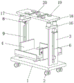
Building indoor decoration is with roof board hoisting device
Technical Field
The invention relates to the technical field of plate hoisting, in particular to a roof plate hoisting device for building interior decoration.
Background
Need carry out the operation of many aspects when carrying out interior decoration, wall ground and ceiling all need handle, and need carry out the handling to the roof panel when carrying out the roof operation to the installation of the panel to the roof has been made things convenient for.
There is certain drawback at the in-process that uses in the overhead hoist of current roof panel, once only can a panel of handling carry out the handling operation, unable polylith roof panel of handling simultaneously, very big influence the workman to the installation effectiveness of roof panel, and can not be fine carry out the rigidity to the panel of handling when installing, easily take place to rock at the in-process of installation, great influence the stability of roof plate when installing, make the workman easily produce the error when installing roof panel.
Disclosure of Invention
Aiming at the defects of the prior art, the invention provides a roof plate hoisting device for building interior decoration, which has the advantages of hoisting a plurality of roof plates simultaneously, fixing the positions of the roof plates simultaneously and greatly improving the stability of the roof plates during installation, and solves the problems in the background art.
The invention provides the following technical scheme: the utility model provides a building indoor decoration is with roof board overhead hoist, includes the base, two support risers of last fixed surface of base are connected with, be equipped with the loading board directly over the base, the loading board is located between two support risers, the equal fixedly connected with slider in both ends of loading board, the top fixedly connected with haulage rope of slider, the outside fixed surface that supports the riser is connected with the motor, the output shaft of motor runs through support riser and fixedly connected with receive and release the wheel, receive and release the top fixed connection of wheel and haulage rope.
Preferably, the top fixedly connected with mounting panel of support riser, the last fixed surface of mounting panel is connected with the hydraulic stem, the top fixedly connected with roof of hydraulic stem, the last fixed surface of roof is connected with a plurality of sucking disc, the last fixed surface of roof is connected with rubber supporting pad, rubber supporting pad's quantity is two and is located between a plurality of sucking disc.
Preferably, the loading board is the setting of U type, one side inner wall fixedly connected with extrusion spring of loading board, extrusion spring's other end fixedly connected with push pedal, the opposite side fixed surface of push pedal is connected with the rubber pad.
Preferably, the lower fixed surface of loading board is connected with electric telescopic handle, electric telescopic handle's other end fixedly connected with end backup pad, the quantity of end backup pad is two and is located the both sides of loading board respectively, the one end fixedly connected with limiting plate of loading board is kept away from to end backup pad upper surface, L type structure is constituteed with the end backup pad to the limiting plate.
Preferably, the surface of the supporting vertical plate is provided with a sliding groove, and the sliding groove is connected with one end of the sliding block in a sliding manner.
Preferably, the four corners of the lower surface of the base are rotatably connected with a rotating shaft, and the bottom end of the rotating shaft is rotatably connected with a roller.
Preferably, the number of the hydraulic rods is four, the hydraulic rods are respectively the upper surfaces of the two mounting plates, and the top ends of the four mounting plates are respectively located on two sides of the lower surface of the top plate.
Compared with the prior art, the invention has the following beneficial effects:
1. this kind of roof board material handling device for building interior decoration, through being provided with the support riser, loading board and motor, can erect polylith roof panel simultaneously on the loading board, with the motor circular telegram, make the motor drive the wheel rotation that receive and releases on the output shaft, receive and release the winding of wheel pivoted simultaneously with the haulage rope on receiving and releasing the wheel, thereby utilize the haulage rope to control reciprocating of slider, make the loading board can be along with reciprocating and the up-and-down motion of slider, reached and carried out the handling to polylith roof panel simultaneously, great increase the handling efficiency of roof panel.
2. This kind of building is roof panel hoisting device for indoor decoration, through being provided with the hydraulic stem, roof and sucking disc, when needing to install roof panel on the roof, take out roof panel from the loading board and place the upper surface at the roof, the sucking disc of the upper surface of roof adsorbs roof panel, the sucking disc holds the back, roof panel is held by rubber support pad, prevent the surperficial damage of panel, because the effect of frictional force, panel can not remove about, because the absorption of sucking disc, make panel also restricted on rubber support pad in the upper and lower direction, start hydraulic stem and promote the roof motion, move roof panel to assigned position, be convenient for the rigidity to roof panel, the installation of staff to roof panel has been made things convenient for.
Drawings
FIG. 1 is a schematic view of the overall structure of the apparatus of the present invention;
FIG. 2 is a schematic view of the structure of FIG. 1 from another view angle;
FIG. 3 is a schematic view of a carrier plate according to the present invention.
In the figure: 1. a base; 2. a roller; 3. supporting a vertical plate; 4. a carrier plate; 5. a slider; 6. a chute; 7. a motor; 8. a retracting wheel; 9. a hauling rope; 10. an electric telescopic rod; 11. an end support plate; 12. a limiting plate; 13. a compression spring; 14. pushing the plate; 15. a rubber pad; 16. mounting a plate; 17. a hydraulic lever; 18. a top plate; 19. a suction cup; 20. a rubber support pad.
Detailed Description
The technical solutions in the embodiments of the present invention will be clearly and completely described below with reference to the drawings in the embodiments of the present invention, and it is obvious that the described embodiments are only a part of the embodiments of the present invention, and not all of the embodiments. All other embodiments, which can be derived by a person skilled in the art from the embodiments given herein without making any creative effort, shall fall within the protection scope of the present invention.
Example one
Referring to fig. 1-3, a roof plate lifting device for building interior decoration comprises a base 1, two supporting vertical plates 3 are fixedly connected to the upper surface of the base 1, a bearing plate 4 is arranged right above the base 1, the bearing plate 4 is arranged between the two supporting vertical plates 3, two ends of the bearing plate 4 are fixedly connected with sliders 5, the top ends of the sliders 5 are fixedly connected with traction ropes 9, the outer side surfaces of the supporting vertical plates 3 are fixedly connected with motors 7, the output shafts of the motors 7 penetrate through the supporting vertical plates 3 and are fixedly connected with retractable wheels 8, the retractable wheels 8 are fixedly connected with the top ends of the traction ropes 9, the bearing plate 4 is arranged in a U shape, an extrusion spring 13 is fixedly connected to the inner wall of one side of the bearing plate 4, the other end of the extrusion spring 13 is fixedly connected with a push plate 14, the push plate 14 can extrude roof plates on the bearing plate 4, and the roof plates, the other side surface of the push plate 14 is fixedly connected with a rubber pad 15, so that the push plate 14 is prevented from damaging the surface of the roof plate, the lower surface of the bearing plate 4 is fixedly connected with an electric telescopic rod 10, the other end of the electric telescopic rod 10 is fixedly connected with two end supporting plates 11, the two end supporting plates 11 are respectively positioned at two sides of the bearing plate 4, one end of the upper surface of each end supporting plate 11, which is far away from the bearing plate 4, is fixedly connected with a limiting plate 12, the limiting plates 12 and the end supporting plates 11 form an L-shaped structure, the end supporting plates 11 can extend to two ends of the roof plate on the bearing plate 4 through the electric telescopic rods 10 to support the roof plate, so that the bearing plate 4 can bear the roof plates with different sizes, the surface of the supporting vertical plate 3 is provided with a chute 6, the chute 6 is in sliding connection with one end of the, stability when making loading board 4 remove promotes greatly, and the lower surface four corners department of base 1 all rotates and is connected with the pivot, and the bottom of pivot is rotated and is connected with gyro wheel 2, and this device of being convenient for removes. Example two
According to the first embodiment, as shown in fig. 1-3, a mounting plate 16 is fixedly connected to the top end of the supporting vertical plate 3, a hydraulic rod 17 is fixedly connected to the upper surface of the mounting plate 16, a top plate 18 is fixedly connected to the top end of the hydraulic rod 17, a plurality of suction cups 19 are fixedly connected to the upper surface of the top plate 18, the suction cups 19 can suck the roof plate, the position of the roof plate is fixed, the upper surface of the roof plate 18 is fixedly connected with two rubber supporting pads 20, the number of the rubber supporting pads 20 is two and is positioned among the suckers 19, when the roof panel is fixed on sucking disc 19, rubber support pad 20 can provide the support to the roof panel and avoid the roof panel to damage sucking disc 19 pressurized, and the quantity of hydraulic stem 17 is four and be the upper surface of two mounting panels 16 respectively, and the top of four mounting panels 16 is located the both sides of 18 lower surfaces of roof respectively, and steerable roof 18 reciprocates.
The working principle is as follows: when using this device, erect polylith roof panel simultaneously and put on loading board 4, switch on motor 7, make motor 7 drive the epaxial wheel 8 that receive and releases of output and rotate, receive and release wheel 8 pivoted while with the winding of haulage rope 9 on receiving and releasing wheel 8, thereby utilize haulage rope 9 to control reciprocating of slider 5, make loading board 4 can be along with reciprocating and up-and-down motion of slider 5, reached and carried out the handling to polylith roof panel simultaneously, when needing to install roof panel on the roof, take out roof panel from loading board 4 and place the upper surface at roof 18, the sucking disc 19 of the upper surface of roof 18 adsorbs roof panel, start hydraulic stem 17 and promote roof 18 motion, move roof panel to the assigned position, be convenient for the rigidity to roof panel.
It is noted that, herein, relational terms such as first and second, and the like may be used solely to distinguish one entity or action from another entity or action without necessarily requiring or implying any actual such relationship or order between such entities or actions. Also, the terms "comprises," "comprising," or any other variation thereof, are intended to cover a non-exclusive inclusion, such that a process, method, article, or apparatus that comprises a list of elements does not include only those elements but may include other elements not expressly listed or inherent to such process, method, article, or apparatus.
Although embodiments of the present invention have been shown and described, it will be appreciated by those skilled in the art that changes, modifications, substitutions and alterations can be made in these embodiments without departing from the principles and spirit of the invention, the scope of which is defined in the appended claims and their equivalents.