CN112894653A - Be used for intelligent furniture production to use clamping device - Google Patents
Be used for intelligent furniture production to use clamping device Download PDFInfo
- Publication number
- CN112894653A CN112894653A CN202110059731.3A CN202110059731A CN112894653A CN 112894653 A CN112894653 A CN 112894653A CN 202110059731 A CN202110059731 A CN 202110059731A CN 112894653 A CN112894653 A CN 112894653A
- Authority
- CN
- China
- Prior art keywords
- screw
- plate
- clamping device
- furniture production
- intelligent furniture
- Prior art date
- Legal status (The legal status is an assumption and is not a legal conclusion. Google has not performed a legal analysis and makes no representation as to the accuracy of the status listed.)
- Pending
Links
Images


Classifications
-
- B—PERFORMING OPERATIONS; TRANSPORTING
- B25—HAND TOOLS; PORTABLE POWER-DRIVEN TOOLS; MANIPULATORS
- B25B—TOOLS OR BENCH DEVICES NOT OTHERWISE PROVIDED FOR, FOR FASTENING, CONNECTING, DISENGAGING, OR HOLDING
- B25B11/00—Work holders not covered by any preceding group in the subclass, e.g. magnetic work holders, vacuum work holders
Landscapes
- Engineering & Computer Science (AREA)
- Mechanical Engineering (AREA)
- Vibration Prevention Devices (AREA)
Abstract
The invention provides a clamping device for intelligent furniture production, which relates to the field of furniture production and comprises a material bearing plate, wherein fixing plates are vertically and fixedly installed at two ends of the material bearing plate, a pressure sensor is arranged between the inner end of an outer plate and the outer end of an inner plate, the outer plate is made of soft rubber, a bottom fixing pipe and a buffering damping rod are arranged at the lower end of the material bearing plate, the buffering damping rod is arranged at the upper part of the bottom fixing pipe, and springs are arranged in the bottom fixing pipe and at the lower end of the buffering damping rod. The invention has novel design, simple structure and convenient use, prevents the material from being instantly crushed due to no buffer force when the heavier material is suddenly placed on the material bearing plate, plays a very good protection effect, and the pressure sensor carries out stress analysis.
Description
Technical Field
The invention relates to the technical field of furniture production, in particular to a clamping device for intelligent furniture production.
Background
The intelligent furniture is based on modern fashion furniture, and skillfully integrates combined intelligence, electronic intelligence, mechanical intelligence and thing connection intelligence into furniture products, so that the furniture is intelligentized, internationalized and fashionable, the home life is more convenient and comfortable, the intelligent furniture is an important component of a new and precious life style, the intelligent furniture is a development trend and trend of future international home, and the combined intelligence of the intelligent furniture products breaks through the combined mode of traditional furniture.
At present, intelligent furniture needs the manual rigidity that carries on of operating personnel when carrying out production and processing, then carries out corresponding processing operation, has increased operating personnel's intensity of labour, if adopt anchor clamps to press from both sides tight, operating personnel if can not in time sense, can let anchor clamps press from both sides the material bad, probably damages the lacquer painting on furniture surface simultaneously.
Disclosure of Invention
Technical problem to be solved
Aiming at the defects of the prior art, the invention provides a clamping device for intelligent furniture production, which solves the problem.
(II) technical scheme
In order to achieve the purpose, the invention is realized by the following technical scheme: the utility model provides a be used for intelligent furniture production to use clamping device, includes material bearing board, the vertical fixed mounting in both ends of material bearing board has the fixed plate, the one end horizontal slip of fixed plate is provided with the inner panel, the outside of inner panel is provided with the planking, be provided with pressure sensor between the outer end position of the inner of planking and inner panel, the material of planking is soft rubber, the lower extreme of material bearing board is provided with the fixed pipe in bottom and cushions the shock absorber pole, the buffering shock absorber pole sets up the upper portion of the fixed pipe in bottom, the inside of the fixed pipe in bottom is provided with the spring with the lower extreme position department of buffering shock absorber pole.
Preferably, a lower plate is arranged on the lower side of the material bearing plate, the lower end of the bottom fixing pipe is installed at the upper end of the lower plate, a second screw hole is formed in the surface of the lower plate and the bottom surface of the bottom fixing pipe, and a second screw rod is connected to the inner thread of the second screw hole in a threaded mode.
Preferably, a circular groove is formed in the upper surface of the bottom fixing pipe, and the spring is arranged inside the circular groove.
Preferably, both ends of the buffering shock-absorbing rod are vertically connected with side plates, and first screw holes are formed in the surfaces of the side plates.
Preferably, the internal thread of the first screw hole is connected with a first screw rod, two side faces of the bottom fixing pipe are provided with limiting grooves, the width of each limiting groove is larger than the diameter of the corresponding first screw rod, and the corresponding first screw rod is arranged in the corresponding limiting groove in a sliding mode.
Preferably, a motor is fixedly mounted at one end of the fixing plate, a threaded screw rod is connected to an output shaft of the motor, a nut is connected to the outer portion of the threaded screw rod through threads, and a connecting rod is fixedly connected to the upper end of the nut and one end of the inner plate.
Preferably, the lower end of the lower plate is provided with four anti-skidding blocks.
(III) advantageous effects
The invention provides a clamping device for intelligent furniture production. The method has the following beneficial effects:
1. the spring is placed in the circular groove in the bottom fixing pipe, the damping effect is achieved on the material at the upper end, when heavier materials are placed on the material bearing plate suddenly, the situation that the materials are placed in the moment due to the fact that no buffering force exists is prevented from being collided and crushed, a very good protection effect is achieved, meanwhile, due to the fact that the four springs are arranged at the four corners respectively, the material at the upper end of the material bearing plate is enabled to be even in stress, and the bearing performance is good.
2. The connecting rod drives the inner panel and removes towards the inboard, and the inner panel drives planking and between pressure sensor and removes simultaneously this moment, finally makes the planking press from both sides the material tight, and pressure sensor carries out the atress analysis simultaneously, when the dynamics that receives at present if the discovery has reached preset good rated pressure value, and the planking no longer removes towards the inboard this moment, no longer presss from both sides tight material, has carried out better protection to the material, with the material crushing when preventing pressure too big.
3. Meanwhile, the outer plate made of soft rubber can protect the surface of the material, so that a paint layer on the surface of the material is prevented from being damaged, and the anti-skid block at the bottom plays an anti-skid effect.
Drawings
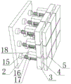
FIG. 1 is a schematic structural diagram of a clamping device for intelligent furniture production;
FIG. 2 is a schematic structural diagram of a bottom fixing tube in a clamping device for intelligent furniture production;
FIG. 3 is a schematic structural diagram of an anti-skid block used in the clamping device for intelligent furniture production;
fig. 4 is a schematic structural diagram of a fixing plate used in a clamping device for intelligent furniture production.
Wherein: 1. a material bearing plate; 2. a fixing plate; 3. an inner plate; 4. a pressure sensor; 5. an outer plate; 6. a lower plate; 7. a bottom fixed tube; 8. a circular groove; 9. a damping rod is buffered; 10. a side plate; 11. a first screw hole; 12. a first screw; 13. a limiting groove; 14. a spring; 15. a motor; 16. a threaded lead screw; 17. a nut; 18. a connecting rod; 19. a second screw hole; 21. a second screw; 22. and (4) anti-skid blocks.
Detailed Description
The technical solutions in the embodiments of the present invention will be clearly and completely described below with reference to the drawings in the embodiments of the present invention, and it is obvious that the described embodiments are only a part of the embodiments of the present invention, and not all of the embodiments. All other embodiments, which can be derived by a person skilled in the art from the embodiments given herein without making any creative effort, shall fall within the protection scope of the present invention.
In the description of the present invention, it should be noted that the terms "center", "upper", "lower", "left", "right", "vertical", "horizontal", "inner", "outer", etc., indicate orientations or positional relationships based on the orientations or positional relationships shown in the drawings, and are only for convenience of description and simplicity of description, but do not indicate or imply that the device or element being referred to must have a particular orientation, be constructed and operated in a particular orientation, and thus, should not be construed as limiting the present invention; the terms "first," "second," and "third" are used for descriptive purposes only and are not to be construed as indicating or implying relative importance, and furthermore, unless otherwise explicitly stated or limited, the terms "mounted," "connected," and "connected" are to be construed broadly and may be, for example, fixedly connected, detachably connected, or integrally connected; can be mechanically or electrically connected; they may be connected directly or indirectly through intervening media, or they may be interconnected between two elements. The specific meanings of the above terms in the present invention can be understood in specific cases to those skilled in the art.
The first embodiment is as follows:
as shown in fig. 1-4, an embodiment of the present invention provides a clamping device for intelligent furniture production, including a material supporting plate 1, fixing plates 2 are vertically and fixedly installed at two ends of the material supporting plate 1, an inner plate 3 is horizontally and slidably installed at one end of the fixing plate 2, an outer plate 5 is installed at an outer side of the inner plate 3, a pressure sensor 4 is installed between an inner end of the outer plate 5 and an outer end of the inner plate 3, the outer plate 5 is made of soft rubber, a bottom fixing pipe 7 and a buffer shock-absorbing rod 9 are installed at a lower end of the material supporting plate 1, the buffer shock-absorbing rod 9 is installed at an upper portion of the bottom fixing pipe 7, a spring 14 is installed at a position inside the bottom fixing pipe 7 and a position at a lower end of the buffer shock-absorbing rod 9, a lower plate 6 is installed at a lower side of the material supporting plate 1, a lower end of the bottom fixing pipe 7 is installed at an, the inner thread of the second screw hole 19 is connected with a second screw 21, the upper surface of the bottom fixing pipe 7 is provided with a circular groove 8, a spring 14 is arranged inside the circular groove 8, two ends of the buffering shock-absorbing rod 9 are vertically connected with side plates 10, the surface of each side plate 10 is provided with a first screw hole 11, the inner thread of each first screw hole 11 is connected with a first screw 12, two side surfaces of the bottom fixing pipe 7 are provided with limit grooves 13, the width of each limit groove 13 is larger than the diameter of each first screw 12, each first screw 12 is arranged inside each limit groove 13 in a sliding manner, a furniture material to be clamped is placed on the material bearing plate 1, the spring 14 is placed inside the circular groove 8 inside the bottom fixing pipe 7, then the buffering shock-absorbing rod 9 is placed behind the upper portion of the bottom fixing pipe 7, at the moment, the side plates 10 at two ends of the buffering shock-absorbing rod 9 are just positioned at the limit grooves 13 at two sides of the bottom fixing pipe 7, and then an operator screws the first screw 12, so that the first screw 12 can be positioned inside the limiting groove 13, at which time the buffering vibration rod 9 is limited, so that the buffer damping rod 9 can only move within a certain distance range on the upper part of the bottom fixing pipe 7 without relative movement, thereby enhancing the stability, the shock absorption effect is achieved on the material at the upper end, so that when the heavier material is suddenly placed on the material bearing plate 1, the material is prevented from being instantly crushed due to no buffer force, a very good protection effect is achieved, meanwhile, as the four springs 14 are respectively arranged at the four corners, the material at the upper end of the material supporting plate 1 is uniformly stressed and has good bearing performance, after the surface of the lower plate 6 and the second screw holes 19 at the bottom of the bottom fixing pipe 7 are aligned, the second screw 21 is rotated in, so that the lower plate 6 can be rapidly mounted at the lower ends of the four bottom fixing pipes 7.
Example two: a motor 15 is fixedly arranged at one end of the fixed plate 2, a threaded screw rod 16 is connected on an output shaft of the motor 15, a nut 17 is connected with the external thread of the threaded screw rod 16, a connecting rod 18 is fixedly connected with the upper end of the nut 17 and one end of the inner plate 3, four anti-skidding blocks 22 are arranged at the lower end of the lower plate 6, the motor 15 drives the threaded screw rod 16 to rotate, so that the rotating threaded screw rod 16 can drive the nut 17 and the connecting rod 18 at the outer end to move horizontally, meanwhile, the connecting rod 18 drives the inner plate 3 to move towards the inner side, at the moment, the inner plate 3 drives the outer plate 5 and the pressure sensor 4 between the outer plate 5 to move simultaneously, finally, the outer plate 5 can clamp the material, and meanwhile, the pressure sensor 4 carries out stress analysis, if the current force reaches a preset rated, better protection has been carried out to the material, prevents to crush the material when pressure is too big, and the planking 5 of soft rubber material can protect the surface of material simultaneously, prevents to gouge the paint layer on material surface, and the non slipping spur 22 of bottom has played skid-proof effect.
The working principle is as follows: furniture materials to be clamped are placed on the material bearing plate 1, the spring 14 is placed inside the circular groove 8 in the bottom fixing tube 7, the buffering shock absorption rod 9 is placed behind the upper portion of the bottom fixing tube 7, the side plates 10 at two ends of the buffering shock absorption rod 9 are just located at the limiting grooves 13 at two sides of the bottom fixing tube 7, the first screw 12 is screwed into the first screw hole 11 by an operator, the first screw 12 can be located inside the limiting grooves 13, the buffering shock absorption rod 9 is limited at the moment, the buffering shock absorption rod 9 can only move within a certain distance range on the upper portion of the bottom fixing tube 7, relative movement cannot occur, stability is enhanced, a shock absorption effect is achieved on the materials at the upper end, when heavy materials are suddenly placed on the material bearing plate 1, instant crushing caused by no buffer force is prevented, the protection effect is very good, meanwhile, because the four springs 14 are respectively arranged at the four corners, the material at the upper end of the material bearing plate 1 is uniformly stressed and has good bearing performance, after the surface of the lower plate 6 and the second screw holes 19 at the bottom of the bottom fixing pipes 7 are aligned, the second screw rods 21 are rotated in, the effect that the lower plate 6 is quickly installed at the lower ends of the four bottom fixing pipes 7 can be realized, the motor 15 drives the threaded screw rod 16 to rotate, the rotating threaded screw rod 16 can drive the nuts 17 and the connecting rods 18 at the outer ends to horizontally move, meanwhile, the connecting rods 18 drive the inner plate 3 to move towards the inner side, at the moment, the inner plate 3 drives the outer plate 5 and the pressure sensors 4 between the outer plate 5 to simultaneously move, finally, the outer plate 5 can clamp the material, and the pressure sensors 4 carry out stress analysis, if the current stress reaches the preset rated pressure value, at this moment, the outer plate 5 no longer moves towards the inner side, the material is no longer clamped, the material is well protected, the material is crushed when the pressure is too large, meanwhile, the outer plate 5 made of soft rubber can protect the surface of the material, the paint layer on the surface of the material is prevented from being damaged, and the anti-skid blocks 22 at the bottom play an anti-skid effect.
Although embodiments of the present invention have been shown and described, it will be appreciated by those skilled in the art that changes, modifications, substitutions and alterations can be made in these embodiments without departing from the principles and spirit of the invention, the scope of which is defined in the appended claims and their equivalents.
Claims (7)
1. The utility model provides a be used for intelligent furniture production to use clamping device which characterized in that: including material bearing board (1), the vertical fixed mounting in both ends of material bearing board (1) has fixed plate (2), the one end horizontal slip of fixed plate (2) is provided with inner panel (3), the outside of inner panel (3) is provided with planking (5), be provided with pressure sensor (4) between the outer end position of the inner of planking (5) and inner panel (3), the material of planking (5) is soft rubber, the lower extreme of material bearing board (1) is provided with the fixed pipe in bottom (7) and cushions bumper bar (9), buffering bumper bar (9) set up the upper portion of the fixed pipe in bottom (7), the inside of the fixed pipe in bottom (7) and the lower extreme position department of buffering bumper bar (9) are provided with spring (14).
2. The clamping device for intelligent furniture production according to claim 1, wherein: the lower side of the material bearing plate (1) is provided with a lower plate (6), the lower end of the bottom fixing pipe (7) is installed at the upper end position of the lower plate (6), a second screw hole (19) is formed in the surface of the lower plate (6) and the bottom surface of the bottom fixing pipe (7), and a second screw rod (21) is connected to the inner thread of the second screw hole (19).
3. The clamping device for intelligent furniture production according to claim 1, wherein: circular slot (8) have been seted up to the upper surface of bottom fixed tube (7), spring (14) set up the inside in circular slot (8).
4. The clamping device for intelligent furniture production according to claim 1, wherein: the two ends of the buffering shock absorption rod (9) are vertically connected with side plates (10), and first screw holes (11) are formed in the surfaces of the side plates (10).
5. The clamping device for intelligent furniture production according to claim 4, wherein: the internal thread of first screw (11) is connected with first screw (12), spacing groove (13) have been seted up to the both sides face of the fixed pipe in bottom (7), the width of spacing groove (13) is greater than the diameter of first screw (12), first screw (12) slide and set up in the inside of spacing groove (13).
6. The clamping device for intelligent furniture production according to claim 1, wherein: the one end fixed mounting of fixed plate (2) has motor (15), be connected with screw lead screw (16) on the output shaft of motor (15), the outside threaded connection of screw lead screw (16) has nut (17), the upper end of nut (17) and the one end fixedly connected with connecting rod (18) of inner panel (3).
7. The clamping device for intelligent furniture production according to claim 2, wherein: the lower end of the lower plate (6) is provided with four anti-skidding blocks (22).
Priority Applications (1)
| Application Number | Priority Date | Filing Date | Title |
|---|---|---|---|
| CN202110059731.3A CN112894653A (en) | 2021-01-18 | 2021-01-18 | Be used for intelligent furniture production to use clamping device |
Applications Claiming Priority (1)
| Application Number | Priority Date | Filing Date | Title |
|---|---|---|---|
| CN202110059731.3A CN112894653A (en) | 2021-01-18 | 2021-01-18 | Be used for intelligent furniture production to use clamping device |
Publications (1)
| Publication Number | Publication Date |
|---|---|
| CN112894653A true CN112894653A (en) | 2021-06-04 |
Family
ID=76114169
Family Applications (1)
| Application Number | Title | Priority Date | Filing Date |
|---|---|---|---|
| CN202110059731.3A Pending CN112894653A (en) | 2021-01-18 | 2021-01-18 | Be used for intelligent furniture production to use clamping device |
Country Status (1)
| Country | Link |
|---|---|
| CN (1) | CN112894653A (en) |
Cited By (1)
| Publication number | Priority date | Publication date | Assignee | Title |
|---|---|---|---|---|
| CN117182629A (en) * | 2023-09-20 | 2023-12-08 | 东莞市巨唯电子科技有限公司 | A CNC machine tool loading and unloading robot |
-
2021
- 2021-01-18 CN CN202110059731.3A patent/CN112894653A/en active Pending
Cited By (2)
| Publication number | Priority date | Publication date | Assignee | Title |
|---|---|---|---|---|
| CN117182629A (en) * | 2023-09-20 | 2023-12-08 | 东莞市巨唯电子科技有限公司 | A CNC machine tool loading and unloading robot |
| CN117182629B (en) * | 2023-09-20 | 2026-02-06 | 东莞市巨唯电子科技有限公司 | Feeding and discharging robot for CNC machine tool |
Similar Documents
| Publication | Publication Date | Title |
|---|---|---|
| CN114136575B (en) | New energy automobile battery anticollision detection device | |
| CN115980187A (en) | Concrete internal defect detection device and method | |
| CN218582039U (en) | Fastener for automobile maintenance | |
| CN222258650U (en) | Magnesium alloy electric vibration test bed | |
| CN215802395U (en) | Tuned damper for high-rise building quality | |
| CN215677083U (en) | Portable novel check out test set for mechanical engineering | |
| CN211189399U (en) | Spherical graphite cyclone skirt | |
| CN213633017U (en) | Mechanical impact test device for rod-shaped insulator porcelain part | |
| CN221376997U (en) | Hexagonal bolt anti-seismic testing tool | |
| CN222505391U (en) | A kind of underground pipeline deformation monitoring device | |
| CN219101953U (en) | A shock absorber for fixing electromechanical equipment | |
| CN221445374U (en) | Vibration testing machine with clamping function | |
| CN209026076U (en) | A shock absorber for an industrial computer | |
| CN208012963U (en) | A kind of steel construction resistance to compression detection device | |
| CN2172370Y (en) | Verticle lead alloy damper | |
| CN221238357U (en) | Wall crack detection device | |
| CN221725339U (en) | A protective buffer structure for a liquid level transmitter | |
| CN220830602U (en) | Cabinet installation device | |
| CN221526239U (en) | Combined electric fire detector | |
| CN219833896U (en) | Vibration motor | |
| CN220288941U (en) | Assembled bolt node anti-seismic experiment device | |
| CN212808409U (en) | Engineering vehicle motor starting current test assembly | |
| CN219292094U (en) | Bolt axial force detector | |
| CN209590224U (en) | Detect AUTOMOTIVE RELAY failed equipment | |
| CN223483287U (en) | A support device for a vibration table |
Legal Events
| Date | Code | Title | Description |
|---|---|---|---|
| PB01 | Publication | ||
| PB01 | Publication | ||
| WD01 | Invention patent application deemed withdrawn after publication |
Application publication date: 20210604 |
|
| WD01 | Invention patent application deemed withdrawn after publication |