Magnetic early warning formula fire control shower nozzle is used in wisdom fire control
Technical Field
The application relates to the field of fire control shower nozzle, especially relates to a magnetic force early warning formula fire control shower nozzle for wisdom fire control.
Background
The fire-fighting spray head is an important component in a fire-fighting spray system, and when a fire breaks out, the fire-fighting spray head sprays water so as to extinguish the fire.
The chinese patent that publication is CN112245846A discloses a magnetic force early warning formula fire control shower nozzle for wisdom fire control, which comprises a mounting base, the vertical drain pipe of having seted up that runs through on the mount pad, set up the standing groove with the drain pipe intercommunication in the mount pad, sealed sliding connection has the shutoff piece in the standing groove, the reservoir has been seted up to the mount pad lateral wall, the cell wall of reservoir has the piston board through a plurality of reset spring elastic connection, and the sealed sliding connection of the cell wall of piston board lateral wall and reservoir, the confined space that the piston board and reservoir are constituteed is the drive zone. When the conflagration breaing out, the temperature of mount pad below risees fast and reachs the curie temperature of permanent magnetism piece, then permanent magnetism piece loses magnetism gradually, thereby the magnetic field intensity that then drive area and the interior magneto rheological fluid of driven district received diminishes gradually and resumes the fluid state gradually, then piston plate resets gradually under reset spring's spring action, the interior magneto rheological fluid of driven district flows back to the drive area in through communicating pipe gradually, then the shutoff to the drain pipe is relieved gradually to the shutoff of shutoff piece, external high-pressure rivers pass through the drain pipe and impact the processing of putting out a fire to splashing on the dish.
In view of the above-mentioned related technologies, the inventor believes that after the fire sprinkler head sprays water once, the piston plate is difficult to move to the initial position under the action of the return spring, and then the magnetorheological fluid in the driving area is difficult to flow into the driven area again, so that the fire sprinkler head has a defect of being difficult to recycle.
Disclosure of Invention
In order to improve the piston board and be difficult to remove to initial position, and lead to fire control shower nozzle to be difficult to reuse's possibility, this application provides an wisdom magnetic early warning formula fire control shower nozzle for fire control.
The application provides a pair of magnetic force early warning formula fire control shower nozzle is used in wisdom fire control adopts following technical scheme to reachd:
the utility model provides a magnetic force early warning formula fire control shower nozzle for wisdom fire control, includes the mount pad, runs through in the mount pad and has seted up the drain pipe, sets up the holding tank of reservoir and reservoir intercommunication in the mount pad, holding tank and drain pipe intercommunication, sealing connection has the shutoff piece in the holding tank, and the shutoff piece is plugged up the drain pipe, and all pack in reservoir and the holding tank has magnetorheological suspensions, is equipped with the permanent magnetism piece in the mount pad, sealing connection has the piston board in the reservoir, the reservoir is close to and has set firmly compression spring between one side of holding tank and the piston board, the push rod is worn to be equipped with in one side of mount pad, the one end of push rod is worn to establish into in the reservoir to be connected with one side that the piston board deviates from compression spring, the outside of mount pad is equipped with and is used for carrying out the seal assembly with the department of wearing to establish the push rod.
Through above-mentioned technical scheme, when the conflagration breaing out, the mount pad temperature risees to the curie temperature of permanent magnetism piece rapidly, and permanent magnetism piece loses magnetism gradually for thereby magnetic field intensity that magnetorheological suspensions received diminishes gradually and resumes the fluid state gradually, then the piston plate resets gradually under compression spring's elasticity effect, and the interior magnetorheological suspensions of holding tank flows back to in the reservoir, makes the shutoff of plugging block relieving the drain pipe gradually, and external high-pressure rivers discharge through the drain pipe and put out a fire. Treat that fire is gone out the back, the operator can promote the piston board through the push rod and remove for magnetorheological suspensions in the reservoir flows to the holding tank once more, and promote the shutoff piece and remove in the holding tank, block up the drain pipe again until the shutoff piece, the mount pad temperature reduces gradually this moment, thereby make permanent magnetism piece resume magnetism gradually, magnetorheological suspensions is under strong magnetic field effect, then demonstrate high viscosity, low mobile characteristic, make the fire control shower nozzle be in again and treat the user state, the reuse of fire control shower nozzle has been realized.
Preferably: the push rod is a screw rod, the screw rod is rotationally connected with the piston plate, a connecting plate is fixedly connected to the outer side of the mounting seat, a moving block is arranged on one side, facing the screw rod, of the connecting plate, the moving block can slide along the length direction of the connecting plate, a nut is rotationally connected to one side, facing the connecting plate, of the moving block, and the nut is in threaded connection with the screw rod.
Through the technical scheme, when the piston rod needs to be pushed to move, an operator rotates the screw rod, the screw rod and the nut are in threaded rotation, the piston rod is pushed to move until the piston rod is positioned at a required position, and the operation difficulty of directly pushing the screw rod by the operator is reduced by converting the rotary movement into the linear movement; then an operator twists the nut, the nut drives the moving block to move along the length direction of the connecting plate until the nut is completely separated from the screw rod, the fixation between the nut and the screw rod is released, and the piston rod pushes the screw rod to move reversely under the action of the compression spring when a fire disaster happens.
Preferably: the moving block is provided with a through groove in a penetrating mode along the axial direction of the nut, the shape of a notch of the through groove is matched with the shape of the outer diameter of the nut, the nut is limited in the through groove in an inserting mode, one end of the nut is coaxially connected with a sleeve, one end, far away from the nut, of the sleeve is connected with a limiting piece, the outer diameter of the sleeve is smaller than the inner diameter of the through groove, and the outer diameter of the limiting piece is larger than the inner diameter of the through groove.
Through above-mentioned technical scheme, the nut has played limiting displacement to the nut with the grafting restriction that leads to the groove to the operator of being convenient for directly rotates the screw rod and just can drive the screw rod rotatory, need not to fix the nut, thereby the operation of being convenient for. Then, the operator can shift out from the through groove through moving the movable block, so that the sleeve penetrates through the through groove and is limited with the connecting block under the limiting effect of the limiting piece, and the nut is not separated from the connecting block.
Preferably: the sealing assembly comprises an end cover, the end cover is fixedly connected to the outer side of the mounting seat, the end cover is penetrated by the push rod, and a sealing ring is arranged at a through hole of the push rod on the end cover.
Through above-mentioned technical scheme, the setting of end cover and sealing washer plays double sealing's effect to the through-going hole of push rod on the mount pad, has reduced perforation department and has appeared leaking gas and cause the possibility of influence to the temperature of mount pad.
Preferably: the outside of mount pad is equipped with the protection housing, the outside at end cover and screw rod is established to the protection housing, establish to the open end towards one side of mount pad for the protection housing, the annular has been seted up towards one side of protection housing to the mount pad, the one end joint that the protection housing is close to the open end is in the annular.
Through above-mentioned technical scheme, the setting of protective housing can play the guard action to end cover and screw rod, has reduced the possibility of causing destruction to end cover and screw rod when the conflagration takes place.
Preferably: and a fireproof layer is arranged on the outer side of the protective housing.
Through the technical scheme, when a fire disaster occurs, the fireproof layer can play a role in fire prevention and flame retardance, so that the possibility that the protective housing is burnt is reduced.
Preferably: the outer side of the mounting seat is provided with a spray head below the drain pipe, and the spray head is provided with a plurality of water spray nozzles.
Through above-mentioned technical scheme, when the conflagration breaing out, when the drain pipe sprayed water towards the shower nozzle, a plurality of water jets on the shower nozzle sprayed water towards a plurality of directions to be favorable to enlarging the scope of water spray, be favorable to improving the effect of putting out a fire.
Preferably: the bottom of the mounting seat is provided with a threaded groove along the periphery of the drain pipe, the threaded groove is communicated with the drain pipe, and the spray head is in threaded connection with the inside of the threaded groove.
Through above-mentioned technical scheme, the relation of being connected can be dismantled in the adoption between shower nozzle and the screw thread recess, and the operator can be unscrewed the shower nozzle from the mount pad to the operator clears up or changes the shower nozzle, thereby the shower nozzle can normally put out a fire when making the conflagration take place.
In summary, the present application includes at least one of the following beneficial technical effects:
1. after the fire extinguishing is finished, the piston plate can be moved to the initial position again through the push rod, and when the permanent magnets recover magnetism, the position of the piston plate is fixed, so that the piston rod can be conveniently moved to the initial position, and the fire extinguishing nozzle can continuously play a fire extinguishing role when a fire disaster occurs;
2. when a fire disaster happens, the plurality of water spraying openings of the spray head spray water simultaneously, so that the water spraying area is enlarged, and the water spraying efficiency is improved.
Drawings
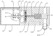
Fig. 1 is a schematic structural diagram for showing an internal structure of a mount in an embodiment of the present application.
Fig. 2 is an enlarged view of a portion a in fig. 1.
Fig. 3 is a schematic structural diagram for showing a positional relationship between a nut and a through groove on a moving block in the embodiment of the present application.
Fig. 4 is a schematic structural diagram for embodying the release of the nut and the screw in the embodiment of the present application.
Reference numerals: 1. a mounting seat; 11. a ring groove; 12. a threaded groove; 13. a spray head; 131. a water jet; 14. mounting grooves; 141. permanent magnet blocks; 2. a drain pipe; 3. a liquid storage tank; 31. magnetorheological fluid; 32. a piston plate; 33. a compression spring; 4. connecting grooves; 5. accommodating grooves; 51. a plugging block; 6. a screw; 7. a connecting plate; 71. a moving block; 711. a through groove; 72. a nut; 73. a sleeve; 74. a limiting sheet; 8. a seal assembly; 81. an end cap; 811. perforating; 812. a seal ring; 9. a protective housing; 91. and a fire-proof layer.
Detailed Description
The present application is described in further detail below with reference to figures 1-4.
The utility model discloses a magnetic force early warning formula fire control shower nozzle is used in wisdom fire control for this application embodiment.
Referring to fig. 1, magnetic early warning formula fire control shower nozzle is used in wisdom fire control, including mount pad 1, run through the drain pipe 2 of seting up and reservoir 3 and holding tank 5 of seting up along the horizontal direction of mount pad 1 along the vertical direction of mount pad 1, still be equipped with spread groove 4 between reservoir 3 and holding tank 5 in mount pad 1, through spread groove 4 intercommunication between reservoir 3 and the holding tank 5, the holding tank 5 is kept away from the one end and the drain pipe 2 intercommunication of spread groove 4. Sealing connection has the shutoff piece 51 in holding tank 5 to shutoff piece 51 slides with holding tank 5 and is connected, and shutoff piece 51 blocks up the mouth of pipe of drain pipe 2.
Referring to fig. 1, the magnetorheological fluid 31 is filled in the liquid storage tank 3, the connecting groove 4 and the accommodating tank 5, the magnetorheological fluid 31 is a suspension formed by mixing small soft magnetic particles with high magnetic conductivity and low magnetic hysteresis and non-magnetic conductive liquid, the suspension has a low-viscosity newtonian fluid characteristic under the condition of zero magnetic field, and has a high-viscosity low-fluidity characteristic under the action of a strong magnetic field, and the magnetorheological fluid 31 has a reversible rheology under the action of the magnetic field, and the shear yield strength after the rheology has a stable corresponding relationship with the magnetic field strength.
Referring to fig. 1, a piston plate 32 is hermetically connected in the reservoir 3, a compression spring 33 is arranged between one side of the reservoir 3 close to the containing tank 5 and the piston plate 32, and two ends of the compression spring 33 are respectively welded and fixed on the tank wall of the reservoir 3 and the piston plate 32. The bottom of the mounting seat 1 is provided with a mounting groove 14, a permanent magnet 141 is arranged in the mounting groove 14, and the permanent magnet 141 is welded and fixed in the mounting groove 14.
Referring to fig. 1, in an initial state, a push rod is inserted into one side of the mounting base 1, and one end of the push rod is inserted into the liquid storage tank 3 and connected to one side of the piston plate 32 away from the compression spring 33. The magnetorheological fluid 31 is changed from a liquid state to a solid state under the action of the magnetic force of the permanent magnet block 141, the magnetorheological fluid 31 does not have fluidity, the acting force on the piston plate 32 is removed, the piston plate 32 cannot be driven to reset by the compression springs 33 under the action of the magnetorheological fluid 31, the blocking block 51 is always in a blocking state on the drain pipe 2, and then the electromagnetic valve of the drain pipe 2 is opened to enable the drain pipe 2 to be in a normally open state; when a fire disaster occurs, the temperature of the mounting seat 1 is rapidly raised to the Curie temperature of the permanent magnet blocks 141, the permanent magnet blocks 141 are gradually demagnetized, the magnetic field intensity of the magnetorheological fluid 31 is gradually reduced, so that the magnetorheological fluid gradually recovers to a fluid state, the piston plate 32 is gradually reset under the elastic action of the compression spring 33, the magnetorheological fluid 31 in the accommodating groove 5 flows back to the liquid storage tank 3, the blocking block 51 is gradually removed from the drain pipe 2, and the external high-pressure water flow is discharged through the drain pipe 2 to extinguish the fire.
Referring to fig. 1, the bottom of the mounting seat 1 is provided with a threaded groove 12 below the drain pipe 2, the inner diameter of the threaded groove 12 is larger than that of the drain pipe 2, and the threaded groove 12 is communicated with the drain pipe 2. The below of drain pipe 2 is connected with shower nozzle 13, and shower nozzle 13 cooperates with 12 threaded connection of screw thread recess, is equipped with a plurality of water jets 131 on shower nozzle 13, and when shower nozzle 13 sprayed water, a plurality of water jets 131 go out water simultaneously, have enlarged the scope of putting out a fire, are favorable to improving the efficiency of putting out a fire.
Referring to fig. 2 and 3, a push rod is arranged on one side of the mounting seat 1 in a penetrating manner, the push rod is set as a screw rod 6, and one end of the screw rod 6 is arranged in the liquid storage tank 3 in a penetrating manner and is rotatably connected with one side of the piston plate 32, which is far away from the compression spring 33. The outer side of the mounting seat 1 is bonded with a connecting plate 7, the connecting plate 7 is arranged along the horizontal direction, and the connecting plate 7 is parallel to the screw 6. One side of the connecting plate 7 towards the screw 6 is provided with a moving block 71, the moving block 71 can slide along the length direction of the connecting plate 7, the moving block 71 is rotatably connected with a nut 72 towards one side of the connecting plate 7, the cross section of the nut 72 is a regular hexagon, the moving block 71 penetrates through a through groove 711 along the axial direction of the nut 72, and the shape of the notch of the through groove 711 is matched with the shape of the outer diameter of the nut 72 and is a regular hexagon. The nut 72 is inserted and limited in the through groove 711. One end of the nut 72 facing the mounting seat 1 is coaxially connected with a sleeve 73, one end of the sleeve 73 far away from the nut 72 is connected with a limiting sheet 74, the outer diameter of the sleeve 73 is smaller than the inner diameter of the through groove 711, and the outer diameter of the limiting sheet 74 is larger than the inner diameter of the through groove 711.
Referring to fig. 2 and fig. 3, after fire extinguishment is completed, when the piston plate 32 needs to be pushed to an initial position, an operator rotates the screw rod 6, the nut 72 and the movable block 71 are fixed, the screw rod 6 pushes the piston plate 32 to move towards the compression spring 33, magnetorheological fluid 31 in the liquid storage tank 3 flows into the accommodating tank 5 again, the magnetorheological fluid 31 pushes the blocking block 51 to move in the accommodating tank 5 until the blocking block 51 blocks the drain pipe 2 again, at the moment, the temperature of the mounting seat 1 is gradually reduced, magnetism of the permanent magnet block 141 is gradually restored, the magnetorheological fluid 31 presents characteristics of high viscosity and low fluidity under the action of a strong magnetic field, the fire-fighting nozzle is in a standby state, and the fire-fighting nozzle is reused.
Referring to fig. 3 and 4, the operator moves the moving block 71 toward the mounting base 1 again, so that the nut 72 is disengaged from the through groove 711, the sleeve 73 is inserted into the through groove 711, and the position of the nut 72 and the position of the moving block 71 are relatively limited by the limiting piece 74. Next, the operator turns the nut 72 so that the nut 72 moves in the axial direction of the screw 6 until the nut 72 is disengaged from the screw 6, and the nut 72 moves and simultaneously moves the moving block 71. The position of the screw 6 is limited by the release nut 72, so that the piston plate 32 pushes the screw 6 to move in the opposite direction in case of fire.
Referring to fig. 2, a sealing assembly 8 is arranged on the outer side of the mounting seat 1, the sealing assembly 8 includes an end cover 81, the end cover 81 is fixedly connected to the outer side of the mounting seat 1, a through hole 811 penetrates through the end cover 81, the screw 6 penetrates through the end cover 81 through the through hole 811, a sealing ring 812 is bonded to the inner periphery of the through hole 811, and the sealing ring 812 is attached to the screw 6. The arrangement of the end cover 81 and the sealing ring 812 is beneficial to improving the sealing effect on the mounting seat 1.
Referring to fig. 4, a protective cover shell 9 is arranged on the outer side of the mounting seat 1, the protective cover shell 9 covers the outer side of the end cover 81 and the screw 6, one side of the protective cover shell 9 facing the mounting seat 1 is set to be an open end, a ring groove 11 is formed in one side of the mounting seat 1 facing the protective cover shell 9, and one end, close to the open end, of the protective cover shell 9 is clamped in the ring groove 11. The outside of protection housing 9 scribbles one deck flame retardant coating 91, and flame retardant coating can be chooseed for use to flame retardant coating 91 and made, and flame retardant coating can improve protection housing 9's fire resistance, slows down flame spread propagation speed to improve protection housing 9's fire behavior, can play the guard action to end cover 81 and screw rod 6. When the screw 6 and the nut 72 need to be operated, the operator takes the protective housing 9 off from the outer side of the mounting seat 1, and the operation is simple and convenient.
The embodiment of the application provides a magnetic force early warning formula fire control shower nozzle for wisdom fire control's implementation principle does: when a fire disaster happens, the temperature of the mounting seat 1 is rapidly raised to the Curie temperature of the permanent magnet blocks 141, the permanent magnet blocks 141 are gradually demagnetized, the magnetic field intensity of the magnetorheological fluid 31 is gradually reduced, so that the magnetorheological fluid gradually recovers to a fluid state, the piston plate 32 is gradually reset under the elastic action of the compression spring 33, the magnetorheological fluid 31 in the accommodating groove 5 flows back to the liquid storage tank 3, the blocking block 51 is gradually removed from blocking the drain pipe 2, and the external high-pressure water flow is sprayed out through the spray head 13 connected with the drain pipe 2 to extinguish the fire. After the fire extinguishing is finished, an operator detaches the protective housing 9 from the outer side of the mounting seat 1, and then twists the screw 6, so that the screw 6 pushes the piston plate 32 to move to the initial position, and the magnetorheological fluid 31 flows into the accommodating groove 5 from the liquid storage tank 3. Until the magnetorheological fluid 31 pushes the blocking block 51 to block the drain pipe 2 again. The operator then releases the position restriction of the nut 72 and the screw 6, at which point the whole of the fire sprinkler 13 is ready for use, and then the operator again snaps the protective casing 9 into the annular groove 11.
The present embodiment is only for explaining the present application, and it is not limited to the present application, and those skilled in the art can make modifications of the present embodiment without inventive contribution as needed after reading the present specification, but all of them are protected by patent law within the scope of the claims of the present application.