CN112875303A - Tobacco leaf collecting and conveying machine - Google Patents
Tobacco leaf collecting and conveying machine Download PDFInfo
- Publication number
- CN112875303A CN112875303A CN202110058097.1A CN202110058097A CN112875303A CN 112875303 A CN112875303 A CN 112875303A CN 202110058097 A CN202110058097 A CN 202110058097A CN 112875303 A CN112875303 A CN 112875303A
- Authority
- CN
- China
- Prior art keywords
- collecting groove
- receiving
- fixed
- tobacco leaf
- brush
- Prior art date
- Legal status (The legal status is an assumption and is not a legal conclusion. Google has not performed a legal analysis and makes no representation as to the accuracy of the status listed.)
- Pending
Links
- 235000002637 Nicotiana tabacum Nutrition 0.000 title claims abstract description 45
- 244000061176 Nicotiana tabacum Species 0.000 title 1
- 239000000463 material Substances 0.000 claims abstract description 189
- 241000208125 Nicotiana Species 0.000 claims abstract description 44
- 230000005540 biological transmission Effects 0.000 claims description 16
- 238000011084 recovery Methods 0.000 claims description 10
- 238000007599 discharging Methods 0.000 claims description 3
- 230000033001 locomotion Effects 0.000 description 9
- 238000013461 design Methods 0.000 description 7
- 238000000034 method Methods 0.000 description 7
- 239000000428 dust Substances 0.000 description 5
- 230000000694 effects Effects 0.000 description 3
- 239000000843 powder Substances 0.000 description 3
- 230000001939 inductive effect Effects 0.000 description 2
- 238000012545 processing Methods 0.000 description 2
- 230000003068 static effect Effects 0.000 description 2
- 239000002699 waste material Substances 0.000 description 2
- 230000004888 barrier function Effects 0.000 description 1
- 230000009286 beneficial effect Effects 0.000 description 1
- 238000004891 communication Methods 0.000 description 1
- 238000010276 construction Methods 0.000 description 1
- 230000007547 defect Effects 0.000 description 1
- 238000009792 diffusion process Methods 0.000 description 1
- 238000012544 monitoring process Methods 0.000 description 1
Images





Classifications
-
- B—PERFORMING OPERATIONS; TRANSPORTING
- B65—CONVEYING; PACKING; STORING; HANDLING THIN OR FILAMENTARY MATERIAL
- B65G—TRANSPORT OR STORAGE DEVICES, e.g. CONVEYORS FOR LOADING OR TIPPING, SHOP CONVEYOR SYSTEMS OR PNEUMATIC TUBE CONVEYORS
- B65G53/00—Conveying materials in bulk through troughs, pipes or tubes by floating the materials or by flow of gas, liquid or foam
- B65G53/04—Conveying materials in bulk pneumatically through pipes or tubes; Air slides
- B65G53/24—Gas suction systems
-
- B—PERFORMING OPERATIONS; TRANSPORTING
- B65—CONVEYING; PACKING; STORING; HANDLING THIN OR FILAMENTARY MATERIAL
- B65G—TRANSPORT OR STORAGE DEVICES, e.g. CONVEYORS FOR LOADING OR TIPPING, SHOP CONVEYOR SYSTEMS OR PNEUMATIC TUBE CONVEYORS
- B65G37/00—Combinations of mechanical conveyors of the same kind, or of different kinds, of interest apart from their application in particular machines or use in particular manufacturing processes
-
- B—PERFORMING OPERATIONS; TRANSPORTING
- B65—CONVEYING; PACKING; STORING; HANDLING THIN OR FILAMENTARY MATERIAL
- B65G—TRANSPORT OR STORAGE DEVICES, e.g. CONVEYORS FOR LOADING OR TIPPING, SHOP CONVEYOR SYSTEMS OR PNEUMATIC TUBE CONVEYORS
- B65G53/00—Conveying materials in bulk through troughs, pipes or tubes by floating the materials or by flow of gas, liquid or foam
- B65G53/34—Details
-
- B—PERFORMING OPERATIONS; TRANSPORTING
- B65—CONVEYING; PACKING; STORING; HANDLING THIN OR FILAMENTARY MATERIAL
- B65G—TRANSPORT OR STORAGE DEVICES, e.g. CONVEYORS FOR LOADING OR TIPPING, SHOP CONVEYOR SYSTEMS OR PNEUMATIC TUBE CONVEYORS
- B65G65/00—Loading or unloading
- B65G65/30—Methods or devices for filling or emptying bunkers, hoppers, tanks, or like containers, of interest apart from their use in particular chemical or physical processes or their application in particular machines, e.g. not covered by a single other subclass
- B65G65/34—Emptying devices
- B65G65/36—Devices for emptying from the top
Landscapes
- Engineering & Computer Science (AREA)
- Mechanical Engineering (AREA)
- Manufacture Of Tobacco Products (AREA)
Abstract
The invention discloses a tobacco leaf collecting conveyor which comprises a material receiving and conveying mechanism, a material collecting groove, a material sucking mechanism and a linear moving mechanism, wherein the material collecting groove is fixed on the discharge side of the material receiving and conveying mechanism, the top opening of the material collecting groove is positioned below the material receiving and conveying mechanism, the material sucking mechanism is fixed in the material collecting groove and comprises a suction nozzle and a vacuum material sucking pipe, the bottom opening of the suction nozzle is close to the bottom in the material collecting groove, and the top of the suction nozzle is connected and communicated with the vacuum material sucking pipe; the moving direction of the linear moving mechanism is matched with the length direction of the material collecting groove, and the vacuum material sucking pipe is fixed on the linear moving mechanism. By the arrangement of the invention, the material receiving box arranged in the existing feeder can be effectively replaced, the full-automatic collection of the tobacco leaves falling from the feeder is realized, and the working efficiency is improved.
Description
Technical Field
The invention relates to a tobacco leaf collecting device, in particular to a tobacco leaf collecting conveyor, and belongs to the technical field of tobacco mechanical equipment.
Background
In the tobacco processing process, the cut tobacco is easy to fall out from corresponding processing equipment, especially from a seam of an interface of two adjacent equipment, and the fallen cut tobacco is easy to cause waste if not recovered. For example, during the feeding process of the feeder, the material is easy to leak from the bottom of the inlet end of the feeder, which cannot be effectively sealed. In the prior art, the drawer-type collecting box is arranged at the bottom of the inlet end of the feeding machine and is cleaned by workers at intervals, and the mode is very complicated and laborious.
Disclosure of Invention
Aiming at the defects in the prior art, the invention aims to provide the tobacco leaf collecting conveyor with more reasonable structural design so as to realize automatic collection and recovery.
In order to achieve the purpose, the invention adopts the technical scheme that: a tobacco leaf collecting conveyor is characterized by comprising a material receiving and conveying mechanism, a material collecting groove, a material sucking mechanism and a linear moving mechanism, wherein the material collecting groove is fixed on the discharging side of the material receiving and conveying mechanism, the top opening of the material collecting groove is positioned below the material receiving and conveying mechanism, the material sucking mechanism is fixed in the material collecting groove and comprises a suction nozzle and a vacuum material sucking pipe, the bottom opening of the suction nozzle is close to the bottom in the material collecting groove, and the top of the suction nozzle is connected with and communicated with the vacuum material sucking pipe; the moving direction of the linear moving mechanism is matched with the length direction of the material collecting groove, and the vacuum material sucking pipe is fixed on the linear moving mechanism.
Further, connect material conveying mechanism to include the frame, connect material conveyer belt, two transmission belt rollers and motor, be fixed with first brush subassembly in the one side below of the transmission belt roller that is located the material conveying mechanism discharge end, first brush subassembly includes first brush, and first brush is fixed on the outer wall of frame or collecting groove, and first brush is located collecting groove with the position that connects material conveyer belt surface to laminate mutually. The first brush component is designed to clean tobacco leaves and the like which do not fall into the material collecting groove on the surface of the material receiving conveyor belt into the material collecting groove.
Furthermore, a notch is formed on the side, close to the material receiving and conveying mechanism, of a suction nozzle of the material sucking mechanism. The design of this breach is convenient for can assist and adsorb the material receiving conveyer belt surface tobacco leaf, the dust that convey to the groove side of gathering materials simultaneously when carrying out the material with tobacco leaf in the groove of gathering materials.
Furthermore, the vacuum material suction pipe of the material suction mechanism comprises a cylindrical body, the bottom of the cylindrical body is connected and communicated with a suction nozzle, the top of the cylindrical body is fixedly connected and communicated with a recovery hose, an annular air duct is formed in the wall of the cylindrical body, correspondingly, an air outlet communicated with the annular air duct and the inner cavity of the cylindrical body is formed in the inner side of the inner wall of the cylindrical body, the air outlet is formed in a shape of inclining upwards from the side of the annular air duct to the side of the inner cavity of the cylindrical body, and an air supply pipe communicated with the annular air duct is fixedly connected to the outer wall of the cylindrical body. With the design of vacuum material suction pipe, can save the disposition of rotating parts such as vacuum pump, negative pressure generator, practiced thrift the cost, more importantly simultaneously, the tobacco leaf can directly be carried from vacuum material suction pipe, does not pass through any rotation piece, can effectively avoid midway adhesion or the card of pipe tobacco to go into.
Furthermore, a ripple cover is arranged at the opening at the top of the material collecting groove and fixed on the two sides of the vacuum material sucking pipe and the two sides of the material collecting groove in the length direction. The arrangement that the ripple was covered can reduce the probability that the dust that produces in the collecting trough outwards environment diffusion.
Furthermore, a second brush assembly and a third brush assembly are fixed on the side of the feeding end of the material receiving conveying belt of the material receiving conveying mechanism, a second brush of the second brush assembly extends downwards and is attached to the upper surface of the material receiving conveying belt, and a third brush of the third brush assembly extends upwards and is attached to the inner surface of the material receiving conveying belt. This design can be connecing the static when connecing the material of connecing the material conveyer belt, and to falling to connect the material of material conveyer belt to play the barrier effect.
Furthermore, a roller is respectively fixed at the bottom of the rack of the material receiving and conveying mechanism and at the position close to four corners, wherein at least two rollers are rollers with brakes.
Furthermore, the length of the material collecting groove is larger than or equal to the width of the material receiving transmission belt, and the span of the suction nozzle in the width direction of the material collecting groove is adapted to the width of the material collecting groove.
Compared with the prior art, the invention has the beneficial effects that:
(1) by the arrangement of the invention, a receiving box arranged in the existing feeder can be effectively replaced, so that the tobacco leaves falling from the feeder can be fully automatically collected, and the working efficiency is improved;
(2) through the arrangement of the vacuum material sucking mechanism and the like, the tobacco leaves falling into the material collecting groove can be effectively collected, the material sucking is relatively more sufficient, and the waste of the tobacco leaves is effectively avoided;
(3) the material leakage collecting device is quite reasonable in structural design, not only can be suitable for material leakage collection of the feeding machine, but also can be suitable for other equipment which is easy to leak materials, particularly equipment with more material leakage points;
(4) the invention can collect the complete tobacco leaves, and can also recover the tobacco shreds, the tobacco powder and the like, so that the tobacco shreds, the tobacco powder and the like can be completely recovered.
Drawings
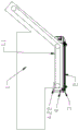
FIG. 1 is a schematic view of the three-dimensional structure of the present invention installed in a feeder,
figure 2 is a front view of the present invention installed in a feeder,
figure 3 is a schematic perspective view of the present invention,
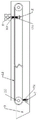
FIG. 4 is a schematic perspective view of the combination of the material collecting tank and the material sucking mechanism,
FIG. 5 is a schematic view showing the state of the first brush assembly, the second brush assembly, the third brush assembly and the material receiving and conveying mechanism according to the present invention,
figure 6 is a schematic perspective view of the material suction mechanism of the present invention,
FIG. 7 is a structural cross-sectional view of a vacuum material sucking pipe of the material sucking mechanism according to the present invention,
FIG. 8 is a front view of a suction nozzle of the suction mechanism of the present invention;
the device comprises a feeding machine 1, a feeding machine 1.1, a feeding machine conveying belt horizontal section 2, a material receiving conveying mechanism 2.1, a rack 2.2, a material receiving conveying belt 2.3, a transmission belt roller 3, a material collecting groove 4, a material sucking mechanism 4.1, a suction nozzle 4.11, a notch 4.2, a vacuum material sucking pipe 4.21, a cylindrical body 4.22, a recovery hose 4.23, an annular air duct 4.24, an air port 4.3, a mounting seat 5, a linear moving mechanism 6, an air feeding pipe 7, a first brush assembly 7.1, a first brush 8, a ripple cover 9, a roller 10, a drag chain 11, a second brush assembly 11.1, a second brush 12, a third brush assembly 12.1, a third brush 13 and an electrical control cabinet.
Detailed Description
In order to make the technical solutions better understood by those skilled in the art, the technical solutions in the embodiments of the present application will be clearly and completely described below with reference to the drawings in the embodiments of the present application, and it is obvious that the described embodiments are only partial embodiments of the present application, but not all embodiments. All other embodiments, which can be derived by a person skilled in the art from the embodiments given herein without making any creative effort, shall fall within the protection scope of the present application.
It should be noted that the terms "first," "second," and the like in the description and claims of this application and in the drawings described above are used for distinguishing between similar elements and not necessarily for describing a particular sequential or chronological order. It should be understood that the data so used may be interchanged under appropriate circumstances such that embodiments of the application described herein may be used. Furthermore, the terms "comprises," "comprising," and "having," and any variations thereof, are intended to cover a non-exclusive inclusion, such that a process, method, system, article, or apparatus that comprises a list of steps or elements is not necessarily limited to those steps or elements expressly listed, but may include other steps or elements not expressly listed or inherent to such process, method, article, or apparatus.
In this application, the terms "upper", "lower", "left", "right", "front", "rear", "top", "bottom", "inner", "outer", "middle", "vertical", "horizontal", "lateral", "longitudinal", and the like indicate orientations or positional relationships based on the orientations or positional relationships shown in the drawings. These terms are used primarily to better describe the present application and its embodiments, and are not used to limit the indicated devices, elements or components to a particular orientation or to be constructed and operated in a particular orientation.
Moreover, some of the above terms may be used to indicate other meanings besides the orientation or positional relationship, for example, the term "on" may also be used to indicate some kind of attachment or connection relationship in some cases. The specific meaning of these terms in this application will be understood by those of ordinary skill in the art as appropriate.
Furthermore, the terms "mounted," "disposed," "provided," "connected," and "sleeved" are to be construed broadly. For example, it may be a fixed connection, a removable connection, or a unitary construction; can be a mechanical connection, or an electrical connection; may be directly connected, or indirectly connected through intervening media, or may be in internal communication between two devices, elements or components. The specific meaning of the above terms in the present application can be understood by those of ordinary skill in the art as appropriate.
It should be noted that the embodiments and features of the embodiments in the present application may be combined with each other without conflict. The present application will be described in detail below with reference to the embodiments with reference to the attached drawings.
As shown in fig. 1-8, the tobacco leaf collecting conveyor of the present invention comprises a material receiving and conveying mechanism 2, a material collecting groove 3, a material sucking mechanism 4, and a linear moving mechanism 5. Wherein connect material conveying mechanism 2 to set up under feeder conveyor belt horizontal segment 1.1 of feeder 1, and connect material conveying mechanism 2 to include frame 2.1, connect material conveyer belt 2.2, two transmission belt rollers 2.3 and motor, wherein connect the length of material conveyer belt 2.2 to be greater than the length of feeder conveyor belt horizontal segment 1.1, two transmission belt rollers 2.3 (be transmission initiative belt roller and transmission passive belt roller) are fixed on frame 2.1 according to conventional mode, connect material conveyer belt 2.2 to form an annular conveyer belt for the conveyer belt of level setting and after passing around from two transmission belt rollers 2.3, motor drive transmission initiative belt roller. A material collecting groove 3 is fixed at the discharging side of a material receiving and conveying mechanism 2 (specifically a material receiving and conveying belt 2.2), the material collecting groove 3 is specifically fixed on a frame 2.1, the top opening of the material collecting groove 3 is positioned below the material receiving and conveying mechanism 2 (specifically the material receiving and conveying belt 2.2), a material sucking mechanism 4 is fixed in the material collecting groove 3, the material sucking mechanism 4 comprises a suction nozzle 4.1 and a vacuum material sucking pipe 4.2, wherein the bottom opening of the suction nozzle 4 is close to the inner bottom of the material collecting groove 3, the width of the bottom opening of the suction nozzle 4 is matched with the width of the inner bottom of the material collecting groove 3, the top of the suction nozzle 4 is connected and communicated with the vacuum material sucking pipe 4.2, the top of the vacuum material sucking pipe 4.2 is fixedly connected and communicated with a recovery hose 4.22, the other end of the recovery hose 4.22 is arranged above the horizontal section 1.1 of the conveying belt of the feeding machine, tobacco leaves, cut tobaccos and other materials falling from the feeding machine are received by the material, the material is absorbed and returned to the horizontal section 1.1 of the conveyor belt of the feeder through the material absorbing mechanism 4 in the material collecting groove 3, so that the purpose of recovery is realized. The moving direction of the linear moving mechanism 5 is matched with the length direction of the material collecting groove 3, the vacuum suction pipe 4.2 is fixed on the linear moving mechanism 5 through the L-shaped mounting seat 4.3, and the linear moving mechanism 5 drives the vacuum suction pipe 4.2 and the suction nozzle 4.1 to reciprocate in the material collecting groove 3 to perform linear motion, so that the suction of materials such as tobacco leaves and the like collected in the material collecting groove 3 is realized, and the materials are recovered into the feeding machine 1.
The linear moving mechanism 5 is fixed on the frame 2.1 through a portal frame, and the linear moving mechanism 5 can be any mechanism capable of realizing linear reciprocating motion in the prior art, such as a gear rack sliding table module, a thread transmission sliding table module, a crank block mechanism, a hydraulic cylinder, an air cylinder and the like.
The invention also fixes a first brush component 7 under one side of the transmission belt roller 2.3 at the discharge end of the material receiving and conveying mechanism 2, the first brush component 7 comprises a first brush 7.1, the first brush 7.1 is fixedly connected on the outer wall of the frame 2.1 or the material collecting groove 3, and the position where the first brush 7.1 is jointed with the surface of the material receiving and conveying belt 2.2 is positioned in the material collecting groove 3. The first brush component is designed to clean tobacco dust and the like which do not fall into the material collecting groove 3 on the surface of the material receiving conveying belt 2.2 into the material collecting groove 3.
According to the invention, a notch 4.11 is formed on the side, close to the material receiving and conveying mechanism 2, of the suction nozzle 4.1 of the material absorbing mechanism 4, the upper edge of the notch 4.11 is designed to be slightly higher than the upper surface of the material receiving and conveying belt 2.2, and the shape of the notch 4.11 can be rectangular, trapezoidal, semicircular, circular and the like. The design of this breach 4.11 is convenient for can assist and adsorb the material receiving conveyer belt 2.2 surface tobacco leaf, the dust that convey to the 3 sides of groove 3 that gathers materials simultaneously when inhaling the material with the tobacco leaf in the groove 3 that gathers materials.
The vacuum material suction pipe 4.2 comprises a cylindrical body 4.21, wherein the bottom of the cylindrical body 4.21 is fixedly connected and communicated with a suction nozzle 4.1, the top of the cylindrical body 4.21 is fixedly connected and communicated with a recovery hose 4.22, an annular air duct 4.23 is arranged inside the wall of the cylindrical body 4.21, correspondingly, an air outlet 4.24 for communicating the annular air duct 4.23 with the inner cavity of the cylindrical body 4.21 is arranged on the inner side of the inner wall of the cylindrical body 4.21, the air outlet 4.24 is obliquely (upwards obliquely) arranged from the annular air duct 4.23 side to the inner cavity side of the cylindrical body 4.21, and an air supply pipe 6 communicated with the annular air duct 4.23 is fixedly connected on the outer wall of the cylindrical body 4.21. The air is actively supplied through the air supply pipe 6, the air flow is blown out upwards from the air outlet 4.24 which is inclined upwards through the annular air duct 4.23, the air flow at the original air outlet in the tubular body 4.21 is driven to flow upwards, the flow velocity of the air flow at the part is accelerated, according to the Bernoulli principle, the air pressure at the part is reduced, and the parts such as the suction nozzle 4.1 and the material collecting groove 3 are communicated with the external environment and belong to the atmospheric pressure, so that a certain air pressure difference is formed between the material collecting groove 3 and the top of the vacuum material suction pipe, and the materials in the material collecting groove are collected and conveyed. The vacuum material sucking pipe 4.2 is designed in such a way, so that the arrangement of rotating parts such as a vacuum pump, a negative pressure generator and the like can be omitted, the cost is saved, and more importantly, the tobacco leaves can be directly conveyed from the vacuum material sucking pipe 4.2 of the cylindrical body without passing through any rotating part, and the midway adhesion or clamping of the cut tobacco can be effectively avoided.
The invention also arranges a ripple cover 8 made of flexible material (such as rubber material) at the opening of the top of the collecting groove 3, and the ripple cover 8 is fixed at both sides of the vacuum material sucking pipe 4.2 and both sides of the collecting groove 3 in the length direction. The arrangement of the ripple cover 8 can reduce the probability that dust generated in the collecting groove 3 is diffused to the external environment.
Meanwhile, a second brush assembly 11 and a third brush assembly 12 are respectively fixed on the feeding end side of the material receiving conveying belt 2.2 of the material receiving conveying mechanism 2, a second brush 11.1 of the second brush assembly 11 extends downwards and is attached to the upper surface of the material receiving conveying belt 2.2, and a third brush 12.1 of the third brush assembly 12 extends upwards and is attached to the inner surface of the material receiving conveying belt 2. This design can be when connecing the static material of connecing of material conveyer belt 2.2 to connect, plays the effect of blockking to the material that falls to connect material conveyer belt 2.2.
In addition, the invention is fixed with a roller 9 at the bottom of the frame 2.1 of the material receiving and conveying mechanism 2 and near the four corners, wherein at least two rollers 9 are rollers with brake.
The length of the collecting groove 3 is larger than or equal to the width of the material receiving transmission belt 2.2, and the span of the suction nozzle 4.1 in the width direction of the collecting groove 3 is adapted to the width of the collecting groove 3. And the pipeline (air supply pipe) of the material suction mechanism is fixed in the drag chain 10, the drag chain 10 is fixed on the frame 2.1 according to the conventional mode, and the motion direction of the drag chain 10 is parallel to the motion direction of the linear motion mechanism 5.
The invention is started once when the feeder 1 starts to be started, and then the intermittent start is carried out in the working process of the feeder 1. In practice, one side at feeder 1 conveyor belt roller sets up position inductive switch, respectively set up a position inductive switch at linear motion mechanism's both ends, when monitoring that feeder conveyor belt begins to operate, connect material conveyer belt 2.2, linear motion mechanism 5 and inhale material mechanism 4 and all begin to start once, linear motion mechanism 5 drives and inhales material mechanism 4 and at least toward or return once in setting up and starting once, then in the course of operation of feeder 1, set up the clearance formula and start, if according to the material leakage condition of reality, set up and start the interval time. The materials including tobacco leaves leaked from the feeding machine 1 fall on the material receiving conveyor belt 2.2, the material receiving conveyor belt 2.2 conveys the materials on the material receiving conveyor belt to the material collecting groove 3, and the reciprocating movement of the material sucking mechanism 4 realizes the collection of the materials in the material collecting groove 3 and the recovery of the materials to the horizontal section 1.1 of the conveying belt of the feeding machine 1.
The invention can also be used in other tobacco conveying equipment except the feeding machine, can realize full-automatic material recovery, can recover the materials relatively cleanly, can recover the materials together with tobacco powder, and has very good effect.
Claims (8)
1. A tobacco leaf collecting conveyor is characterized by comprising a material receiving and conveying mechanism, a material collecting groove, a material sucking mechanism and a linear moving mechanism, wherein the material collecting groove is fixed on the discharging side of the material receiving and conveying mechanism, the top opening of the material collecting groove is positioned below the material receiving and conveying mechanism, the material sucking mechanism is fixed in the material collecting groove and comprises a suction nozzle and a vacuum material sucking pipe, the bottom opening of the suction nozzle is close to the bottom in the material collecting groove, and the top of the suction nozzle is connected with and communicated with the vacuum material sucking pipe; the moving direction of the linear moving mechanism is matched with the length direction of the material collecting groove, and the vacuum material sucking pipe is fixed on the linear moving mechanism.
2. The tobacco leaf collecting and conveying machine according to claim 1, wherein the material receiving and conveying mechanism comprises a frame, a material receiving conveying belt, two transmission belt rollers and a motor, a first brush assembly is fixed below one side of the transmission belt roller at the discharge end of the material receiving and conveying mechanism, the first brush assembly comprises a first brush, the first brush is fixed on the outer wall of the frame or a material collecting groove, and the part, attached to the surface of the material receiving conveying belt, of the first brush is located in the material collecting groove.
3. The tobacco leaf collecting and conveying machine according to claim 1, wherein the suction nozzle of the suction mechanism is notched at a side close to the receiving and conveying mechanism.
4. The tobacco leaf collecting and conveying machine according to claim 1, 2 or 3, wherein the vacuum material sucking pipe of the material sucking mechanism comprises a cylindrical body, the bottom of the cylindrical body is connected and communicated with the suction nozzle, the top of the cylindrical body is fixedly connected and communicated with the recovery hose, an annular air duct is formed in the wall of the cylindrical body, correspondingly, an air outlet for communicating the annular air duct with the inner cavity of the cylindrical body is formed in the inner side of the inner wall of the cylindrical body, the air outlet is formed in a shape inclined upwards from the annular air duct side to the inner cavity side of the cylindrical body, and an air feeding pipe communicated with the annular air duct is fixedly connected to the outer wall of the cylindrical body.
5. The tobacco leaf collecting conveyor according to claim 4, wherein a ripple cover is provided at the top opening of the catch tank, and the ripple cover is fixed to both sides of the vacuum suction pipe and both sides of the catch tank in the length direction.
6. The tobacco leaf collecting conveyor according to claim 5, wherein a second brush assembly and a third brush assembly are fixed on the feeding end side of the receiving conveyor belt of the receiving conveyor mechanism, a second brush of the second brush assembly extends downwards and is attached to the upper surface of the receiving conveyor belt, and a third brush of the third brush assembly extends upwards and is attached to the inner surface of the receiving conveyor belt.
7. The tobacco leaf collecting conveyor according to claim 1, wherein a roller is fixed at the bottom of the frame of the receiving and conveying mechanism and near each of the four corners, and at least two of the rollers are belt brake rollers.
8. The tobacco leaf collecting conveyor according to claim 1, wherein the length of the collecting trough is greater than or equal to the width of the collecting transmission belt, and the span of the suction nozzle in the width direction of the collecting trough is adapted to the width of the collecting trough.
Priority Applications (1)
| Application Number | Priority Date | Filing Date | Title |
|---|---|---|---|
| CN202110058097.1A CN112875303A (en) | 2021-01-16 | 2021-01-16 | Tobacco leaf collecting and conveying machine |
Applications Claiming Priority (1)
| Application Number | Priority Date | Filing Date | Title |
|---|---|---|---|
| CN202110058097.1A CN112875303A (en) | 2021-01-16 | 2021-01-16 | Tobacco leaf collecting and conveying machine |
Publications (1)
| Publication Number | Publication Date |
|---|---|
| CN112875303A true CN112875303A (en) | 2021-06-01 |
Family
ID=76048520
Family Applications (1)
| Application Number | Title | Priority Date | Filing Date |
|---|---|---|---|
| CN202110058097.1A Pending CN112875303A (en) | 2021-01-16 | 2021-01-16 | Tobacco leaf collecting and conveying machine |
Country Status (1)
| Country | Link |
|---|---|
| CN (1) | CN112875303A (en) |
Cited By (1)
| Publication number | Priority date | Publication date | Assignee | Title |
|---|---|---|---|---|
| CN117923200A (en) * | 2024-02-05 | 2024-04-26 | 浙江中烟工业有限责任公司 | Dust removing and recycling device of feeding machine |
Citations (11)
| Publication number | Priority date | Publication date | Assignee | Title |
|---|---|---|---|---|
| GB1186802A (en) * | 1967-03-06 | 1970-04-08 | American Mach & Foundry | Cut Tobacco Stemmer |
| CN2920924Y (en) * | 2006-04-19 | 2007-07-11 | 许宪铭 | Improved structure of air feeder |
| CN201938340U (en) * | 2010-12-01 | 2011-08-24 | 昆明烟机集团二机有限公司 | Movable cleaning device for top band of tobacco cutter |
| CN203486514U (en) * | 2013-09-27 | 2014-03-19 | 张家口市东力机械制造有限责任公司 | Leaked tobacco shred recycling device of tobacco shred feeding machine |
| CN105621104A (en) * | 2016-01-26 | 2016-06-01 | 益阳胜希机械设备制造有限公司 | Tea leaf suction type pneumatic conveying suction nozzle |
| CN207107758U (en) * | 2017-07-24 | 2018-03-16 | 平湖市开元混凝土有限公司 | A kind of clearing and retrieving device of conveyer belt |
| CN108236128A (en) * | 2018-01-29 | 2018-07-03 | 张佳奇 | A kind of anti-tossed device of the feeding of cigarette machine |
| CN209684690U (en) * | 2019-01-04 | 2019-11-26 | 广西中烟工业有限责任公司 | A storage-type cigarette feeder material leftover online cleaning and recycling device |
| CN110712965A (en) * | 2019-10-18 | 2020-01-21 | 河南中烟工业有限责任公司 | A belt conveyor leaking foam recovery device |
| CN210594358U (en) * | 2019-06-27 | 2020-05-22 | 武汉海博机电工程有限公司 | Automatic ash collecting and environment-friendly system for ship loader head |
| CN215287068U (en) * | 2021-01-16 | 2021-12-24 | 常德市锦桓机电有限责任公司 | Tobacco leaf collecting, receiving and recycling mechanism |
-
2021
- 2021-01-16 CN CN202110058097.1A patent/CN112875303A/en active Pending
Patent Citations (11)
| Publication number | Priority date | Publication date | Assignee | Title |
|---|---|---|---|---|
| GB1186802A (en) * | 1967-03-06 | 1970-04-08 | American Mach & Foundry | Cut Tobacco Stemmer |
| CN2920924Y (en) * | 2006-04-19 | 2007-07-11 | 许宪铭 | Improved structure of air feeder |
| CN201938340U (en) * | 2010-12-01 | 2011-08-24 | 昆明烟机集团二机有限公司 | Movable cleaning device for top band of tobacco cutter |
| CN203486514U (en) * | 2013-09-27 | 2014-03-19 | 张家口市东力机械制造有限责任公司 | Leaked tobacco shred recycling device of tobacco shred feeding machine |
| CN105621104A (en) * | 2016-01-26 | 2016-06-01 | 益阳胜希机械设备制造有限公司 | Tea leaf suction type pneumatic conveying suction nozzle |
| CN207107758U (en) * | 2017-07-24 | 2018-03-16 | 平湖市开元混凝土有限公司 | A kind of clearing and retrieving device of conveyer belt |
| CN108236128A (en) * | 2018-01-29 | 2018-07-03 | 张佳奇 | A kind of anti-tossed device of the feeding of cigarette machine |
| CN209684690U (en) * | 2019-01-04 | 2019-11-26 | 广西中烟工业有限责任公司 | A storage-type cigarette feeder material leftover online cleaning and recycling device |
| CN210594358U (en) * | 2019-06-27 | 2020-05-22 | 武汉海博机电工程有限公司 | Automatic ash collecting and environment-friendly system for ship loader head |
| CN110712965A (en) * | 2019-10-18 | 2020-01-21 | 河南中烟工业有限责任公司 | A belt conveyor leaking foam recovery device |
| CN215287068U (en) * | 2021-01-16 | 2021-12-24 | 常德市锦桓机电有限责任公司 | Tobacco leaf collecting, receiving and recycling mechanism |
Cited By (1)
| Publication number | Priority date | Publication date | Assignee | Title |
|---|---|---|---|---|
| CN117923200A (en) * | 2024-02-05 | 2024-04-26 | 浙江中烟工业有限责任公司 | Dust removing and recycling device of feeding machine |
Similar Documents
| Publication | Publication Date | Title |
|---|---|---|
| CN118545468B (en) | An automatic cleaning material conveyor for refractory production | |
| CN111112167A (en) | PCB board ash removal processing apparatus | |
| CN215287068U (en) | Tobacco leaf collecting, receiving and recycling mechanism | |
| CN115666120B (en) | A feeding mechanism for a high-speed SMT placement machine | |
| CN108858537A (en) | Timber cutting equipment filing collector | |
| CN209536465U (en) | A kind of suspension type dring yard cereal collects machine | |
| CN216511647U (en) | Grain conveyor with dust removal function | |
| CN206325314U (en) | Deduster | |
| CN222094112U (en) | Plastic part surface laminating machine | |
| CN109109455A (en) | A kind of dust-extraction unit of printing machine | |
| CN216037026U (en) | Sealing device capable of absorbing material dust | |
| CN220264207U (en) | Belt conveyor with cleaning mechanism | |
| CN216937251U (en) | Paster surface cleaning device for high-speed paster machine | |
| CN207230787U (en) | A kind of air-conditioning filter screen | |
| CN213201617U (en) | Corridor dust removal device | |
| CN218797833U (en) | Gluing equipment for honeycomb paperboard | |
| CN212733383U (en) | Semi-automatic rubber box dust remover | |
| CN211802767U (en) | Automatic scrap removing production line for parts | |
| CN222885740U (en) | Cleaning and dust removing device of plastic suction packaging box cutting machine | |
| CN216917859U (en) | Belt feeder seal conveying system | |
| CN223226238U (en) | Cashmere carding machine capable of removing goat skin dander | |
| CN216095296U (en) | Automatic PCBA dust collector | |
| CN217534382U (en) | Environment-friendly wear-resistant conveying belt for tobacco production | |
| CN218372637U (en) | Wool feeder dust removal mechanism for wool washing production line | |
| CN215918298U (en) | Flexible line way board production line dust collector |
Legal Events
| Date | Code | Title | Description |
|---|---|---|---|
| PB01 | Publication | ||
| PB01 | Publication | ||
| SE01 | Entry into force of request for substantive examination | ||
| SE01 | Entry into force of request for substantive examination | ||
| RJ01 | Rejection of invention patent application after publication |
Application publication date: 20210601 |
|
| RJ01 | Rejection of invention patent application after publication |