CN112872836A - Continuous perforating device of steel construction for building - Google Patents
Continuous perforating device of steel construction for building Download PDFInfo
- Publication number
- CN112872836A CN112872836A CN202110426338.3A CN202110426338A CN112872836A CN 112872836 A CN112872836 A CN 112872836A CN 202110426338 A CN202110426338 A CN 202110426338A CN 112872836 A CN112872836 A CN 112872836A
- Authority
- CN
- China
- Prior art keywords
- wall
- sliding
- frame
- fixed
- perforating
- Prior art date
- Legal status (The legal status is an assumption and is not a legal conclusion. Google has not performed a legal analysis and makes no representation as to the accuracy of the status listed.)
- Withdrawn
Links
Images


Classifications
-
- B—PERFORMING OPERATIONS; TRANSPORTING
- B23—MACHINE TOOLS; METAL-WORKING NOT OTHERWISE PROVIDED FOR
- B23Q—DETAILS, COMPONENTS, OR ACCESSORIES FOR MACHINE TOOLS, e.g. ARRANGEMENTS FOR COPYING OR CONTROLLING; MACHINE TOOLS IN GENERAL CHARACTERISED BY THE CONSTRUCTION OF PARTICULAR DETAILS OR COMPONENTS; COMBINATIONS OR ASSOCIATIONS OF METAL-WORKING MACHINES, NOT DIRECTED TO A PARTICULAR RESULT
- B23Q1/00—Members which are comprised in the general build-up of a form of machine, particularly relatively large fixed members
- B23Q1/25—Movable or adjustable work or tool supports
- B23Q1/26—Movable or adjustable work or tool supports characterised by constructional features relating to the co-operation of relatively movable members; Means for preventing relative movement of such members
-
- B—PERFORMING OPERATIONS; TRANSPORTING
- B23—MACHINE TOOLS; METAL-WORKING NOT OTHERWISE PROVIDED FOR
- B23B—TURNING; BORING
- B23B39/00—General-purpose boring or drilling machines or devices; Sets of boring and/or drilling machines
- B23B39/14—General-purpose boring or drilling machines or devices; Sets of boring and/or drilling machines with special provision to enable the machine or the drilling or boring head to be moved into any desired position, e.g. with respect to immovable work
-
- B—PERFORMING OPERATIONS; TRANSPORTING
- B23—MACHINE TOOLS; METAL-WORKING NOT OTHERWISE PROVIDED FOR
- B23Q—DETAILS, COMPONENTS, OR ACCESSORIES FOR MACHINE TOOLS, e.g. ARRANGEMENTS FOR COPYING OR CONTROLLING; MACHINE TOOLS IN GENERAL CHARACTERISED BY THE CONSTRUCTION OF PARTICULAR DETAILS OR COMPONENTS; COMBINATIONS OR ASSOCIATIONS OF METAL-WORKING MACHINES, NOT DIRECTED TO A PARTICULAR RESULT
- B23Q11/00—Accessories fitted to machine tools for keeping tools or parts of the machine in good working condition or for cooling work; Safety devices specially combined with or arranged in, or specially adapted for use in connection with, machine tools
- B23Q11/0032—Arrangements for preventing or isolating vibrations in parts of the machine
-
- B—PERFORMING OPERATIONS; TRANSPORTING
- B23—MACHINE TOOLS; METAL-WORKING NOT OTHERWISE PROVIDED FOR
- B23Q—DETAILS, COMPONENTS, OR ACCESSORIES FOR MACHINE TOOLS, e.g. ARRANGEMENTS FOR COPYING OR CONTROLLING; MACHINE TOOLS IN GENERAL CHARACTERISED BY THE CONSTRUCTION OF PARTICULAR DETAILS OR COMPONENTS; COMBINATIONS OR ASSOCIATIONS OF METAL-WORKING MACHINES, NOT DIRECTED TO A PARTICULAR RESULT
- B23Q11/00—Accessories fitted to machine tools for keeping tools or parts of the machine in good working condition or for cooling work; Safety devices specially combined with or arranged in, or specially adapted for use in connection with, machine tools
- B23Q11/0042—Devices for removing chips
- B23Q11/005—Devices for removing chips by blowing
-
- B—PERFORMING OPERATIONS; TRANSPORTING
- B23—MACHINE TOOLS; METAL-WORKING NOT OTHERWISE PROVIDED FOR
- B23Q—DETAILS, COMPONENTS, OR ACCESSORIES FOR MACHINE TOOLS, e.g. ARRANGEMENTS FOR COPYING OR CONTROLLING; MACHINE TOOLS IN GENERAL CHARACTERISED BY THE CONSTRUCTION OF PARTICULAR DETAILS OR COMPONENTS; COMBINATIONS OR ASSOCIATIONS OF METAL-WORKING MACHINES, NOT DIRECTED TO A PARTICULAR RESULT
- B23Q3/00—Devices holding, supporting, or positioning work or tools, of a kind normally removable from the machine
- B23Q3/02—Devices holding, supporting, or positioning work or tools, of a kind normally removable from the machine for mounting on a work-table, tool-slide, or analogous part
- B23Q3/06—Work-clamping means
-
- B—PERFORMING OPERATIONS; TRANSPORTING
- B23—MACHINE TOOLS; METAL-WORKING NOT OTHERWISE PROVIDED FOR
- B23Q—DETAILS, COMPONENTS, OR ACCESSORIES FOR MACHINE TOOLS, e.g. ARRANGEMENTS FOR COPYING OR CONTROLLING; MACHINE TOOLS IN GENERAL CHARACTERISED BY THE CONSTRUCTION OF PARTICULAR DETAILS OR COMPONENTS; COMBINATIONS OR ASSOCIATIONS OF METAL-WORKING MACHINES, NOT DIRECTED TO A PARTICULAR RESULT
- B23Q3/00—Devices holding, supporting, or positioning work or tools, of a kind normally removable from the machine
- B23Q3/02—Devices holding, supporting, or positioning work or tools, of a kind normally removable from the machine for mounting on a work-table, tool-slide, or analogous part
- B23Q3/10—Auxiliary devices, e.g. bolsters, extension members
- B23Q3/103—Constructional elements used for constructing work holders
-
- B—PERFORMING OPERATIONS; TRANSPORTING
- B23—MACHINE TOOLS; METAL-WORKING NOT OTHERWISE PROVIDED FOR
- B23Q—DETAILS, COMPONENTS, OR ACCESSORIES FOR MACHINE TOOLS, e.g. ARRANGEMENTS FOR COPYING OR CONTROLLING; MACHINE TOOLS IN GENERAL CHARACTERISED BY THE CONSTRUCTION OF PARTICULAR DETAILS OR COMPONENTS; COMBINATIONS OR ASSOCIATIONS OF METAL-WORKING MACHINES, NOT DIRECTED TO A PARTICULAR RESULT
- B23Q2703/00—Work clamping
- B23Q2703/12—Accessories for attaching
Abstract
The invention discloses a continuous punching device for a steel structure for a building, and relates to the technical field of building equipment; in order to solve the problem that the angle of the drill bit cannot be changed; the electric sliding rail device comprises an outer shell, wherein support frames are fixed on two sides of the inner wall of the bottom of the outer shell respectively through hydraulic rods, a fixing mechanism is arranged on the outer wall of the top of each support frame, a first circular electric sliding rail and a second circular electric sliding rail are fixed on the inner wall of two sides of the outer shell respectively through a first fixing support and a second fixing support, and sliding blocks are respectively connected to the inner walls of one side of the first circular electric sliding rail and the inner wall of one. The punching head comprises a circular electric sliding rail I, a circular electric sliding rail II, a punching frame, a fixing mechanism, a sliding block, a hydraulic rod, a sliding block, a punching head and a punching head.
Description
Technical Field
The invention relates to the technical field of building equipment, in particular to a continuous punching device for a steel structure for a building.
Background
The steel structure is a structure composed of steel materials and is one of the main building structure types; in the production and processing processes of the steel structure, punching treatment needs to be carried out on the steel structure, so that a continuous punching device for the steel structure for the building is needed.
Through the retrieval, chinese patent application No. 202020555995.9's patent discloses a steel structure perforating device for building, including counter weight seat, adjustment mechanism, actuating mechanism and stop gear, the center of the first half of counter weight seat is dug and is equipped with the adjustment tank, and the center of adjustment tank bottom is dug the thing inslot fixed welding of setting of putting and is had vertical linear electric motor, vertical linear electric motor's drive division fixed welding has the regulating plate, the top of regulating plate is equipped with the adjustment mechanism of two sets of symmetries, the top fixed welding of counter weight seat has the supporting seat that the cross-section is the U-shaped, the top fixed welding of supporting seat has horizontal linear electric motor. The steel structure perforating device for buildings in the patent has the following defects: when punching many times to the steel outer wall, the angle of unable change drill bit, the position of steel need be adjusted, leads to punching inefficiency.
Disclosure of Invention
The invention aims to solve the defects in the prior art, and provides a continuous punching device for a steel structure for a building.
In order to achieve the purpose, the invention adopts the following technical scheme:
the utility model provides a continuous perforating device of steel structure for building, which comprises an outer shell, shell bottom inner wall both sides are fixed with the support frame through the hydraulic stem respectively, support frame top outer wall is provided with fixed establishment, shell both sides inner wall is fixed with circular electronic slide rail one and circular electronic slide rail two through fixed bolster one and fixed bolster two respectively, circular electronic slide rail one and two one side inner walls of circular electronic slide rail sliding connection respectively have the sliding block, sliding block one side outer wall is provided with the installation piece, two installation piece one side outer walls are provided with same removal subassembly, two installation pieces are provided with the frame of punching through removing the subassembly, frame one side outer wall of punching is provided with the subassembly of punching, one side outer wall of circular electronic slide rail is provided with the instruction line, wherein the installation piece on the.
Preferably: the movable assembly comprises a first motor, a first screw rod and a sliding rod, the two ends of the sliding rod are connected with the outer wall of one side, opposite to the two installation blocks, of the two installation blocks respectively, the first screw rod is connected with the inner wall of one side of the two installation blocks in a rotating mode, the first motor is arranged on the outer wall of one side of one of the installation blocks, the punching frame is connected to the outer wall of the circumference of the sliding rod in a sliding mode, and the punching frame is connected to.
Further: the punching assembly comprises a punching head, a punching sleeve, a second motor, a threaded rod and a limiting sleeve, the second motor is arranged on the outer wall of the top of the punching frame, the limiting sleeve is connected to the inner wall of one side of the punching frame in a clamped mode, the output shaft of the second motor is connected with the threaded rod through a coupler, the punching sleeve is fixed to the outer wall of the threaded rod through threads, the punching sleeve is fixed to the inner wall of the limiting sleeve through threads, and the punching head is fixed to the outer wall of one.
Further: the collecting vat has been seted up to shell bottom inner wall, and shell top outer wall is provided with the board that blows, and the air intake joint of the board that blows has the air-supply line, and the air-supply line is connected with external air pump.
As a preferable scheme of the invention: every fixed establishment includes three sliding tray, anti-skidding cushion and two clamping components respectively, and three sliding tray is seted up respectively in support frame top outer wall, and the anti-skidding cushion sets up in three sliding tray top inner wall central point and puts.
As a further scheme of the invention: every clamping component includes mount and two carriage respectively, mount and two carriage sliding connection in three sliding tray one side inner wall, and one of them sliding tray one side inner wall rotates and is connected with lead screw three, and support frame one side outer wall is provided with motor three, and motor three's output shaft passes through the shaft coupling and is connected with the lead screw three-phase, and two mounts are fixed in three outer walls of lead screw through the screw respectively.
As a still further scheme of the invention: the outer wall of the top of the two fixing frames is respectively provided with a supporting plate, the outer wall of one side of the supporting plate is hinged with an electric telescopic rod, the outer wall of the top of the two fixing frames is respectively rotatably connected with a first fixing plate and a second fixing plate, the first fixing plate and the second fixing plate are matched, and the two electric telescopic rods are respectively connected with the first fixing plate and the second fixing plate through hinges.
On the basis of the scheme: the mount is connected with two carriages through two connecting rods, and every carriage one side inner wall sliding connection has the dead lever respectively, and dead lever one side outer wall is provided with the arc cardboard, and dead lever opposite side outer wall joint has the spring, and the spring is connected with carriage one side inner wall, every arc cardboard.
On the basis of the scheme: and the outer walls of one sides of the fixed frames and the arc-shaped clamping plates are respectively provided with an anti-slip pad.
The invention has the beneficial effects that:
1. the utility model provides a continuous perforating device of steel construction for building, through being provided with circular electronic slide rail one and circular electronic slide rail two, utilize circular electronic slide rail one and circular electronic slide rail two to be connected with and remove the subassembly, it is connected with the frame of punching to utilize to remove the subassembly, be provided with the subassembly of punching on the frame of punching, the steel that will punch is put on two support frames, then utilize fixed establishment to fix it, utilize the height of hydraulic stem adjustment steel, then it is rotatory to utilize circular electronic slide rail one and circular electronic slide rail two to drive the sliding block, thereby the angle of the head of punching is adjusted to the adjustment, utilize the subassembly of removing to adjust the position of the head of punching, utilize the subassembly of punching to punch at last.
2. The utility model provides a continuous perforating device of steel structure for building, through being provided with the subassembly that punches, the subassembly that punches is by the head of punching, the sleeve that punches, motor two, threaded rod and spacing sleeve are constituteed, the head that will punch is fixed on the sleeve that punches, the sleeve that punches can rotary motion under threaded rod and spacing telescopic effect, make the head that punches punch to steel, set up the collecting vat and the top sets up the board that blows in the shell bottom, blow from the top, the impurity that will produce is blown into and is collected in the collecting vat.
3. The utility model provides a continuous perforating device of steel structure for building, is through being provided with the removal subassembly, removes the subassembly by motor one, lead screw one and slide bar, and the frame that punches passes through threaded connection in a lead screw outer wall, utilizes two installation pieces to fix lead screw one and slide bar on the sliding block to can control the sliding block and change the position of removing the subassembly, the during operation, the starter motor drives lead screw one and rotates, thereby changes the position of frame that punches.
4. The utility model provides a continuous perforating device of steel structure for building, include three sliding tray respectively through being provided with fixed establishment, anti-skidding cushion and two clamping components, put steel back on the support frame, then starter motor is three, make two mounts be close to each other, utilize two mounts to press from both sides steel tightly, four carriages are also two liang of being close to each other, it is further fixed to steel to utilize the arc cardboard, the slipmat that wherein sets up, a stability for improve fixedly, utilize electric telescopic handle to fix fixed plate one and fixed plate two at the steel top, both sides support about the cooperation anti-skidding cushion to steel, prevent to shake about causing when punching.
Drawings
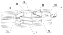
FIG. 1 is a schematic structural view of a continuous drilling device for a construction steel structure according to the present invention;
FIG. 2 is a schematic top view of a circular electric slide rail of the continuous drilling device for construction steel structure according to the present invention;
FIG. 3 is a schematic side view of a circular electric slide rail of the continuous drilling device for construction steel structure according to the present invention;
FIG. 4 is a schematic structural view of a punching frame of the continuous punching device for the construction steel structure provided by the invention;
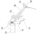
FIG. 5 is a schematic structural view of a support frame of the continuous drilling device for a construction steel structure according to the present invention;
FIG. 6 is a schematic structural view of a fixing frame of the continuous drilling device for the construction steel structure provided by the invention.
In the figure: the device comprises a shell 1, a hydraulic rod 2, a support frame 3, a first circular electric sliding rail 4, a collecting tank 5, an air inlet pipe 6, a blowing plate 7, a second circular electric sliding rail 8, a first motor 9, a first screw rod 10, a punching frame 11, a sliding rod 12, a first fixed support 13, a second fixed support 14, a pointer 15, an indication line 16, a mounting block 17, a sliding block 18, a punching head 19, a punching sleeve 20, a second motor 21, a threaded rod 22, a limiting sleeve 23, a sliding groove 24, an anti-skidding cushion 25, a sliding frame 26, a third motor 27, a third screw rod 28, a fixed frame 29, a first fixed plate 30, a second fixed plate 31, a connecting rod 32, a spring 33, a fixed rod 34, an arc clamping plate 35, an electric telescopic rod 36, a supporting plate.
Detailed Description
The technical solution of the present patent will be described in further detail with reference to the following embodiments.
Reference will now be made in detail to embodiments of the present patent, examples of which are illustrated in the accompanying drawings, wherein like or similar reference numerals refer to the same or similar elements or elements having the same or similar function throughout. The embodiments described below with reference to the drawings are exemplary only for the purpose of explaining the present patent and are not to be construed as limiting the present patent.
In the description of this patent, it is to be understood that the terms "center," "upper," "lower," "front," "rear," "left," "right," "vertical," "horizontal," "top," "bottom," "inner," "outer," and the like are used in the orientations and positional relationships indicated in the drawings for the convenience of describing the patent and for the simplicity of description, and are not intended to indicate or imply that the referenced devices or elements must have a particular orientation, be constructed and operated in a particular orientation, and are not to be considered limiting of the patent.
In the description of this patent, it is noted that unless otherwise specifically stated or limited, the terms "mounted," "connected," and "disposed" are to be construed broadly and can include, for example, fixedly connected, disposed, detachably connected, disposed, or integrally connected and disposed. The specific meaning of the above terms in this patent may be understood by those of ordinary skill in the art as appropriate.
Example 1:
a continuous perforating device for a steel structure for construction, as shown in figures 1, 2 and 3, comprises a shell 1, the two sides of the inner wall of the bottom of the shell 1 are respectively fixed with a support frame 3 through hydraulic rods 2, the outer wall of the top of the support frame 3 is provided with a fixing mechanism, the inner walls of the two sides of the shell 1 are respectively fixed with a first circular electric slide rail 4 and a second circular electric slide rail 8 through a first fixing support 13 and a second fixing support 14, the inner walls of one sides of the first circular electric slide rail 4 and the second circular electric slide rail 8 are respectively connected with a sliding block 18 in a sliding manner, the outer wall of one side of the sliding block 18 is fixed with mounting blocks 17 through bolts, the outer wall of one side of each of the two mounting blocks 17 is provided with the same moving assembly, the two mounting blocks 17 are provided with a punching frame 11 through the moving assemblies, the outer wall of one side of the punching frame 11 is provided; through being provided with circular electronic slide rail one 4 and circular electronic slide rail two 8, utilize circular electronic slide rail one 4 and circular electronic slide rail two 8 to be connected with the removal subassembly, utilize the removal subassembly to be connected with punching frame 11, be provided with the subassembly that punches on punching frame 11, the steel that will punch is put on two support frames 3, then utilize fixed establishment to fix it, utilize the height of 2 adjustment steel of hydraulic stem, then it is rotatory to utilize circular electronic slide rail one 4 and circular electronic slide rail two 8 to drive sliding block 18, thereby adjust the angle of punching head 19, utilize the removal subassembly to adjust the position of punching head 19, utilize the subassembly that punches at last.
In order to solve the problem that the punching position can be changed; as shown in fig. 2, the moving assembly comprises a first motor 9, a first screw rod 10 and a sliding rod 12, two ends of the sliding rod 12 are respectively connected with the outer wall of one side of the two mounting blocks 17, the first screw rod 10 is rotatably connected with the inner wall of one side of the two mounting blocks 17, the first motor 9 is fixed on the outer wall of one side of one of the mounting blocks 17 through a screw, a punching frame 11 is slidably connected with the outer wall of the circumference of the sliding rod 12, and the punching frame 11 is connected with the outer wall of the first screw rod 10 through a thread; through being provided with the removal subassembly, the removal subassembly is by motor 9, lead screw 10 and slide bar 12, and punching frame 11 passes through threaded connection in lead screw 10 outer wall, utilizes two installation pieces 17 to fix lead screw 10 and slide bar 12 on sliding block 18 to can control sliding block 18 and change the position of removal subassembly, the during operation, the starter motor drives lead screw 10 and rotates, thereby changes punching frame 11's position.
The punching machine aims to solve the problem of punching steel; as shown in fig. 4, the punching assembly comprises a punching head 19, a punching sleeve 20, a second motor 21, a threaded rod 22 and a limiting sleeve 23, the second motor 21 is fixed on the outer wall of the top of the punching frame 11 through screws, the limiting sleeve 23 is clamped on the inner wall of one side of the punching frame 11, an output shaft of the second motor 21 is connected with the threaded rod 22 through a coupler, the punching sleeve 20 is fixed on the outer wall of the threaded rod 22 through screws, the punching sleeve 20 is fixed on the inner wall of the limiting sleeve 23 through screws, the punching head 19 is fixed on the outer wall of one side of the punching sleeve 20, a collecting tank 5 is arranged on the inner wall of the bottom of the shell 1, a blowing plate 7 is fixed on the outer wall of the top of the shell 1 through screws; through being provided with the subassembly that punches, the subassembly that punches is by the head 19 that punches, punch sleeve 20, two 21 motors, threaded rod 22 and stop sleeve 23 are constituteed, to punch the head 19 and fix on punch sleeve 20, punch sleeve 20 under threaded rod 22 and stop sleeve 23's effect, can rotary motion, make punch head 19 punch to steel, set up collecting vat 5 and top setting blowing board 7 in 1 bottom of shell, from the top blow, blow into the collecting vat 5 with the impurity that produces and collect.
This embodiment is when using, the steel that will punch is put on two support frames 3, then it is fixed with it by fixed establishment, utilize the height of 2 adjustment steel of hydraulic stem, then it is rotatory to utilize two 8 drive sliding blocks of circular electronic slide rail 4 and circular electronic slide rail 18, thereby the angle of adjustment punching head 19, in operation, starter motor, drive a lead screw 10 and rotate, thereby change the position of punching frame 11, it fixes on punching sleeve 20 to punch head 19, punching sleeve 20 is under the effect of threaded rod 22 and stop sleeve 23, can rotary motion, make punching head 19 punch steel, set up collecting vat 5 and top in 1 bottom of shell and set up air-blowing plate 7, from the top air-blowing, blow into the impurity that produces and collect in the collecting vat 5.
Example 2:
a continuous perforating device for a steel structure for construction, as shown in figures 1, 5 and 6, aims to solve the problem of fixing steel; the present embodiment is modified from embodiment 1 as follows: each fixing mechanism comprises three sliding grooves 24, an anti-skidding cushion 25 and two clamping components respectively, the three sliding grooves 24 are arranged on the outer wall of the top of the support frame 3 respectively, the anti-skidding cushion 25 is welded at the central position of the inner wall of the top of the three sliding grooves 24, each clamping component comprises a fixing frame 29 and two sliding frames 26 respectively, the fixing frame 29 and the two sliding frames 26 are connected with the inner wall of one side of the three sliding grooves 24 in a sliding way, the inner wall of one side of one sliding groove 24 is rotatably connected with a third screw rod 28, the outer wall of one side of the support frame 3 is fixedly provided with a third motor 27 through screws, the output shaft of the third motor 27 is connected with the third screw rod 28 through a coupler, the two fixing frames 29 are fixedly arranged on the outer wall of the third screw rod 28 through threads respectively, the outer walls of the tops of the two, the first fixing plate 30 is matched with the second fixing plate 31, the two electric telescopic rods 36 are respectively connected with the first fixing plate 30 and the second fixing plate 31 through hinges, the fixing frame 29 is connected with the two sliding frames 26 through the two connecting rods 32, the inner wall of one side of each sliding frame 26 is respectively connected with a fixing rod 34 in a sliding mode, the outer wall of one side of each fixing rod 34 is welded with an arc-shaped clamping plate 35, the outer wall of the other side of each fixing rod 34 is clamped with a spring 33, each spring 33 is connected with the inner wall of one side of each sliding frame 26, each arc-shaped clamping plate 35, and the; including three sliding tray 24 respectively through being provided with fixed establishment, anti-skidding cushion 25 and two clamping components, put steel back on support frame 3, then starter motor three 27, make two mount 29 be close to each other, utilize two mount 29 to press from both sides tightly steel, four carriage 26 are also two liang close to each other, utilize arc cardboard 35 to further fix steel, the slipmat 38 that wherein sets up, a stability for improving the fixing, utilize electric telescopic handle 36 to fix fixed plate 30 and fixed plate two 31 at the steel top, both sides support about cooperation antiskid cushion 25 is to steel, prevent to cause vibrations from top to bottom when punching.
This embodiment is when using, put back on support frame 3 with steel, then three 27 starting motor, make two mount 29 be close to each other, utilize two mount 29 to press from both sides steel tightly, four carriage 26 are also two liang to be close to each other, utilize arc cardboard 35 to further fix steel, the slipmat 38 that wherein sets up, a stability for improve fixing, utilize electric telescopic handle 36 to fix fixed plate 30 and two 31 of fixed plate at the steel top, cooperation antiskid cushion 25 supports both sides about steel, prevent to cause vibrations from top to bottom when punching.
The above description is for the purpose of illustrating the preferred embodiments of the present invention and is not intended to limit the scope of the present invention, and any modifications, equivalents and improvements made by those skilled in the art within the spirit and scope of the present invention as disclosed herein, in combination with the prior art or common general knowledge, are intended to be included within the scope of the present invention.
Claims (9)
1. A continuous punching device for a steel structure for a building comprises a shell (1) and is characterized in that two sides of the inner wall of the bottom of the shell (1) are respectively fixed with a support frame (3) through a hydraulic rod (2), the outer wall of the top of the support frame (3) is provided with a fixing mechanism, the inner walls of two sides of the shell (1) are respectively fixed with a first circular electric slide rail (4) and a second circular electric slide rail (8) through a first fixing support (13) and a second fixing support (14), the inner walls of one sides of the first circular electric slide rail (4) and the second circular electric slide rail (8) are respectively connected with a sliding block (18) in a sliding manner, the outer wall of one side of the sliding block (18) is provided with a mounting block (17), the outer wall of one side of the two mounting blocks (17) is provided with a same moving assembly, the two mounting blocks, an indicating line (16) is arranged on the outer wall of one side of the first circular electric sliding rail (4), and a pointer (15) is arranged on a mounting block (17) on the first circular electric sliding rail (4).
2. The continuous perforating device for the steel structure for the building as recited in claim 1, wherein the moving assembly is composed of a first motor (9), a first screw rod (10) and a sliding rod (12), both ends of the sliding rod (12) are respectively connected with the outer wall of one side opposite to the two mounting blocks (17), the first screw rod (10) is rotatably connected with the inner wall of one side of the two mounting blocks (17), the first motor (9) is arranged on the outer wall of one side of one of the mounting blocks (17), the perforating frame (11) is slidably connected with the outer wall of the circumference of the sliding rod (12), and the perforating frame (11) is connected with the outer wall of the first screw rod (10) through threads.
3. The continuous perforating device for the steel structure for the building as recited in claim 1, wherein the perforating assembly is composed of a perforating head (19), a perforating sleeve (20), a second motor (21), a threaded rod (22) and a limiting sleeve (23), the second motor (21) is arranged on the outer wall of the top of the perforating frame (11), the limiting sleeve (23) is connected to the inner wall of one side of the perforating frame (11), an output shaft of the second motor (21) is connected with the threaded rod (22) through a coupler, the perforating sleeve (20) is fixed to the outer wall of the threaded rod (22) through threads, the perforating sleeve (20) is fixed to the inner wall of the limiting sleeve (23) through threads, and the perforating head (19) is fixed to the outer wall of one side of the perforating sleeve (20).
4. The continuous perforating device for the steel structure for the building as recited in claim 1, wherein the inner wall of the bottom of the housing (1) is provided with a collecting groove (5), the outer wall of the top of the housing (1) is provided with an air blowing plate (7), an air inlet of the air blowing plate (7) is clamped with an air inlet pipe (6), and the air inlet pipe (6) is connected with an external air pump.
5. The continuous perforating device for the steel structure for the building as recited in claim 1 wherein each of the fixing mechanisms comprises three sliding grooves (24), an anti-slip cushion (25) and two clamping components, the three sliding grooves (24) are respectively opened on the outer wall of the top of the supporting frame (3), and the anti-slip cushion (25) is arranged on the center of the inner wall of the top of the three sliding grooves (24).
6. The continuous perforating device for the steel structure for buildings as claimed in claim 5, characterized in that each of said clamping assemblies comprises a fixed frame (29) and two sliding frames (26), the fixed frame (29) and the two sliding frames (26) are slidably connected to the inner wall of one side of three sliding grooves (24), one side of the inner wall of one sliding groove (24) is rotatably connected with a third screw rod (28), the outer wall of one side of the supporting frame (3) is provided with a third motor (27), the output shaft of the third motor (27) is connected with the third screw rod (28) through a coupling, and the two fixed frames (29) are respectively fixed to the outer wall of the third screw rod (28) through threads.
7. The continuous perforating device for the steel structure for the building as recited in claim 6, wherein the two fixing frames (29) are respectively provided with a supporting plate (37) on the outer wall of the top portion, the outer wall of one side of the supporting plate (37) is hinged with an electric telescopic rod (36), the outer wall of the top portion of the two fixing frames (29) is respectively and rotatably connected with a first fixing plate (30) and a second fixing plate (31), the first fixing plate (30) and the second fixing plate (31) are matched, and the two electric telescopic rods (36) are respectively connected with the first fixing plate (30) and the second fixing plate (31) through hinges.
8. The continuous perforating device for the steel structure for building construction as claimed in claim 6, characterized in that said fixed frame (29) is connected with two sliding frames (26) by two connecting rods (32), a fixed rod (34) is slidably connected with the inner wall of one side of each sliding frame (26), an arc-shaped catch plate (35) is arranged on the outer wall of one side of the fixed rod (34), a spring (33) is clamped on the outer wall of the other side of the fixed rod (34), the spring (33) is connected with the inner wall of one side of the sliding frame (26), and each arc-shaped catch plate (35).
9. The continuous perforating device for the steel structure for construction as recited in claim 8, characterized in that a non-slip mat (38) is respectively disposed on an outer wall of one side of each of said fixing frame (29) and each of said arc-shaped clamping plates (35).
Priority Applications (1)
| Application Number | Priority Date | Filing Date | Title |
|---|---|---|---|
| CN202110426338.3A CN112872836A (en) | 2021-04-20 | 2021-04-20 | Continuous perforating device of steel construction for building |
Applications Claiming Priority (1)
| Application Number | Priority Date | Filing Date | Title |
|---|---|---|---|
| CN202110426338.3A CN112872836A (en) | 2021-04-20 | 2021-04-20 | Continuous perforating device of steel construction for building |
Publications (1)
| Publication Number | Publication Date |
|---|---|
| CN112872836A true CN112872836A (en) | 2021-06-01 |
Family
ID=76040813
Family Applications (1)
| Application Number | Title | Priority Date | Filing Date |
|---|---|---|---|
| CN202110426338.3A Withdrawn CN112872836A (en) | 2021-04-20 | 2021-04-20 | Continuous perforating device of steel construction for building |
Country Status (1)
| Country | Link |
|---|---|
| CN (1) | CN112872836A (en) |
Cited By (1)
| Publication number | Priority date | Publication date | Assignee | Title |
|---|---|---|---|---|
| CN113634786A (en) * | 2021-09-03 | 2021-11-12 | 安徽永茂泰汽车零部件有限公司 | Double-shaft drilling device for automobile parts and working method thereof |
-
2021
- 2021-04-20 CN CN202110426338.3A patent/CN112872836A/en not_active Withdrawn
Cited By (1)
| Publication number | Priority date | Publication date | Assignee | Title |
|---|---|---|---|---|
| CN113634786A (en) * | 2021-09-03 | 2021-11-12 | 安徽永茂泰汽车零部件有限公司 | Double-shaft drilling device for automobile parts and working method thereof |
Similar Documents
| Publication | Publication Date | Title |
|---|---|---|
| CN108031891A (en) | A kind of puncher for the processing of plate muscle | |
| CN111823330A (en) | Perforating device is used in furniture board production that can accurate location | |
| CN112872836A (en) | Continuous perforating device of steel construction for building | |
| CN214557585U (en) | Perforating device convenient to location for building engineering | |
| CN212169060U (en) | Electric power iron accessory staple bolt drilling equipment | |
| CN219466244U (en) | Plastic uptake piece bending, flattening and cutting device | |
| CN210731104U (en) | Drilling device for machining heater cylinder | |
| CN113399547A (en) | Continuous punching equipment for pipe fittings | |
| CN218363392U (en) | Connecting plate boring grab device for machining | |
| CN213195358U (en) | Positioning device for split hoop machine | |
| CN220077812U (en) | Unloader convenient to installation | |
| CN219966509U (en) | Cell-phone center perforating device | |
| CN213576580U (en) | Ultrasonic positioning auxiliary calibration system | |
| CN218425740U (en) | Perforating device is used in centrifugal fan production of airing exhaust | |
| CN219945270U (en) | Positioning assembly for roller milling machine | |
| CN215392586U (en) | Hinge plate drilling and tapping device | |
| CN219297852U (en) | Yarn end removing device for towel production | |
| CN215788394U (en) | Drilling machine for pan | |
| CN220052127U (en) | High-efficient furniture panel drilling equipment | |
| CN213262635U (en) | Guardrail device for engineering vehicle | |
| CN218327147U (en) | Circulating water pump's device of making an uproar that falls | |
| CN214979299U (en) | Clamping device for steel hydraulic puncher | |
| CN215747938U (en) | Multifunctional plate pipe cutting platform | |
| CN217222743U (en) | Electrical installation is with inhaling grey equipment | |
| CN219310261U (en) | Tapping machine suitable for multi-angle hole |
Legal Events
| Date | Code | Title | Description |
|---|---|---|---|
| PB01 | Publication | ||
| PB01 | Publication | ||
| SE01 | Entry into force of request for substantive examination | ||
| SE01 | Entry into force of request for substantive examination | ||
| WW01 | Invention patent application withdrawn after publication | ||
| WW01 | Invention patent application withdrawn after publication |
Application publication date: 20210601 |