CN112871295B - Medical treatment medicine amoxicillin grinding device - Google Patents
Medical treatment medicine amoxicillin grinding device Download PDFInfo
- Publication number
- CN112871295B CN112871295B CN202110094679.5A CN202110094679A CN112871295B CN 112871295 B CN112871295 B CN 112871295B CN 202110094679 A CN202110094679 A CN 202110094679A CN 112871295 B CN112871295 B CN 112871295B
- Authority
- CN
- China
- Prior art keywords
- rod
- bearing plate
- amoxicillin
- material bearing
- matched
- Prior art date
- Legal status (The legal status is an assumption and is not a legal conclusion. Google has not performed a legal analysis and makes no representation as to the accuracy of the status listed.)
- Active
Links
- 239000003814 drug Substances 0.000 title claims abstract description 50
- LSQZJLSUYDQPKJ-NJBDSQKTSA-N amoxicillin Chemical compound C1([C@@H](N)C(=O)N[C@H]2[C@H]3SC([C@@H](N3C2=O)C(O)=O)(C)C)=CC=C(O)C=C1 LSQZJLSUYDQPKJ-NJBDSQKTSA-N 0.000 title claims abstract description 47
- 229960003022 amoxicillin Drugs 0.000 title claims abstract description 47
- LSQZJLSUYDQPKJ-UHFFFAOYSA-N p-Hydroxyampicillin Natural products O=C1N2C(C(O)=O)C(C)(C)SC2C1NC(=O)C(N)C1=CC=C(O)C=C1 LSQZJLSUYDQPKJ-UHFFFAOYSA-N 0.000 title claims abstract description 47
- 238000000227 grinding Methods 0.000 title claims abstract description 33
- 230000007246 mechanism Effects 0.000 claims abstract description 93
- 239000000463 material Substances 0.000 claims abstract description 48
- 238000005096 rolling process Methods 0.000 claims abstract description 29
- 230000006835 compression Effects 0.000 claims description 66
- 238000007906 compression Methods 0.000 claims description 66
- 238000001125 extrusion Methods 0.000 claims description 41
- 230000005540 biological transmission Effects 0.000 claims description 23
- 238000003860 storage Methods 0.000 claims description 22
- 238000003756 stirring Methods 0.000 claims description 3
- 239000000843 powder Substances 0.000 abstract description 14
- 238000007790 scraping Methods 0.000 description 13
- 229940079593 drug Drugs 0.000 description 10
- 230000000694 effects Effects 0.000 description 7
- 230000005484 gravity Effects 0.000 description 7
- 239000003638 chemical reducing agent Substances 0.000 description 2
- 230000033001 locomotion Effects 0.000 description 2
- 229930182555 Penicillin Natural products 0.000 description 1
- 230000009471 action Effects 0.000 description 1
- 230000004075 alteration Effects 0.000 description 1
- 239000003242 anti bacterial agent Substances 0.000 description 1
- 230000009286 beneficial effect Effects 0.000 description 1
- 230000003115 biocidal effect Effects 0.000 description 1
- 230000003139 buffering effect Effects 0.000 description 1
- 210000002421 cell wall Anatomy 0.000 description 1
- 230000008878 coupling Effects 0.000 description 1
- 238000010168 coupling process Methods 0.000 description 1
- 238000005859 coupling reaction Methods 0.000 description 1
- 230000007547 defect Effects 0.000 description 1
- 238000005516 engineering process Methods 0.000 description 1
- 239000012634 fragment Substances 0.000 description 1
- 238000004519 manufacturing process Methods 0.000 description 1
- 238000012986 modification Methods 0.000 description 1
- 230000004048 modification Effects 0.000 description 1
- 230000000149 penetrating effect Effects 0.000 description 1
- 150000002960 penicillins Chemical class 0.000 description 1
- 238000003825 pressing Methods 0.000 description 1
- 230000001954 sterilising effect Effects 0.000 description 1
- 238000004659 sterilization and disinfection Methods 0.000 description 1
- 238000006467 substitution reaction Methods 0.000 description 1
- 239000005341 toughened glass Substances 0.000 description 1
- 239000002699 waste material Substances 0.000 description 1
Images




Classifications
-
- B—PERFORMING OPERATIONS; TRANSPORTING
- B02—CRUSHING, PULVERISING, OR DISINTEGRATING; PREPARATORY TREATMENT OF GRAIN FOR MILLING
- B02C—CRUSHING, PULVERISING, OR DISINTEGRATING IN GENERAL; MILLING GRAIN
- B02C4/00—Crushing or disintegrating by roller mills
- B02C4/02—Crushing or disintegrating by roller mills with two or more rollers
- B02C4/08—Crushing or disintegrating by roller mills with two or more rollers with co-operating corrugated or toothed crushing-rollers
-
- B—PERFORMING OPERATIONS; TRANSPORTING
- B02—CRUSHING, PULVERISING, OR DISINTEGRATING; PREPARATORY TREATMENT OF GRAIN FOR MILLING
- B02C—CRUSHING, PULVERISING, OR DISINTEGRATING IN GENERAL; MILLING GRAIN
- B02C21/00—Disintegrating plant with or without drying of the material
-
- B—PERFORMING OPERATIONS; TRANSPORTING
- B02—CRUSHING, PULVERISING, OR DISINTEGRATING; PREPARATORY TREATMENT OF GRAIN FOR MILLING
- B02C—CRUSHING, PULVERISING, OR DISINTEGRATING IN GENERAL; MILLING GRAIN
- B02C4/00—Crushing or disintegrating by roller mills
- B02C4/10—Crushing or disintegrating by roller mills with a roller co-operating with a stationary member
-
- B—PERFORMING OPERATIONS; TRANSPORTING
- B02—CRUSHING, PULVERISING, OR DISINTEGRATING; PREPARATORY TREATMENT OF GRAIN FOR MILLING
- B02C—CRUSHING, PULVERISING, OR DISINTEGRATING IN GENERAL; MILLING GRAIN
- B02C4/00—Crushing or disintegrating by roller mills
- B02C4/28—Details
- B02C4/30—Shape or construction of rollers
Landscapes
- Engineering & Computer Science (AREA)
- Food Science & Technology (AREA)
- Basic Packing Technique (AREA)
Abstract
The invention relates to grinding equipment, in particular to medical medicine amoxicillin grinding equipment. The invention provides a medical medicine amoxicillin grinding device which can automatically grind and scrape materials and can automatically collect materials. The utility model provides a medical treatment medicine amoxicillin grinding device, is connected with the backup pad between two brace table lower parts including brace table and backup pad, and the backup pad top is equipped with pulling mechanism, is connected with rolling mechanism between two brace tables, and rolling mechanism is connected with pulling mechanism. According to the invention, the pulling mechanism and the rolling mechanism are arranged, the rolling mechanism is driven to operate by the operation of the pulling mechanism, the rolling mechanism repeatedly rolls amoxicillin, so that amoxicillin is ground into powder, and the aim of automatic grinding is achieved.
Description
Technical Field
The invention relates to grinding equipment, in particular to medical medicine amoxicillin grinding equipment.
Background
The amoxicillin is an antibiotic drug, has strong sterilization effect and strong cell wall penetrating capability, is one of oral penicillins widely applied at present, and in the production process of amoxicillin, massive amoxicillin needs to be ground into powder, but a common grinder needs to be continuously pushed and pulled by workers to perform grinding operation under the action of gravity and friction force, so that the grinding efficiency is low, the working labor intensity is high, and the labor cost is high.
Patent application CN108176461A, publication number is 2018.06.19, disclose a medicine grinder for medical treatment, including the lapping plate, a machine support, transparent toughened glass, a motor, a speed reducer, the speed reducer main shaft, screw thread adjustment mechanism, first rotation axis and buffering formula coupling mechanism etc., use through the cooperation of hopper and flexible pipe down, can not cause granular or foliate traditional chinese medicine to spill, be convenient for place the inside of grinding the groove with traditional chinese medicine rapidly, then adjust screw thread adjustment mechanism and provide required pressure, open the motor afterwards, at this moment, under the effect of motor, the grinding wheel is the rotation of circular, under the effect of frictional force and gravity, play effectual grinding effect, however, after the device grinds, need artifical manual scraping and collecting, waste time and energy.
Therefore, the development of a medical drug amoxicillin grinding device which can automatically grind, automatically scrape and automatically collect is urgently needed.
Disclosure of Invention
The invention aims to provide medical medicine amoxicillin grinding equipment capable of automatically grinding, scraping and collecting, and aims to overcome the defects of low manual grinding efficiency, high labor intensity and high cost in the background technology.
In order to achieve the purpose, the invention provides the following technical scheme: the utility model provides a medical treatment medicine amoxicillin grinding device, is connected with the backup pad between two brace table lower parts including brace table and backup pad, and the backup pad top is equipped with pulling mechanism, is connected with rolling mechanism between two brace tables, and rolling mechanism is connected with pulling mechanism.
Optionally, an air cylinder is arranged on the inner side of the upper portion of the supporting plate, a first pull rod is arranged on the rolling mechanism and connected with the air cylinder, two extrusion rods are arranged on the first pull rod, a first rack is arranged on the extrusion rod on one side, and two shifting blocks are arranged on the first pull rod.
Optionally, fixed frames are arranged on the upper portion of the inner side of each support platform, a material bearing plate is connected between the two support platforms, a roller is connected between the two fixed frames in a sliding mode and is connected with the first pull rod, the roller is matched with the material bearing plate, two first full gears are arranged on the roller, two second racks are arranged on the material bearing plate, and the second racks are meshed with the first full gears.
Optionally, be connected with the feeding case between two brace table upper portions, the inboard rotary type in brace table upper portion that is close to one side of first rack is equipped with first transmission shaft, be equipped with one-way gear in the first transmission shaft, one-way gear and first rack toothing, feeding incasement portion rotary type is connected with two secondary drive shafts, all be equipped with the extrusion piece on two secondary drive shafts, two extrusion pieces are mutually supported, be connected with belt assembly between the secondary drive shaft that is close to one side of cylinder and the first transmission shaft, all be equipped with the second all-gear on two secondary drive shafts, two second all-gear intermeshing.
Optionally, three first fixing frames are arranged at the bottom of the material bearing plate, a vibration rod is arranged inside the first fixing frames in a sliding mode and matched with the extrusion rod and the material bearing plate, two first compression springs are wound on the vibration rod, the tops of the first compression springs are connected with the vibration rod, and the bottoms of the first compression springs are connected with the first fixing frames.
Optionally, two second pull rods are slidably arranged on the inner side of the material bearing plate, a second compression spring is wound on the second pull rods and connected between the second pull rods and the material bearing plate, a scraper is connected between the two second pull rods and matched with the material bearing plate, two first fixed blocks are arranged on the fixed frame, a first connecting rod is connected between the two extrusion rods, a second connecting rod is slidably connected inside the first connecting rod and matched with the first fixed block, two first clamping blocks are arranged on the inner side of the upper portion of the second connecting rod and slidably connected with the first connecting rod, the first clamping blocks are matched with the scraper, a third compression spring is wound on each of the two first clamping blocks, the bottom of the third compression spring is connected with the second connecting rod, and the top of the third compression spring is connected with the first connecting rod.
Optionally, the inboard slidingtype of feeding case is equipped with two third connecting rods, be equipped with two second fixed blocks on the feeding case, all be equipped with the link on two third connecting rods, be connected with the baffle between two links, baffle and feeding case slidingtype connection, all around having fourth compression spring on two third connecting rods, fourth compression spring connects between third connecting rod and feeding case, the inboard slidingtype of link is equipped with the second fixture block, second fixture block and second fixed block and the cooperation of stirring the piece, around having fifth compression spring on the second fixture block, fifth compression spring connects between link and second fixture block.
Optionally, two second fixing frames are arranged on the material bearing plate, a storage box is connected between the two second fixing frames in a sliding mode, the storage box is matched with the material bearing plate, a stop block is arranged on the material bearing plate, and the stop block is matched with the storage box.
Compared with the prior art, the invention has the beneficial effects that:
1. the amoxicillin powder grinding machine is provided with the pulling mechanism and the grinding mechanism, wherein the pulling mechanism operates to drive the grinding mechanism to operate, and the grinding mechanism repeatedly grinds amoxicillin powder to achieve the purpose of automatic grinding;
2. the amoxicillin drug grinding device is provided with the extrusion mechanism, the pulling mechanism operates to drive the extrusion mechanism to operate, so that amoxicillin drugs are extruded, the purpose of automatic extrusion is achieved, and the amoxicillin drugs can be ground more fully;
3. according to the invention, the vibrating mechanism is arranged, the pulling mechanism operates to drive the vibrating mechanism to operate, so that part of the rolling mechanism vibrates, and the ground medicine powder can be prevented from being stuck in the rolling mechanism;
4. according to the automatic medicine powder scraping mechanism, the scraping mechanism is arranged, the pulling mechanism operates to drive the scraping mechanism to operate, and the scraping mechanism scrapes medicine powder in the grinding mechanism, so that the automatic material scraping effect is achieved;
5. according to the invention, the opening and closing mechanism is arranged, and the pulling mechanism operates to drive the opening and closing mechanism to operate, so that the extruded medicine intermittently falls into the rolling mechanism from the extrusion mechanism, and the intermittent blanking effect is achieved;
6. according to the invention, the storage mechanism is arranged, so that when the scraping mechanism scrapes off the medicine powder in the rolling mechanism, the medicine powder falls into the storage mechanism due to gravity, and the storage mechanism collects the medicine powder, thereby achieving the effect of automatic collection.
Drawings
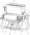
Fig. 1 is a schematic perspective view of the present invention.
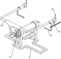
Fig. 2 is a schematic perspective view of the pulling mechanism of the present invention.
Fig. 3 is a schematic perspective view of the rolling mechanism of the present invention.
Fig. 4 is a schematic perspective view of the extrusion mechanism of the present invention.
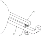
Fig. 5 is a schematic perspective view of a first part of the vibration mechanism of the present invention.
Fig. 6 is a schematic perspective view of a second part of the vibration mechanism of the present invention.
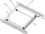
Fig. 7 is a schematic perspective view of a first part of the scraping mechanism of the present invention.
Fig. 8 is a schematic perspective view of a part of a second scraping mechanism according to the present invention.
Fig. 9 is a schematic view of a first partial structure of the opening and closing mechanism of the present invention.
Fig. 10 is a schematic perspective view of a second mechanism of the opening and closing mechanism of the present invention.
Fig. 11 is a schematic perspective view of a third opening and closing mechanism of the present invention.
Fig. 12 is a schematic perspective view of the storage mechanism of the present invention.
The meaning of the reference symbols in the figures: 1: support table, 2: support plate, 3: pulling mechanism, 31: cylinder, 32: first link, 33: extrusion stem, 34: first rack, 35: toggle block, 4: rolling mechanism, 41: fixing frame, 42: material-receiving plate, 43: drum, 44: first full gear, 45: second rack, 5: pressing mechanism, 51: feed box, 52: first transmission shaft, 521: one-way gear, 53: second drive shaft, 54: belt assembly, 55: extrusion block, 56: second full gear, 6: vibration mechanism, 61: first mount, 62: vibration rod, 63: first compression spring, 7: scraping mechanism, 71: second tie rod, 72: first fixing block, 73: second compression spring, 74: scraper, 75: first connecting rod, 76: second connecting rod, 77: first latch, 78: third compression spring, 8: opening and closing mechanism, 81: third connecting rod, 82: second fixed block, 83: connecting frame, 84: fourth compression spring, 85: second latch, 86: fifth compression spring, 87: baffle, 9: storage mechanism, 91: second mount, 92: stopper, 93: and a storage box.
Detailed Description
The technical solutions in the embodiments of the present invention will be clearly and completely described below with reference to the drawings in the embodiments of the present invention, and it is obvious that the described embodiments are only a part of the embodiments of the present invention, and not all of the embodiments. All other embodiments, which can be derived by a person skilled in the art from the embodiments given herein without making any creative effort, shall fall within the protection scope of the present invention.
Referring to fig. 1-12, the present invention provides a technical solution: the utility model provides a medical medicine amoxicillin grinding device, including brace table 1, backup pad 2, pulling mechanism 3, cylinder 31, first pull rod 32, extrusion stem 33, first rack 34, stir movable block 35, rolling mechanism 4, fixed frame 41, hold flitch 42, cylinder 43, first full gear 44, second rack 45, extrusion mechanism 5, feed box 51, first transmission shaft 52, one-way gear 521, second transmission shaft 53, belt subassembly 54, extrusion block 55, second full gear 56, vibrations mechanism 6, first mount 61, vibrations pole 62, first compression spring 63, scraping mechanism 7, second pull rod 71, first fixed block 72, second compression spring 73, scraper 74, first connecting rod 75, second connecting rod 76, first fixture block 77, third compression spring 78, mechanism 8 opens and shuts, third connecting rod 81, second fixed block 82, link 83, fourth compression spring 84, second compression spring fixture block 85, fifth compression spring fixture block 86, baffle 87, storage mechanism 9, second fixture block 91, second fixture 92, open and shut mechanism 93, two connection box 2 is connected with between the lower part of support table 1 and the rolling mechanism 3, the top of pulling mechanism 4 is connected with the rolling mechanism 3.
The cylinder 31 is arranged on the inner side of the upper portion of the supporting plate 2, the first pull rod 32 is arranged on the rolling mechanism 4, the first pull rod 32 is connected with the rear side of the cylinder 31, the extrusion rods 33 are arranged on the left and right sides of the front portion of the first pull rod 32, a first rack 34 is arranged on the left side of the left extrusion rod 33, and the toggle blocks 35 are arranged on the left and right sides of the upper portion of the front side of the first pull rod 32.
The upper portion of the inner side of each supporting platform 1 is provided with a fixing frame 41, a material bearing plate 42 is connected between the two supporting platforms 1, the fixing frames 41 on the left side and the right side are connected with a roller 43 in a sliding mode, the roller 43 is connected with the first pull rod 32, the roller 43 is matched with the material bearing plate 42, the left side and the right side of the roller 43 are provided with first full gears 44, the left side and the right side of the top of the material bearing plate 42 are provided with second racks 45, and the second racks 45 are meshed with the first full gears 44.
Be connected with feeding case 51 between two brace table 1 upper portions, the inboard rotary type in left brace table 1 upper portion is equipped with first transmission shaft 52, first transmission shaft 52 right side is equipped with one-way gear 521, one-way gear 521 meshes with first rack 34, the rotary type is connected with two second transmission shafts 53 between the inside left and right sides of feeding case 51, all be equipped with extrusion piece 55 on the second transmission shaft 53 of front and back both sides, two extrusion piece 55 are mutually supported, be connected with belt assembly 54 between the second transmission shaft 53 left part of front side and the first transmission shaft 52, two second transmission shaft 53 left parts all are equipped with second full gear 56, the second full gear 56 intermeshing of front and back both sides.
Three first fixing frames 61 are arranged at the bottom of the material bearing plate 42, a vibration rod 62 is arranged on the inner side of the first fixing frame 61 in a sliding mode, the vibration rod 62 is matched with the extrusion rod 33 and the material bearing plate 42, two first compression springs 63 are wound on the vibration rod 62, the tops of the first compression springs 63 are connected with the vibration rod 62, and the bottoms of the first compression springs 63 are connected with the first fixing frames 61.
Two second pull rods 71 are slidably arranged on the inner side of the rear portion of the material bearing plate 42, a second compression spring 73 is wound on the rear portion of each second pull rod 71, the second compression springs 73 are connected between the second pull rods 71 and the material bearing plate 42, scrapers 74 are connected between the front sides of the second pull rods 71 on the left side and the right side, the scrapers 74 are matched with the material bearing plate 42, first fixing blocks 72 are arranged on the left side and the right side of the front portion of the bottom side of the fixing frame 41, first connecting rods 75 are connected between the extrusion rods 33 on the left side and the right side, second connecting rods 76 are slidably connected inside the first connecting rods 75 and are matched with the first fixing blocks 72, two first clamping blocks 77 are arranged on the inner side of the upper portion of each second connecting rod 76, the first clamping blocks 77 are slidably connected with the first connecting rods 75, the first clamping blocks 77 are matched with the scrapers 74, third compression springs 78 are wound on the first clamping blocks 77 on the left side and the right side, the bottom of each third compression spring 78 is connected with the second connecting rods 76, and the top of each third compression spring 78 is connected with the first connecting rods 75.
Third connecting rods 81 are arranged on the inner sides of the lower portions of the left side and the right side of the feeding box 51 in a sliding mode, second fixing blocks 82 are arranged on the rear sides of the lower portions of the left side and the right side of the feeding box 51 in a sliding mode, connecting frames 83 are arranged on the front sides of the third connecting rods 81 of the left side and the right side, baffle plates 87 are connected between the connecting frames 83 of the left side and the right side, the baffle plates 87 are connected with the feeding box 51 in a sliding mode, fourth compression springs 84 are wound on the two third connecting rods 81, the fourth compression springs 84 are connected between the third connecting rods 81 and the feeding box 51, second clamping blocks 85 are arranged on the inner sides of the connecting frames 83 in a sliding mode, the second clamping blocks 85 are matched with the second fixing blocks 82 and the poking block 35, fifth compression springs 86 are wound on the second clamping blocks 85, and the fifth compression springs 86 are connected between the connecting frames 83 and the second clamping blocks 85.
Two second fixing frames 91 are arranged at the front part of the bottom side of the material bearing plate 42, a storage box 93 is connected between the second fixing frames 91 at the left side and the right side in a sliding manner, the storage box 93 is matched with the material bearing plate 42, a stop block 92 is arranged at the left side of the front part of the bottom side of the material bearing plate 42, and the stop block 92 is matched with the storage box 93.
When people need grind the medical medicine amoxicillin, at first people put the amoxicillin medicine in rolling mechanism 4, then make pulling mechanism 3 operate, pulling mechanism 3 operates and drives rolling mechanism 4 to operate, rolling mechanism 4 rolls repeatedly the amoxicillin medicine, thereby grind it into powder, so reached the purpose of high-efficient grinding, later people manually scrape powdered amoxicillin in rolling mechanism 4 off, and collect it, if people still need grind the amoxicillin medicine, can continue to put unground amoxicillin medicine in rolling mechanism 4, if amoxicillin medicine grinding work has all been accomplished, people make pulling mechanism 3 stop operating, thereby make rolling mechanism 4 stop operating, if use this equipment once more, can repeatedly above-mentioned step.
After people put the amoxicillin medicine, open cylinder 31, cylinder 31 function can make first pull rod 32 remove repeatedly from beginning to end, and then make extrusion stem 33 and dial piece 35 remove repeatedly from beginning to end, left extrusion stem 33 removes and makes first rack 34 remove repeatedly from beginning to end, first pull rod 32 removes and makes partial rolling mechanism 4 operation in addition, and then roll the amoxicillin medicine repeatedly, thereby grind it into powder, treat that the work of grinding is whole to be accomplished the back, people close cylinder 31, make first rack 34 and dial piece 35 stop motion, make rolling mechanism 4 stall simultaneously, the operation so, time saving and labor saving.
The amoxicillin medicine is placed on the top of the material bearing plate 42, when the first pull rod 32 moves backwards, the first pull rod 32 makes the roller 43 slide backwards in the fixing frame 41, the roller 43 moves to drive the first full gear 44 to move backwards, as the first full gear 44 is meshed with the second rack 45, the second rack 45 makes the first full gear 44 rotate and further makes the roller 43 rotate, when the first pull rod 32 moves forwards, the first pull rod 32 makes the roller 43 and the first full gear 44 move forwards, and simultaneously the second rack 45 makes the first full gear 44 rotate backwards, and further makes the roller 43 rotate backwards, during the movement and rotation of the roller 43, the roller 43 is matched with the material bearing plate 42, and further the amoxicillin medicine on the top of the material bearing plate 42 is repeatedly rolled, so that the amoxicillin medicine is ground into powder, then the powdery amoxicillin on the top of the material bearing plate 42 is manually scraped off and is collected, thus the purpose of automatic grinding is achieved.
When the first rack 34 moves forwards to be meshed with the one-way gear 521, the first rack 34 moves to enable the one-way gear 521 to rotate, the first transmission shaft 52 rotates, the belt assembly 54 rotates, the second transmission shaft 53 on the front side rotates to drive the second full gear 56 on the front side to rotate with the extrusion block 55, the second full gears 56 on the front side and the rear side are meshed with each other, the second full gear 56 on the front side rotates to drive the second full gear 56 on the rear side to rotate, the second transmission shaft 53 on the rear side rotates, the extrusion blocks 55 on the rear side rotate, the extrusion blocks 55 on the front side and the rear side rotate to extrude the amoxicillin, the amoxicillin medicines after extrusion fall from between the two extrusion blocks 55 to the top of the material bearing plate 42 due to gravity, the roller 43 rolls the amoxicillin medicines, and the purpose of automatic extrusion is achieved, so that the amoxicillin medicines can be ground more fully, when the first rack 34 moves backwards to be meshed with the first rack 55, and the first full-way extrusion block 521 does not rotate after extrusion due to enable the amoxicillin medicines to idle rotation.
When the extrusion rod 33 moves to contact with the vibration rod 62, the extrusion rod 33 enables the vibration rod 62 to slide downwards in the first fixing frame 61, the first compression spring 63 is changed from an initial state to a compressed state, when the extrusion rod 33 is separated from the vibration rod 62, the first compression spring 63 is reset from the compressed state, the vibration rod 62 moves back upwards to the original position due to the elastic force, due to the influence of inertia, the vibration rod 62 moves upwards to impact the material bearing plate 42 in a small amplitude, and then the material bearing plate 42 is vibrated, so that the ground medicine powder can be prevented from being stuck on the material bearing plate 42.
In the initial state, since the second connecting rod 76 is engaged with the first fixing block 72, the third compression spring 78 is in a compressed state, when the extruding rod 33 moves backward, the extruding rod 33 drives the first connecting rod 75 to move backward, and further the second connecting rod 76 moves backward, so that the first clamping block 77 and the third compression spring 78 move backward, when the second connecting rod 76 is separated from the first fixing block 72, the third compression spring 78 is reset from the compressed state, the elastic force moves the second connecting rod 76 downward, so that the first clamping block 77 moves downward, and the roller 43 moves backward and rolls the drugs, when the first clamping block 77 moves to contact with the scraper 74, the scraper 74 resets the first clamping block 77 to slide upward in the first connecting rod 75, so that the second connecting rod 76 moves upward, and simultaneously the third compression spring 78 changes from the initial state to the compressed state, when the first clamping block 77 and the scraper 74 move away from the scraper 74, the third compression spring 78 is reset from the compressed state, and when the first clamping block 77 and the scraper 74 move away from the scraper 74, the first clamping block 77 and the scraper 74 move forward, so that the second clamping block 77 and the scraper 74 move forward, and the second clamping rod 76 move forward, and the scraper 72, so that the second clamping rod 74 and the scraper 72 move forward, and the second clamping rod 74 move forward, and the scraper rod 73 move forward, and the first clamping rod 71 move forward, and the second clamping block 72, and the scraper rod 72 move forward, and the scraper rod 72 move forward, and the second clamping rod 72, and the scraper 74 move forward, and the second clamping rod 71 move manually, and then the first block 77 slides upwards in the scraper 74, the third compression spring 78 is changed from the initial state to the compression state, and when the first block 77 is separated from the scraper 74, the second compression spring 73 is reset from the compression state, and the elastic force enables the second pull rod 71 and the scraper 74 to move back to the original position, so that the purpose of automatic scraping is achieved.
When the shifting block 35 and the first rack 34 move forward, the extruding blocks 55 extrude the amoxicillin, the crushed amoxicillin falls from between the two extruding blocks 55 to the top of the baffle 87 due to gravity, when the shifting block 35 moves forward to contact with the second fixture block 85, the shifting block 35 enables the second fixture block 85 to slide upward in the connecting frame 83, the fifth compression spring 86 is changed from the initial state to the compression state, when the shifting block 35 is separated from the second fixture block 85, the fifth compression spring 86 is reset from the compression state, the second fixture block 85 moves back to the original position downward due to the elastic force, when the shifting block 35 moves backward to contact with the second fixture block 85, the shifting block 35 pushes the second fixture block 85 to move backward, so that the connecting frame 83 moves backward, the third connecting rod 81 slides backward in the feeding box 51, and the fourth compression spring 84 is changed from the initial state to the compression state, meanwhile, the connecting frame 83 enables the baffle 87 to slide backwards in the feeding box 51, fragments of amoxicillin medicine on the top of the baffle 87 drop to the top of the material supporting plate 42 due to gravity, when the second fixture block 85 moves to be in contact with the second fixing block 82, the second fixing block 82 enables the second fixture block 85 to slide upwards in the connecting frame 83, the fifth compression spring 86 is changed from an initial state to a compressed state, then the shifting block 35 is separated from the second fixture block 85, the fourth compression spring 84 is reset from the compressed state, the connecting frame 83 and the baffle 87 are moved back to the original position due to the elastic force, the second fixture block 85 is moved forwards by the connecting frame 83, and the fifth compression spring 86 is reset from the compressed state, so that the second fixture block 85 is reset to the original position, the purpose of intermittent blanking is achieved, and the situation that the medicine which is not ground can be scraped off from the material supporting plate 42 by the scraper 74 can be prevented.
When the scraper 74 moves forwards, the scraper 74 enables the powdery amoxicillin medicine on the material bearing plate 42 to move forwards, then the powdery medicine falls into the storage box 93 from the material bearing plate 42 due to gravity, the storage box 93 collects the powdery amoxicillin medicine, and therefore the purpose of automatic collection is achieved, after sufficient powdery amoxicillin medicine is accumulated in the storage box 93, people manually slide the storage box 93 out of the second fixing frame 91 to the right, people pour out the powdery amoxicillin medicine again, then the storage box 93 moves back to the original position, and at the moment, the stop block 92 can prevent the storage box 93 from moving too much to the left.
Although embodiments of the present invention have been shown and described, it will be appreciated by those skilled in the art that changes, modifications, substitutions and alterations can be made in these embodiments without departing from the principles and spirit of the invention, the scope of which is defined in the appended claims and their equivalents.
Claims (2)
1. The medical medicine amoxicillin grinding equipment comprises support tables (1) and support plates (2), and is characterized in that the support plates (2) are connected between the lower parts of the two support tables (1), a pulling mechanism (3) is arranged at the top of the support plates (2), a rolling mechanism (4) is connected between the two support tables (1), and the rolling mechanism (4) is connected with the pulling mechanism (3); an air cylinder (31) is arranged on the inner side of the upper portion of the supporting plate (2), a first pull rod (32) is arranged on the rolling mechanism (4), the first pull rod (32) is connected with the air cylinder (31), two extrusion rods (33) are arranged on the first pull rod (32), a first rack (34) is arranged on the extrusion rod (33) on one side, and two shifting blocks (35) are arranged on the first pull rod (32); the upper part of the inner side of each support platform (1) is provided with a fixed frame (41), a material bearing plate (42) is connected between the two support platforms (1), a roller (43) is connected between the two fixed frames (41) in a sliding manner, the roller (43) is connected with a first pull rod (32), the roller (43) is matched with the material bearing plate (42), the roller (43) is provided with two first full gears (44), the material bearing plate (42) is provided with two second racks (45), and the second racks (45) are meshed with the first full gears (44); a feeding box (51) is connected between the upper parts of the two supporting tables (1), a first transmission shaft (52) is rotatably arranged on the inner side of the upper part of the supporting table (1) close to one side of the first rack (34), a one-way gear (521) is arranged on the first transmission shaft (52), the one-way gear (521) is meshed with the first rack (34), two second transmission shafts (53) are rotatably connected in the feeding box (51), extrusion blocks (55) are arranged on the two second transmission shafts (53), the two extrusion blocks (55) are matched with each other, a belt assembly (54) is connected between the second transmission shaft (53) close to one side of the roller (43) and the first transmission shaft (52), second full gears (56) are arranged on the two second transmission shafts (53), and the two second full gears (56) are meshed with each other; three first fixing frames (61) are arranged at the bottom of the material bearing plate (42), a vibration rod (62) is arranged on the inner side of each first fixing frame (61) in a sliding mode, the vibration rod (62) is matched with the extrusion rod (33) and the material bearing plate (42), two first compression springs (63) are wound on the vibration rod (62), the tops of the first compression springs (63) are connected with the vibration rod (62), and the bottoms of the first compression springs (63) are connected with the first fixing frames (61); two second pull rods (71) are arranged on the inner side of the material bearing plate (42) in a sliding mode, a second compression spring (73) is wound on each second pull rod (71), the second compression spring (73) is connected between each second pull rod (71) and the material bearing plate (42), a scraper (74) is connected between each second pull rod (71), the scraper (74) is matched with the material bearing plate (42), two first fixing blocks (72) are arranged on the fixing frame (41), a first connecting rod (75) is connected between each two extrusion rods (33), a second connecting rod (76) is connected inside each first connecting rod (75) in a sliding mode, the second connecting rod (76) is matched with the first fixing blocks (72), two first clamping blocks (77) are arranged on the inner side of the upper portion of each second connecting rod (76), each first clamping block (77) is connected with the corresponding first connecting rod (75) in a sliding mode, each first clamping block (77) is matched with the scraper (74), third compression springs (78) are wound on the two first clamping blocks (77), the bottoms of the third compression springs (78) are connected with the second connecting rods (76), and the tops of the third compression springs (78) are connected with the top portions of the second connecting rods (75); feeding case (51) inboard slidingtype is equipped with two third connecting rods (81), be equipped with two second fixed blocks (82) on feeding case (51), all be equipped with link (83) on two third connecting rods (81), be connected with baffle (87) between two link (83), baffle (87) and feeding case (51) slidingtype connection, all around fourth compression spring (84) on two third connecting rods (81), fourth compression spring (84) are connected between third connecting rod (81) and feeding case (51), link (83) inboard slidingtype is equipped with second fixture block (85), second fixture block (85) and second fixed block (82) and stirring piece (35) cooperation, around fifth compression spring (86) on second fixture block (85), fifth compression spring (86) are connected between link (83) and second fixture block (85).
2. The amoxicillin grinding equipment for the medical treatment medicament as set forth in claim 1, wherein two second fixing frames (91) are arranged on the material supporting plate (42), a storage box (93) is slidably connected between the two second fixing frames (91), the storage box (93) is matched with the material supporting plate (42), a stopper (92) is arranged on the material supporting plate (42), and the stopper (92) is matched with the storage box (93).
Priority Applications (1)
| Application Number | Priority Date | Filing Date | Title |
|---|---|---|---|
| CN202110094679.5A CN112871295B (en) | 2021-01-25 | 2021-01-25 | Medical treatment medicine amoxicillin grinding device |
Applications Claiming Priority (1)
| Application Number | Priority Date | Filing Date | Title |
|---|---|---|---|
| CN202110094679.5A CN112871295B (en) | 2021-01-25 | 2021-01-25 | Medical treatment medicine amoxicillin grinding device |
Publications (2)
| Publication Number | Publication Date |
|---|---|
| CN112871295A CN112871295A (en) | 2021-06-01 |
| CN112871295B true CN112871295B (en) | 2022-11-04 |
Family
ID=76050783
Family Applications (1)
| Application Number | Title | Priority Date | Filing Date |
|---|---|---|---|
| CN202110094679.5A Active CN112871295B (en) | 2021-01-25 | 2021-01-25 | Medical treatment medicine amoxicillin grinding device |
Country Status (1)
| Country | Link |
|---|---|
| CN (1) | CN112871295B (en) |
Families Citing this family (4)
| Publication number | Priority date | Publication date | Assignee | Title |
|---|---|---|---|---|
| CN113318821B (en) * | 2021-06-11 | 2023-01-13 | 湖南万利隆食品有限公司 | Convenient to use's domestic flour grinds machine |
| CN114029120A (en) * | 2021-10-14 | 2022-02-11 | 陈天琪 | Equipment for grinding medicine into powder |
| CN114160249B (en) * | 2021-11-22 | 2023-11-03 | 肖曾官 | Device for grinding wheat into powder |
| CN114377771B (en) * | 2022-01-26 | 2023-08-15 | 南京领易科技有限公司 | Medicine laboratory is with equipment of milling of agent |
Citations (5)
| Publication number | Priority date | Publication date | Assignee | Title |
|---|---|---|---|---|
| CN206046130U (en) * | 2016-08-31 | 2017-03-29 | 浙江森宇药业有限公司 | Split type Chinese medicine crusher |
| CN206404844U (en) * | 2017-01-05 | 2017-08-15 | 烟台市食品药品检验检测中心 | A kind of drug inspection grinder |
| CN107855167A (en) * | 2017-11-14 | 2018-03-30 | 江苏思达药业有限公司 | A kind of medicine processing milling apparatus being convenient to clean |
| CN110833891A (en) * | 2019-11-19 | 2020-02-25 | 黑龙江科技大学 | Auxiliary conveying device for mining machinery |
| CN111318326A (en) * | 2020-03-04 | 2020-06-23 | 冯海宁 | Multifunctional grinding machine |
-
2021
- 2021-01-25 CN CN202110094679.5A patent/CN112871295B/en active Active
Patent Citations (5)
| Publication number | Priority date | Publication date | Assignee | Title |
|---|---|---|---|---|
| CN206046130U (en) * | 2016-08-31 | 2017-03-29 | 浙江森宇药业有限公司 | Split type Chinese medicine crusher |
| CN206404844U (en) * | 2017-01-05 | 2017-08-15 | 烟台市食品药品检验检测中心 | A kind of drug inspection grinder |
| CN107855167A (en) * | 2017-11-14 | 2018-03-30 | 江苏思达药业有限公司 | A kind of medicine processing milling apparatus being convenient to clean |
| CN110833891A (en) * | 2019-11-19 | 2020-02-25 | 黑龙江科技大学 | Auxiliary conveying device for mining machinery |
| CN111318326A (en) * | 2020-03-04 | 2020-06-23 | 冯海宁 | Multifunctional grinding machine |
Also Published As
| Publication number | Publication date |
|---|---|
| CN112871295A (en) | 2021-06-01 |
Similar Documents
| Publication | Publication Date | Title |
|---|---|---|
| CN112871295A (en) | High-efficient grinding device of medical treatment medicine amoxicillin | |
| CN112871258B (en) | Medical care branch of academic or vocational study is with tablet milling equipment | |
| CN114832892B (en) | Fine grinding device for powder cosmetic production and processing | |
| CN112354617B (en) | Raw materials sieving mechanism is used in production of pet dried food | |
| CN111804370A (en) | Grinding equipment | |
| CN116618134A (en) | A crusher and crushing method for the production of dietary fiber products | |
| CN113117790B (en) | Fine super-grinding equipment for solid beverage | |
| CN113632999B (en) | Walnut equipment of uncapping for food production | |
| CN110789938B (en) | An integrated ton charter machine | |
| CN212468280U (en) | A grinder with double crushing function | |
| CN221965455U (en) | A high-efficiency grinding machine for pharmaceutical production | |
| CN112427086B (en) | Sufficient health food material milling device mills | |
| CN113042173A (en) | Be used for building construction engineering construction waste conveyor | |
| CN116174465B (en) | Ecological soil remediation process | |
| CN217313650U (en) | Comprehensive nursing is with tablet powder grinding device | |
| CN112792966B (en) | Coarse blank block quantitative cutting machine for model clay production | |
| CN216826390U (en) | Be used for herbaceous toothpaste production to use raw materials grinder | |
| CN207478731U (en) | A kind of municipal administration reducing mechanism | |
| CN216017685U (en) | Agricultural seed is with high-efficient medicine device of mixing | |
| CN212549716U (en) | Graphite waste recycling device | |
| CN116352922A (en) | Plastic waste recycling device | |
| CN210546323U (en) | Medicinal powder filter equipment of medicine raw materials | |
| CN209723149U (en) | A kitchen waste crushing robot | |
| CN115608443A (en) | Powder grinding device for assisting medicine application of children | |
| CN115921485A (en) | A device for unified collection and compression of solid waste |
Legal Events
| Date | Code | Title | Description |
|---|---|---|---|
| PB01 | Publication | ||
| PB01 | Publication | ||
| SE01 | Entry into force of request for substantive examination | ||
| SE01 | Entry into force of request for substantive examination | ||
| TA01 | Transfer of patent application right |
Effective date of registration: 20221018 Address after: 210000 Xiongzhou Industrial Park, Liuhe District, Nanjing, Jiangsu Province (Xicheng Village, Xiongzhou Town) Applicant after: NANJING NUOHE MACHINERY MANUFACTURING Co.,Ltd. Address before: Room 904, building 6, No. 503, Xingguo Road, Qianjiang Economic Development Zone, Yuhang District, Hangzhou, Zhejiang 311100 Applicant before: Chen Peng |
|
| TA01 | Transfer of patent application right | ||
| GR01 | Patent grant | ||
| GR01 | Patent grant |