Waste thermosetting plastic regeneration equipment and regeneration process
Technical Field
The invention relates to the technical field of waste thermosetting plastic regeneration equipment and regeneration technology, in particular to waste thermosetting plastic regeneration equipment and a waste thermosetting plastic regeneration technology.
Background
Thermosetting plastics refer to plastics in which the resin undergoes chemical change during processing, the molecular structure changes from a linear structure before processing into a network cross-linked structure, and the product has the characteristics of insolubility and infusibility. The thermosetting plastics are usually polyurethane, phenolic resin, epoxy resin, unsaturated polyester, melamine, urea resin, etc. Thermosetting plastics have many differences from thermoplastic plastics in performance, and have the advantages of high strength, good creep resistance, high heat-resistant temperature, high machining dimensional precision, good arc resistance and the like. The thermosetting plastic is mainly used in the application fields of electrical appliance insulation, daily use, machinery, construction, glass fiber reinforced plastic and the like. The product is insoluble and infusible, so that the thermosetting plastic is difficult to recycle, a large amount of garbage is generated, the environment is polluted and the waste is generated, and the research on recycling the thermosetting plastic has important significance.
In the invention case of waste thermosetting plastic regeneration equipment and regeneration process disclosed in the prior art, the Chinese patent with the patent application number of CN201210253855.6, the waste thermosetting plastic regeneration equipment and the regeneration process are invented, and the waste thermosetting plastic regeneration equipment and the regeneration process are characterized in that the equipment comprises a crushing device for crushing waste thermosetting plastic to obtain crushed materials, and a conveying belt is arranged for conveying the crushed materials into a degradation device; the degradation device, the regeneration device and the extrusion compression device are arranged in a vertical structure; wherein, the discharge gate of degradation device inserts the feed inlet of regenerating unit, and the discharge gate of regenerating unit inserts the hopper of extruding compression device. The waste thermosetting plastic is subjected to rough crushing, degradation, regeneration and extrusion molding in sequence to realize the regeneration of the waste thermosetting plastic.
After utilizing crushing mechanism to carry out the breakage to thermosetting plastic among the prior art, broken thermosetting plastic need utilize the filter screen to filter the back, just can get into and grind in the grinding mechanism, broken thermosetting plastic is once filtering the back, probably can't thoroughly be broken to the piece that can pass through the filter screen, the thermosetting plastic piece that can't pass through the filter screen stops at the top of filter screen, not only can influence the filter screen to the screening of follow-up thermosetting piece, and appear still that the thermosetting plastic piece that stops at the filter screen top can't be by thorough recycle.
Based on the above, the invention designs a waste thermosetting plastic regeneration device and a regeneration process, so as to solve the problems.
Disclosure of Invention
The invention aims to provide waste thermosetting plastic regeneration equipment and a regeneration process, and aims to solve the problems that in the prior art, after a crushing mechanism is used for crushing thermosetting plastic, the crushed thermosetting plastic can enter a grinding mechanism for grinding after being screened by a filter screen, the crushed thermosetting plastic can not be completely crushed into fragments which can pass through the filter screen after being filtered once, the fragments of the thermosetting plastic which can not pass through the filter screen stay at the top of the filter screen, the subsequent screening of the thermosetting fragments by the filter screen is influenced, and the thermosetting plastic fragments staying at the top of the filter screen can not be completely recycled.
In order to achieve the purpose, the invention provides the following technical scheme: a waste thermosetting plastic regeneration device comprises a crushing box, wherein a feeding plate is fixedly connected to the left side of the crushing box, mounting discs are fixedly connected to the front side wall and the rear side wall of the crushing box through a plurality of U-shaped connecting blocks, the front mounting disc and the rear mounting disc are jointly and rotatably connected with three crushing rollers, the rear ends of the three crushing rollers penetrate through the rear side mounting disc and are fixedly connected with first motors, the three first motors are fixedly connected to the rear side wall of the mounting disc at the rear side, a sieve plate is connected to the inner side wall of the crushing box, sieve holes are formed in the positions, close to the bottom, of the sieve plate, an annular groove is formed between the mounting discs and the crushing box, sliding shafts are jointly and slidably connected to the front annular inner side wall and the rear annular inner side wall, scraping plates are fixedly connected to the middle outer side wall of each sliding shaft, outer side walls of the scraping plates, the front end and the rear end of the sliding shaft are fixedly connected with first outer toothed rings, the outer side wall of the mounting disc is fixedly connected with an annular frame, the first outer toothed rings are rotatably connected onto the outer side wall of the annular frame, the outer sides of the front mounting disc and the rear mounting disc are fixedly connected with a second motor through L-shaped connecting blocks, the output shaft of the second motor is fixedly connected with a first gear, the first gear is meshed with outer teeth of the first outer toothed rings, the right side wall inside the crushing box is rotatably connected with a first baffle plate, the bottom of the first baffle plate is contacted with the inner side wall of the sieve plate, the inner end of the first baffle plate is contacted with the outer side wall of the arc-shaped baffle plate, the front side wall and the rear side wall of the first baffle plate are connected with rotating mechanisms for driving the first baffle plate to overturn, the left side wall inside the crushing box is rotatably connected with a second baffle plate, the outer side wall of the first outer toothed rings is connected with opening and, the inner side of the crushing box is connected with a grinding mechanism for grinding the crushed plastic;
the rotating mechanism comprises two torsion springs, the inner ends of the two torsion springs are fixedly connected to the rotating connection part of the front side wall and the rear side wall of the first baffle, the outer ends of the two torsion springs are fixedly connected to the inner side wall of the crushing box, the rear end of the sliding shaft of the first baffle penetrates through the crushing box and is fixedly connected with a second gear, the second gear is located on the rear side of the first outer gear ring, an arc-shaped rack is fixedly connected to the rear side wall of the first outer gear ring, the arc-shaped rack is located right behind the sliding shaft, and the arc-shaped rack is used for driving the second gear to rotate;
the opening and closing mechanism comprises two arc-shaped sliding rods, the rotating centers of the two arc-shaped sliding rods are the rotating axes of the second baffle plate, the inner ends of the arc-shaped sliding rods are fixedly connected to the bottom of the second baffle plate, the outer ends of the two arc-shaped sliding rods penetrate through the crushing box and are in sliding connection with the crushing box, arc-shaped springs are sleeved on the two arc-shaped sliding rods, L-shaped sliding rails are fixedly connected to the left side wall of the crushing box, L-shaped sliding plates are connected to the L-shaped sliding rails in a sliding mode, two through grooves for the two arc-shaped sliding rods to pass through are formed in the L-shaped sliding plates, air springs are fixedly connected to the inner side walls of the L-shaped sliding plates, the front ends of the air springs are fixedly connected to the rear side wall of the crushing box, arc-shaped guide blocks are fixedly connected to the rear side walls of the first outer, the first guide block is used for extruding the arc-shaped guide block;
when the thermosetting plastic crusher works, after the thermosetting plastic is crushed by the crushing mechanism in the prior art, the crushed thermosetting plastic can enter the grinding mechanism to be ground after being screened by the filter screen, the crushed thermosetting plastic can not be completely crushed into fragments which can pass through the filter screen after being filtered once, the thermosetting plastic fragments which can not pass through the filter screen stop at the top of the filter screen, the subsequent screening of the filter screen on the thermosetting fragments can be influenced, and the thermosetting plastic fragments which stop at the top of the filter screen can not be completely recycled, the invention provides a technical scheme for solving the problems. The three crushing rollers crush the entering thermosetting plastic, after the thermosetting plastic to be recovered is crushed, the thermosetting plastic particles which are crushed to meet certain granularity fall into the grinding mechanism from the sieve pores of the sieve plate to be ground, part of larger thermosetting plastic particles and smaller thermosetting plastic particles which are blocked and cannot directly fall are stopped at the top of the sieve plate and cannot be thoroughly processed and recovered, at the moment, two second motors are started, the second motors drive two first gears to rotate, the first gears drive first outer toothed rings which are meshed with the first gears to rotate in the annular frame, the front and rear first outer toothed rings drive sliding shafts which are fixed with the first outer toothed rings to move along the tense circle of the ring grooves, the sliding shafts drive the scraping plates to scrape the thermosetting plastic positioned at the top of the sieve plate, and simultaneously, the accumulated smaller thermosetting plastic particles fall from the sieve pores when being driven, the scraping plate drives plastic particles which are not completely crushed to meet grinding conditions to move upwards, meanwhile, the plastic particles of the scraping plate are simultaneously limited by the arc-shaped baffle plate and the inner wall of the sieve plate, the problem that the plastic particles directly fall from the scraping plate when the scraping plate drives the plastic particles is avoided, when the scraping plate is driven to move towards the top of the crushing roller, the first baffle plate is always attached to the outer side wall of the arc-shaped baffle plate under the action of a torsional spring, the thermosetting plastic is guaranteed not to directly fall from the space between the arc-shaped baffle plate and the sieve plate when being crushed, the thermosetting plastic is guaranteed to be crushed, the first outer gear ring drives the arc-shaped rack fixedly connected with the first outer gear ring to rotate together when rotating, after the arc-shaped rack is meshed with the second gear, the arc-shaped rack continues to rotate to drive the second gear to drive the first baffle plate to upwards turn and open, and then, the scraping plate moves to pass through the opened first baffle directly, the contact between the first baffle and plastic particles at the top of the scraping plate is avoided, the plastic particles fall off, after the scraping plate passes through the first baffle, the arc-shaped rack is separated from the second gear, the first baffle is turned downwards under the action of the two torsional springs to reset, the first baffle falls on the top of the sieve plate again, meanwhile, the scraping plate is separated from the arc-shaped baffle on the right side, plastic fragments at the top of the scraping plate fall off from the inner sides of the scraping plate and fall on the inner sides of the three crushing rollers again to be crushed, the plastic fragments with the crushing degree not meeting the granularity are crushed again, then the plastic fragments fall into the grinding mechanism from sieve holes of the sieve plate to be ground, the rectangular scraping plate is driven to continue to rotate anticlockwise, the L-shaped sliding plate is tensioned by the air spring, and the through grooves in the L-shaped sliding plate, namely, the L-shaped sliding plate blocks the arc-shaped sliding rod, the arc-shaped sliding rod limits the second baffle plate at the top of the arc-shaped baffle plate on the left side to block the thermosetting plastic, when the scraping plate is to be moved to the position of the second baffle plate, the first guide block driven by the first outer gear ring extrudes the arc-shaped guide block before the arc-shaped guide block acts on the arc-shaped guide block, the L-shaped sliding plate is meshed with the L-shaped sliding rail to slide backwards, the through groove on the L-shaped sliding plate is butted with the arc-shaped sliding rod, then the scraping plate is contacted with the second baffle plate to extrude the second baffle plate, the second baffle plate is overturned downwards, the arc-shaped sliding rod slides out of the through groove to compress the arc-shaped spring, after the scraping plate passes through the second baffle plate, the second baffle plate is reset under the action of the arc-shaped spring, the arc-shaped sliding rod is reset, the first guide block is separated from the arc-shaped guide block, the scraping plate is driven to continuously scrape plastic fragments falling on the top of the sieve plate under the continuous rotation of the first outer toothed ring to crush the tops of the three crushing rollers again until the plastic fragments are crushed into plastic fragments which can enter the grinding mechanism to be ground through the sieve plate, the motor is turned off to finish the recovery work of the thermosetting plastic once, so that when the thermosetting plastic is crushed at each time, the scraping plate is utilized to continuously rotate in the crushing box to scrape the thermosetting plastic fragments with insufficient crushing granularity, the sieve plate and the arc-shaped baffle plate are utilized to cooperate with the scraping plate to block the scraped plastic particles, the scraped plastic fragments are ensured to fall from the top of the crushing rollers, when the scraping plate moves to pass through the first baffle plate and the second baffle plate, the rotating mechanism and the opening and closing mechanism are matched to open the first baffle plate and the second baffle plate in advance, and the scraping can realize circular movement, and continuous scraping action is carried out, so that the plastic particles which are not completely crushed can be completely crushed for multiple times, and the thermosetting plastic can be completely recycled.
As a further scheme of the invention, a first rotating rod is rotatably connected to the right side wall of the scraping plate through two rectangular connecting blocks, the front end of the first rotating rod penetrates through the rectangular connecting block on the front side and is fixedly connected with a third gear, a second external gear ring is fixedly connected to the front side wall inside the crushing box, the third gear is meshed with the second external gear ring, and a plurality of linear array stirring rods are fixedly connected to the outer surface of the first rotating rod; when the plastic scraper works, as part of plastic particles which fall on the top of the sieve plate and meet the grinding granularity can be blocked by larger plastic particles and cannot directly fall into the middle of the grinding mechanism for grinding, when the scraper plate rotates, the first rotating rod is driven by the rectangular connecting block to synchronously carry out circular motion, the third gear at the front end of the first rotating rod is meshed with the second outer gear ring, so that the third gear rotates, the third gear drives the first rotating rod to rotate, the stirring rod fixedly connected to the outer surface of the first rotating rod rotates, the plastic particles scraped by the scraper plate are turned, so that smaller plastic fragments and larger plastic fragments move, the smaller plastic fragments can directly fall from sieve pores of the sieve plate and are ground by the grinding mechanism, the phenomenon that the smaller plastic fragments and the larger plastic fragments are scraped together for repeated processing is avoided, and the condition that the sieve pores on the sieve plate are blocked by the plastic fragments at the top of the sieve plate is avoided, thereby realize scraping the flitch at every turn and when scraping the plastic chip, utilize stirring rod 34 to stir accumulational crushed aggregates piece for the plastic chip of less granule can directly fall down from the sieve mesh of sieve, avoids reprocessed's problem.
As a further scheme of the invention, the sieve plate is provided with a filter plate and two arc-shaped limiting plates, wherein the butted end parts of the arc-shaped limiting plates and the filter plate are respectively provided with a first sliding chute for butting, the two arc-shaped limiting plates are fixedly connected on the inner side wall of the crushing box, the filter plate is slidably connected in the two arc-shaped limiting plates, the bottom of the right arc-shaped limiting plate is provided with a second sliding chute, the inner part of the second sliding chute is respectively and slidably connected with an arc-shaped sliding plate, the bottom end of the arc-shaped sliding plate is contacted with the filter plate, the top end of the arc-shaped sliding plate is fixedly connected with two first springs, the top ends of the two first springs are respectively and fixedly connected on the bottom surface of the second sliding chute, the top of the filter plate is fixedly connected with two first friction blocks close to the right position, the, the first friction block and the second friction block are both rubber blocks; when the scraper plate works, broken thermosetting plastic fragments are accumulated at the top of the sieve plate and can possibly prevent the sieve plate from sieving subsequent plastic fragments, the sieve plate is divided into two parts, when the scraper plate is driven to rotate and scrape the materials, the scraper plate drives the second friction block to rotate together through the first rotating rod, when the rotating belt of the second friction block is in contact with the first friction block, the first friction block and the filter plate are driven to slide along the first sliding groove, the filter plate extrudes the arc-shaped sliding plate to enable the arc-shaped sliding plate to slide into the second sliding groove, when the top end of the filter plate touches the bottom of the first sliding groove, the second friction block continuously moves upwards, the second friction block is separated from the first friction block, the arc-shaped sliding plate is popped out under the action of the first spring, the filter plate slides towards the left side under the extrusion of gravity and the arc-shaped sliding plate, so that the filter plate is driven to swing back and forth, the plastic chips at the top of the filter plate are dispersed, so that the flow of the chips is promoted, and the plastic chips meeting the particle size requirement directly fall from the filter plate to be ground.
As a further scheme of the invention, the grinding mechanism comprises a guide shell, the guide shell is fixedly connected to the inner side wall of the crushing box, the guide shell is positioned at the bottom of the sieve plate, a rectangular connecting plate is fixedly connected to the inner side wall of the crushing box, an outer grinding roller is fixedly connected to the inner side wall of the rectangular connecting plate, a third motor is fixedly connected to the inner side wall of the crushing box through a first connecting plate, and the top end of an output shaft of the third motor is fixedly connected with an inner grinding roller positioned inside the outer grinding roller; during operation, because the broken thermosetting plastics piece to certain granularity need just can reach the degree of using through grinding, through starting the third motor, the interior grinding roller that drives rotates, and the plastic granules after the breakage falls into interior grinding roller and grinds between the outer grinding roller, and the plastic granules after the grinding directly falls down from between two grinding rollers, accomplishes a thermosetting plastics and handles.
A regeneration process of waste thermosetting plastic regeneration equipment comprises the following specific steps:
the method comprises the following steps: firstly, fixedly connecting a crushing box at a stable working position;
step two: then, adding the thermosetting plastics to be recycled into a crushing box from a feeding plate;
step three: after the crushing is finished, starting the two second motors to drive the scraping plates to move, scraping the plastic fragments falling on the top of the sieve plate between the crushing rollers, and crushing again;
step four: after the plastic fragments are scraped and carried by the scraping plate for multiple times, the completely crushed thermosetting plastic fragments fall into the grinding mechanism for grinding;
step five: finally, the granulated thermoset is collected.
Compared with the prior art, the invention has the beneficial effects that:
1. according to the invention, when the thermosetting plastic is crushed each time, the scraping plate is utilized to continuously rotate in the crushing box, the thermosetting plastic fragments with insufficient crushing granularity are scraped and taken up, the sieve plate and the arc-shaped baffle plate are utilized to cooperate with the scraping plate to block the scraped plastic particles, the scraped plastic fragments are ensured to fall from the top of the crushing roller, when the scraping plate moves to pass through the first baffle plate and the second baffle plate, the first baffle plate and the second baffle plate are opened in advance by cooperating with the rotating mechanism and the opening and closing mechanism, so that the scraping plate can realize circumferential movement, continuous scraping action is carried out, the plastic particles which are not completely crushed can be thoroughly crushed for multiple times, and the thermosetting plastic can be completely recycled.
2. When the scraping plate rotates, the first rotating rod is driven to synchronously perform circular motion through the rectangular connecting block, the third gear at the front end of the first rotating rod is meshed with the second outer gear ring, the third gear rotates, the third gear drives the first rotating rod to rotate, the stirring rod fixedly connected to the outer surface of the first rotating rod rotates, plastic particles scraped by the scraping plate are stirred, smaller plastic fragments and larger plastic fragments move to directly fall down from sieve holes of the sieve plate and are ground by the grinding mechanism, the phenomenon that the smaller plastic fragments and the larger plastic fragments are scraped together to be repeatedly processed is avoided, the condition that the sieve holes of the sieve plate are blocked by the plastic fragments at the top of the sieve plate is avoided, and the accumulated crushed material fragments are stirred by the stirring rod each time the scraping plate scrapes the plastic fragments, so that the smaller plastic fragments can directly fall down from the sieve holes of the sieve plate, avoiding the problem of repeated processing.
Drawings
In order to more clearly illustrate the technical solutions of the embodiments of the present invention, the drawings used in the description of the embodiments will be briefly introduced below, and it is obvious that the drawings in the following description are only some embodiments of the present invention, and it is obvious for those skilled in the art that other drawings can be obtained according to the drawings without creative efforts.
FIG. 1 is a flow chart of the process for recycling thermoset plastics according to the present invention;
FIG. 2 is a first perspective view of the thermoset recycling apparatus of the present invention;
FIG. 3 is a second perspective cross-sectional view of the thermoset recycling apparatus of the present invention;
FIG. 4 is a third perspective cross-sectional view of the thermoset recycling apparatus of the present invention;
FIG. 5 is an enlarged view of the structure at A in FIG. 4;
FIG. 6 is a fourth perspective cross-sectional view of the apparatus for recycling thermoset plastics of the present invention;
FIG. 7 is an enlarged view of the structure at B in FIG. 6;
FIG. 8 is a schematic diagram of the left side structure of the second baffle of the present invention;
FIG. 9 is a fifth perspective cross-sectional view of the apparatus for recycling thermoset plastics of the present invention;
FIG. 10 is an enlarged view of the mechanism of FIG. 9 at D;
FIG. 11 is a schematic view of the scraper plate connection structure of the present invention;
FIG. 12 is a schematic view of the structure at E in FIG. 11;
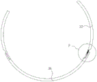
FIG. 13 is a schematic view of the filter plate and arc-shaped limiting plate structure of the present invention;
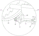
fig. 14 is a schematic view of the structure at F in fig. 13.
In the drawings, the components represented by the respective reference numerals are listed below:
the crushing box comprises a crushing box 1, a feeding plate 2, a U-shaped connecting block 3, a mounting disc 4, a crushing roller 5, a first motor 6, a sieve plate 7, a ring groove 8, a sliding shaft 9, a scraping plate 10, an arc-shaped baffle plate 11, a first outer toothed ring 12, an annular frame 13, an L-shaped connecting block 14, a second motor 15, a first gear 16, a first baffle plate 17, a second baffle plate 18, a torsion spring 19, a second gear 20, an arc-shaped rack 21, an arc-shaped sliding rod 22, an arc-shaped spring 23, an L-shaped sliding rail 24, an L-shaped sliding plate 25, a through groove 26, an air spring 27, an arc-shaped guide block 28, a first guide block 29, a rectangular connecting block 30, a first rotating rod 31, a third gear 32, a second outer toothed ring 33, a stirring rod 34, a first sliding groove 35, a filtering plate 36, an arc-shaped limiting plate 37, a second sliding groove 38, an arc-shaped sliding plate 39, a first spring 40, a first, An outer grinding roller 45, a first connecting plate 46, a third motor 47 and an inner grinding roller 48.
Detailed Description
The technical solutions in the embodiments of the present invention will be clearly and completely described below with reference to the drawings in the embodiments of the present invention, and it is obvious that the described embodiments are only a part of the embodiments of the present invention, and not all of the embodiments. All other embodiments, which can be derived by a person skilled in the art from the embodiments given herein without making any creative effort, shall fall within the protection scope of the present invention.
Referring to fig. 1-14, the present invention provides a technical solution: a waste thermosetting plastic regeneration device comprises a crushing box 1, wherein a feeding plate 2 is fixedly connected to the left side of the crushing box 1, mounting discs 4 are fixedly connected to the front side wall and the rear side wall of the crushing box 1 through a plurality of U-shaped connecting blocks 3, the front mounting disc 4 and the rear mounting disc 4 are jointly and rotatably connected with three crushing rollers 5, the rear ends of the three crushing rollers 5 penetrate through the rear mounting disc 4 and are fixedly connected with first motors 6, the three first motors 6 are fixedly connected to the rear side wall of the mounting disc 4 at the rear side, a sieve plate 7 is connected to the inner side wall of the crushing box 1, sieve holes are formed in the positions, close to the bottom, of the sieve plate 7, an annular groove 8 is formed between the mounting discs 4 and the crushing box 1, a sliding shaft 9 is jointly and slidably connected to the inner side walls of the front annular groove 8 and the rear annular groove, a scraping plate 10 is fixedly connected to the outer side wall of the, the front end and the rear end of the sliding shaft 9 are fixedly connected with a first outer toothed ring 12, the outer side wall of the mounting disc 4 is fixedly connected with an annular frame 13, the first outer toothed ring 12 is rotatably connected on the outer side wall of the annular frame 13, the outer sides of the front mounting disc 4 and the rear mounting disc 4 are fixedly connected with a second motor 15 through an L-shaped connecting block 14, the output shaft of the second motor 15 is fixedly connected with a first gear 16, the first gear 16 is meshed with the outer teeth of the first outer toothed ring 12, the right side wall inside the crushing box 1 is rotatably connected with a first baffle 17, the bottom of the first baffle 17 is contacted with the inner side wall of the sieve plate 7, the inner end of the first baffle 17 is contacted with the outer side wall of the arc baffle 11, the front side wall and the rear side wall of the first baffle 17 are connected with a rotating mechanism for driving the first baffle 17 to overturn, the left side wall inside the crushing box 1 is rotatably connected with a second baffle 18, the outer side wall of the first outer toothed ring 12 is connected, the inner side of the crushing box 1 is connected with a grinding mechanism for grinding the crushed plastic;
the rotating mechanism comprises two torsion springs 19, the inner ends of the two torsion springs 19 are fixedly connected to the rotating connection position of the front side wall and the rear side wall of the first baffle plate 17, the outer ends of the two torsion springs 19 are fixedly connected to the inner side wall of the crushing box 1, the rear end of the sliding shaft 9 of the first baffle plate 17 penetrates through the crushing box 1 and is fixedly connected with a second gear 20, the second gear 20 is located on the rear side of the first outer gear ring 12, an arc-shaped rack 21 is fixedly connected to the rear side wall of the first outer gear ring 12, the arc-shaped rack 21 is located right behind the sliding shaft 9, and the arc-shaped rack 21 is used for driving the second gear;
the opening and closing mechanism comprises two arc-shaped slide rods 22, the rotating centers of the two arc-shaped slide rods 22 are the rotating axes of the second baffle 18, the inner ends of the arc-shaped slide rods 22 are fixedly connected to the bottom of the second baffle 18, the outer ends of the two arc-shaped slide rods 22 penetrate through the crushing box 1 and are in sliding connection with the crushing box, arc-shaped springs 23 are sleeved on the two arc-shaped slide rods 22, an L-shaped slide rail 24 is fixedly connected to the left side wall of the crushing box 1, an L-shaped slide plate 25 is slidably connected to the L-shaped slide rail 24, two through grooves 26 for the two arc-shaped slide rods 22 to pass through are formed in the L-shaped slide plate 25, air springs 27 are fixedly connected to the inner side wall of the L-shaped slide plate 25, the front ends of the air springs 27 are fixedly connected to the rear side wall of the crushing box 1, arc-shaped guide blocks 28 are fixedly connected to the rear end of, the first guide block 29 is used for pressing the arc-shaped guide block 28;
when the thermosetting plastic crusher works, after the thermosetting plastic is crushed by the crushing mechanism in the prior art, the crushed thermosetting plastic can enter the grinding mechanism to be ground after being screened by the filter screen, the crushed thermosetting plastic can not be completely crushed into fragments which can pass through the filter screen after being filtered once, and the thermosetting plastic fragments which can not pass through the filter screen stop at the top of the filter screen, so that the subsequent screening of the filter screen on the thermosetting fragments can be influenced, and the thermosetting plastic fragments which stop at the top of the filter screen can not be completely recycled, the invention provides a technical scheme for solving the problems, when the thermosetting plastic crusher is used, the crushing box 1 is fixedly connected at a stable working position, then the three first motors 6 are started to drive the three crushing rollers 5 to rotate, and the thermosetting plastic which needs to be recycled is added into the crushing box 1 from the feeding plate 2, the three crushing rollers 5 crush the entering thermosetting plastic, after the thermosetting plastic to be recovered is crushed, the thermosetting plastic particles which are crushed to meet a certain particle size fall into the grinding mechanism from the sieve holes of the sieve plate 7 to be ground, and part of large thermosetting plastic particles and smaller thermosetting plastic particles which are blocked and cannot directly fall are stopped at the top of the sieve plate 7 and cannot be completely processed and recovered, at the moment, two second motors 15 are started, the second motors 15 drive two first gears 16 to rotate, the first gears 16 drive first outer toothed rings 12 which are meshed with the first gears to rotate in an annular frame 13, the front and rear first outer toothed rings 12 drive sliding shafts 9 which are fixed with the first outer toothed rings to move along the tense circumference of the ring grooves 8, the sliding shafts 9 drive scraping plates 10 to scrape along the inner side wall of the sieve plate 7, so as to scrape the thermosetting plastic positioned at the top of the sieve plate 7, meanwhile, when the accumulated smaller thermosetting plastic particles are driven to fall from the sieve pores, the scraping plate 10 drives the plastic particles which are not completely crushed to meet the grinding condition to move upwards, meanwhile, the plastic particles of the scraping plate 10 are simultaneously limited by the arc-shaped baffle plate 11 and the inner wall of the sieve plate 7, the problem that the plastic particles directly fall from the scraping plate 10 when the scraping plate 10 drives the plastic particles is avoided, when the scraping plate 10 is driven to move to the top of the crushing roller 5, the first baffle plate 17 is always attached to the outer side wall of the arc-shaped baffle plate 11 under the action of the torsion spring 19, when the thermosetting plastic is crushed, the thermosetting plastic is ensured not to directly fall from between the arc-shaped baffle plate 11 and the sieve plate 7, the thermosetting plastic can be crushed, when the first outer toothed ring 12 rotates, the arc-shaped rack 21 fixedly connected with the first outer toothed ring 12 is driven to rotate together, and after the arc-shaped rack 21 is meshed with the second gear 20, the arc-shaped rack 21 continues to rotate to drive the second gear 20 to rotate, the second gear 20 drives the first baffle 17 to turn upwards to open, then the scraping plate 10 moves to pass through the opened first baffle 17 directly, the phenomenon that the plastic particles fall off due to the contact of the first baffle 17 and the plastic particles at the top of the scraping plate 10 is avoided, after the scraping plate 10 passes through the first baffle 17, the arc-shaped rack 21 is separated from the second gear 20, the first baffle 17 turns downwards to reset under the action of the two torsion springs 19, the first baffle 17 falls on the top of the sieve plate 7 again, meanwhile, the scraping plate 10 is separated from the arc-shaped baffle 11 at the right side, the plastic fragments at the top of the scraping plate 10 fall off from the inner side of the scraping plate 10 and fall on the inner sides of the three crushing rollers 5 again to be crushed, the plastic fragments with the crushing degree not meeting the granularity are crushed again, and then fall into the grinding mechanism from sieve holes of the sieve plate, the rectangular scraping plate 10 is driven to rotate anticlockwise continuously, the L-shaped sliding plate 25 is tensioned by the air spring 27, the through groove 26 in the L-shaped sliding plate 25 and the arc-shaped sliding rod 22 have front-back position deviation, namely the L-shaped sliding plate 25 blocks the arc-shaped sliding rod 22, the arc-shaped sliding rod 22 limits the second baffle 18 at the top of the left arc-shaped baffle 11 to block thermosetting plastics, when the scraping plate 10 is to be moved to the position of the second baffle 18, the first guide block 29 driven by the first outer toothed ring 12 acts on and extrudes the arc-shaped guide block 28 before the arc-shaped guide block 28 acts, the L-shaped sliding plate 25 is meshed and slides backwards along the L-shaped sliding rail 24, the through groove 26 in the L-shaped sliding plate 25 is butted with the arc-shaped sliding rod 22, then the scraping plate 10 is contacted with the second baffle 18 to extrude the second baffle 18, so that the second baffle 18 is overturned downwards, the arc-shaped sliding rod 22 slides out of the through groove 26 to compress the, the second baffle 18 is reset under the action of the arc spring 23, the arc slide rod 22 is reset, the first guide block 29 is separated from the arc guide block 28, the L-shaped sliding plate 25 moves forwards under the action of the air spring 27, so that the arc slide rod 22 is blocked again by the through groove 26 on the L-shaped sliding plate 25, the second baffle 18 is prevented from overturning during the thermosetting plastic crushing, the scraping plate 10 is driven to continuously scrape the plastic fragments falling on the top of the sieve plate 7 under the continuous rotation of the first outer toothed ring 12 until the tops of the three crushing rollers 5 are crushed again until the plastic fragments are crushed into plastic fragments which can enter the grinding mechanism through the sieve plate 7, the motor is turned off, the recycling work of the thermosetting plastic is completed once, and the thermosetting plastic fragments with insufficient crushing granularity are scraped by the scraping plate 10 during the continuous rotation of the crushing box 1 every time, reuse sieve 7 and cowl 11 cooperation scraping flitch 10 and block the plastic granules who scrapes, guarantee that the plastic fragments who scrape can fall from the top of crushing roller 5, when scraping flitch 10 and moving through first baffle 17 and second baffle 18, cooperation slewing mechanism and mechanism of opening and shutting open first baffle 17 and second baffle 18 in advance, make scraping flitch 10 can realize the circular motion, carry out continuous scraping action, guarantee not thoroughly by broken complete plastic granules by a lot of breakage, make thermosetting plastics can be totally by recycle.
As a further scheme of the invention, a first rotating rod 31 is rotatably connected to the right side wall of the scraping plate 10 through two rectangular connecting blocks 30, the front end of the first rotating rod 31 penetrates through the front rectangular connecting block 30 and is fixedly connected with a third gear 32, a second external gear ring 33 is fixedly connected to the front side wall inside the crushing box 1, the third gear 32 is meshed with the second external gear ring 33, and a plurality of linear array stirring rods 34 are fixedly connected to the outer surface of the first rotating rod 31; during operation, as part of plastic particles which fall on the top of the sieve plate 7 and meet the grinding particle size may be blocked by larger plastic particles and cannot directly fall into the middle of the grinding mechanism for grinding, when the scraping plate 10 rotates, the first rotating rod 31 is driven by the rectangular connecting block 30 to synchronously perform circular motion, the third gear 32 at the front end of the first rotating rod 31 is meshed with the second outer toothed ring 33, so that the third gear 32 rotates, the third gear 32 drives the first rotating rod 31 to rotate, the stirring rod 34 fixedly connected to the outer surface of the first rotating rod 31 rotates, the plastic particles scraped by the scraping plate 10 are stirred, smaller plastic fragments and larger plastic fragments form movement, the smaller plastic fragments can directly fall from sieve holes of the sieve plate 7 and are ground by the grinding mechanism, and the phenomenon that the smaller plastic fragments and the larger plastic fragments are scraped together for repeated processing is avoided, and the condition that the sieve pore of sieve 7 is plugged up to the plastic chip at sieve 7 top has been avoided appearing to realize utilizing stirring rod 34 to stir accumulational crushed aggregates piece when scraping flitch 10 and scraping the plastic chip at every turn, make the plastic chip of less granule can directly fall down from the sieve pore of sieve 7, avoid reprocessed problem.
As a further scheme of the invention, the sieve plate 7 is provided with a filter plate 36 and two arc-shaped limit plates 37, the butt joint end parts of the arc-shaped limit plates 37 and the filter plate 36 are respectively provided with a first sliding chute 35 for butt joint, the two arc-shaped limit plates 37 are fixedly connected on the inner side wall of the crushing box 1, the filter plate 36 is slidably connected in the two arc-shaped limit plates 37, the bottom of the right arc-shaped limit plate 37 is provided with a second sliding chute 38, the inner part of the second sliding chute 38 is respectively and slidably connected with an arc-shaped sliding plate 39, the bottom end of the arc-shaped sliding plate 39 is contacted with the filter plate 36, the top end of the arc-shaped sliding plate 39 is fixedly connected with two first springs 40, the top ends of the two first springs 40 are respectively and fixedly connected on the bottom surface of the second sliding chute 38, the top part of the filter plate 36 is fixedly connected with two first, the first friction block 41 and the second friction block 42 are both rubber blocks; in operation, as the broken thermosetting plastic fragments are accumulated on the top of the screen plate 7, the screen plate 7 may be blocked from screening subsequent plastic fragments, by dividing the screen plate 7 into two parts, when the scraping plate 10 is driven to rotate and scrape the materials, the scraping plate 10 drives the second friction block 42 to rotate together through the first rotating rod 31, when the rotating belt of the second friction block 42 contacts with the first friction block 41, the first friction block 41 and the filter plate 36 are driven to slide along the first chute 35, the filter plate 36 presses the arc-shaped sliding plate 39, so that the arc-shaped sliding plate 39 slides into the second chute 38, when the top end of the filter plate 36 contacts with the bottom of the first chute 35, the second friction block 42 continues to move upwards, the second friction block 42 is separated from the first friction block 41, the arc-shaped sliding plate 39 is ejected under the action of the first spring 40, the filter plate 36 slides to the left under the gravity and the extrusion of the arc-shaped sliding plate 39, therefore, when the plastic fragment piece is scraped by the scraping plate 10, the filtering plate 36 is driven to swing back and forth, so that the plastic fragment at the top of the filtering plate 36 is dispersed, the fragment flow is promoted, and the plastic fragment meeting the particle size requirement directly falls from the filtering plate 36 to be ground.
As a further scheme of the invention, the grinding mechanism comprises a guide shell 43, the guide shell 43 is fixedly connected to the inner side wall of the crushing box 1, the guide shell 43 is positioned at the bottom of the sieve plate 7, a rectangular connecting plate 44 is fixedly connected to the inner side wall of the crushing box 1, an outer grinding roller 45 is fixedly connected to the inner side wall of the rectangular connecting plate 44, a third motor 47 is fixedly connected to the inner side wall of the crushing box 1 through a first connecting plate 46, and the top end of an output shaft of the third motor 47 is fixedly connected with an inner grinding roller 48 positioned inside the outer grinding roller 45; during operation, because the broken thermosetting plastics piece to certain granularity need be just reaching the degree of using through grinding, through starting third motor 47, the interior grinding roller that drives rotates, and the plastic granules after the breakage falls into interior grinding roller and grinds between the outer grinding roller, and the plastic granules after the grinding directly falls down from between two grinding rollers, accomplishes a thermosetting plastics and handles.
A regeneration process of waste thermosetting plastic regeneration equipment comprises the following specific steps:
the method comprises the following steps: firstly, fixedly connecting a crushing box 1 at a stable working position;
step two: then, adding the thermosetting plastics to be recycled into the crushing box 1 from the feeding plate 2;
step three: after the crushing is finished, starting the two second motors 15 to drive the scraping plates 10 to move, scraping the plastic fragments falling on the top of the sieve plate 7 between the crushing rollers 5, and crushing again;
step four: after the plastic fragments are scraped and brought up by the scraping plate 10 for multiple times, the completely crushed thermosetting plastic fragments fall into the grinding mechanism for grinding;
step five: finally, the granulated thermoset is collected.
The working principle is as follows: when the invention is used, a crushing box 1 is fixedly connected at a stable working position, then three first motors 6 are started to drive three crushing rollers 5 to rotate, thermosetting plastic to be recovered is added into the crushing box 1 from a feed plate 2, the three crushing rollers 5 crush the entering thermosetting plastic, after the thermosetting plastic to be recovered is crushed, thermosetting plastic particles crushed to a certain granularity fall into a grinding mechanism from sieve holes of a sieve plate 7 to be ground, and part of larger thermosetting plastic particles and smaller thermosetting plastic particles which are blocked and cannot directly fall down stay at the top of the sieve plate 7 and cannot be thoroughly treated and recovered, at the moment, two second motors 15 are started, the second motors 15 drive two first gears 16 to rotate, the first gears 16 drive first outer toothed rings 12 meshed with the first gears to rotate in an annular frame 13, the front and the back first external toothed rings 12 drive the sliding shaft 9 fixed with the sliding shaft to do tense circular motion along the annular groove 8, the sliding shaft 9 drives the scraping plate 10 to scrape along the inner side wall of the sieve plate 7, the thermosetting plastic at the top of the sieve plate 7 is scraped, meanwhile, when the piled small thermosetting plastic particles are driven, the piled small thermosetting plastic particles fall down from the sieve holes, the scraping plate 10 drives the plastic particles which are not completely crushed to meet the grinding condition to move upwards, simultaneously, the plastic particles of the scraping plate 10 are limited by the arc-shaped baffle plate 11 and the inner wall of the sieve plate 7 simultaneously, the problem that the plastic particles directly fall down from the scraping plate 10 when the scraping plate 10 drives the plastic particles is avoided, when the scraping plate 10 is driven to move to the top of the crushing roller 5, the first baffle plate 17 is always attached to the outer side wall of the arc-shaped baffle plate 11 under the action of the torsion spring 19, and when the thermosetting plastic is crushed, the thermosetting plastic can not directly fall down from the space between the arc-shaped baffle plate 11 and the sieve plate 7, the thermosetting plastic can be broken, the arc-shaped rack 21 fixedly connected with the first outer toothed ring 12 is driven to rotate simultaneously when the first outer toothed ring 12 rotates, after the arc-shaped rack 21 is meshed with the second gear 20, the arc-shaped rack 21 continues to rotate to drive the second gear 20 to rotate, the second gear 20 drives the first baffle plate 17 to turn upwards and open, then the scraping plate 10 moves to directly pass through the opened first baffle plate 17, the plastic particles at the top of the scraping plate 10 are prevented from contacting with the first baffle plate 17, the plastic particles fall down, after the scraping plate 10 passes through the first baffle plate 17, the arc-shaped rack 21 is separated from the second gear 20, the first baffle plate 17 turns downwards under the action of the two torsion springs 19 to reset, the first baffle plate 17 falls down at the top of the sieve plate 7 again, and simultaneously, the scraping plate 10 is separated from the arc-shaped, the plastic fragments at the top of the scraping plate 10 fall from the inner side of the scraping plate 10 and fall on the inner sides of the three crushing rollers 5 again for crushing, the plastic fragments with the crushing degree not meeting the granularity are crushed again, then the plastic fragments fall into the grinding mechanism from the sieve pores of the sieve plate 7 for grinding, the rectangular scraping plate 10 is driven to continue to rotate anticlockwise, the L-shaped sliding plate 25 is tensioned by the air spring 27, the through groove 26 in the L-shaped sliding plate 25 and the arc-shaped sliding rod 22 have front-back position deviation, namely the L-shaped sliding plate 25 blocks the arc-shaped sliding rod 22, the arc-shaped sliding rod 22 limits the second baffle plate 18 at the top of the arc-shaped baffle plate 11 at the left side to block thermosetting plastics, when the scraping plate 10 is to be moved to the position of the second baffle plate 18, the first guide block 29 driven by the first outer toothed ring 12 acts on and extrudes the arc-shaped guide block 28 before the arc-shaped guide block 28, the through groove 26 on the L-shaped sliding plate 25 is butted with the arc-shaped sliding rod 22, then the scraping plate 10 touches the second baffle 18 to extrude the second baffle 18, the second baffle 18 is overturned downwards, the arc-shaped sliding rod 22 slides out of the through groove 26 to compress the arc-shaped spring 23, after the scraping plate 10 passes through the second baffle 18, the second baffle 18 is reset under the action of the arc-shaped spring 23, the arc-shaped sliding rod 22 is reset, the first guide block 29 is separated from the arc-shaped guide block 28, the L-shaped sliding plate 25 moves forwards under the action of the air spring 27 to enable the through groove 26 on the L-shaped sliding plate 25 to block the arc-shaped sliding rod 22 again, the second baffle 18 is prevented from overturning during the breaking of thermosetting plastics, the scraping plate 10 is driven under the continuous rotation of the first outer toothed ring 12 to scrape the plastic fragments falling on the top of the sieve plate 7 continuously to the tops of the three breaking rollers 5 for breaking again until the plastic fragments are broken into plastic fragments which can enter the grinding mechanism, and (5) turning off the motor to finish the recovery work of the thermosetting plastic once.
In the description herein, references to the description of "one embodiment," "an example," "a specific example" or the like are intended to mean that a particular feature, structure, material, or characteristic described in connection with the embodiment or example is included in at least one embodiment or example of the invention. In this specification, the schematic representations of the terms used above do not necessarily refer to the same embodiment or example. Furthermore, the particular features, structures, materials, or characteristics described may be combined in any suitable manner in any one or more embodiments or examples.
The preferred embodiments of the invention disclosed above are intended to be illustrative only. The preferred embodiments are not intended to be exhaustive or to limit the invention to the precise embodiments disclosed. Obviously, many modifications and variations are possible in light of the above teaching. The embodiments were chosen and described in order to best explain the principles of the invention and the practical application, to thereby enable others skilled in the art to best utilize the invention. The invention is limited only by the claims and their full scope and equivalents.