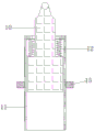
Be used for energy storage flywheel to prevent blockking up perforating device
Technical Field
The invention relates to the technical field of flywheel processing, in particular to an anti-blocking punching device for an energy storage flywheel.
Background
The flywheel energy storage means an energy storage mode that a motor drives a flywheel to rotate at a high speed and the flywheel drives a generator to generate electricity when needed.
In the course of working at energy storage flywheel, often need punch on the flywheel in order to satisfy the production requirement, current perforating device for flywheel causes the phenomenon that the position of punching is blockked up by the blanking that punches easily, and causes the flywheel to punch the position when current device fixes the flywheel easily and warp inhomogeneous all around to lead to the inhomogeneous problem in hole of punching.
Disclosure of Invention
Technical problem to be solved
Aiming at the defects of the prior art, the invention provides the anti-blocking punching device for the energy storage flywheel, which has the advantages of preventing the punching device from being blocked and enabling holes to be formed uniformly, and solves the problems that the existing device cannot prevent the punching device from being blocked and cannot enable the holes to be formed uniformly.
(II) technical scheme
In order to realize the purposes of preventing the punching device from being blocked and enabling the holes to be formed uniformly, the invention provides the following technical scheme: a blocking-proof punching device for an energy storage flywheel comprises a bottom plate, wherein a support is fixedly connected to the bottom plate, a first support column is fixedly connected to the left of the top of the support, a pressure rod is hinged to the first support column, a first spring is fixedly connected between the pressure rod and the support, a second support column is fixedly connected to the right of the top of the support, a cam is connected to the second support column, a first driving lever is fixedly connected to the left of the cam, a second driving lever is fixedly connected to the right of the cam, a support column is hinged to the middle of the pressure rod, an opening cylinder is sleeved on the outer ring of the support column, a second spring is arranged between the opening cylinder and the support column, a sleeve is arranged outside the opening cylinder, a fixed rod is fixedly connected to the left of the sleeve, a convex block is fixedly connected to the outer wall of the opening cylinder, a stop block is fixedly connected to the inner wall of the, the lower end of the third spring is fixedly connected with a pressing block, the lower part of the support is fixedly connected with an object bearing plate, and a blanking hole is formed in the object bearing plate.
Preferably, the cam is driven by a motor, and automatic operation of the device can be realized.
Preferably, the upper portion of the stay is provided with a step shape, so that the second spring can be conveniently installed.
Preferably, the lower end of the perforating cylinder is provided with a cutting edge, so that the perforating cylinder can perforate the flywheel conveniently.
Preferably, the cross section of the pressing block is circular, so that the chips around the opening on the flywheel are uniformly stressed.
Preferably, the diameter of the blanking hole is larger than that of the perforated cylinder, so that flywheel blanking in the perforated cylinder can fall from the blanking hole.
(III) advantageous effects
Compared with the prior art, the invention provides an anti-blocking punching device for an energy storage flywheel, which has the following beneficial effects:
1. this be used for energy storage flywheel to prevent blockking up perforating device, through being provided with the cam, and the part is provided with first driving lever and second driving lever respectively about the cam, just can realize when the cam rotates, first driving lever contacts with the depression bar earlier and pushes down the depression bar, thereby make trompil section of thick bamboo press accomplish the blanking of punching a hole in advancing the flywheel, when the cam continues to rotate, first driving lever can break away from with the depression bar, the depression bar normal position is replied to this moment, when the cam rotates to second driving lever and depression bar contact and pushes down the depression bar, then can extrude the piece blanking in the trompil section of thick bamboo, in order to prevent to block up.
2. This be used for energy storage flywheel to prevent blockking up perforating device through being provided with first driving lever and second driving lever, when the second driving lever pushed down the depression bar, the distance of depression bar downstream was bigger for the distance when first driving lever pressed down with it contact, and the lug on the trompil section of thick bamboo outer wall can be blocked by the dog of cover inner wall this moment to the messenger props the post for a trompil section of thick bamboo downstream, props out the piece blanking of plugging up in the trompil section of thick bamboo and influences trompil work next time in order to prevent to block up.
3. This be used for energy storage flywheel to prevent blockking up perforating device is provided with the briquetting through the lower part at a trompil section of thick bamboo, can make a trompil section of thick bamboo move down to push down the flywheel before carrying out the trompil in order to prevent that the flywheel from sliding to guarantee the stability of trompil work and go on, through setting up the briquetting into the ring form, can make the flywheel have the same deformation under the effect of briquetting by trompil position piece all around, make the trompil end back flywheel resume the round hole of opening after the deformation still even.
Drawings
FIG. 1 is a front cross-sectional view of the present invention;
FIG. 2 is a schematic front view of the cam of the present invention;
FIG. 3 is a front cross-sectional view of the perforated cartridge of the present invention;
fig. 4 is a cross-sectional view of the sleeve of the present invention.
In the figure: 1-bottom plate, 2-bracket, 3-first support, 4-compression bar, 5-first spring, 6-second support, 7-cam, 8-first deflector rod, 9-second deflector rod, 10-support column, 11-perforated cylinder, 12-second spring, 13-sleeve, 14-fixed rod, 15-lug, 16-stop block, 17-fixed block, 18-third spring, 19-press block, 20-object bearing plate and 21-blanking hole.
Detailed Description
The technical solutions in the embodiments of the present invention will be clearly and completely described below with reference to the drawings in the embodiments of the present invention, and it is obvious that the described embodiments are only a part of the embodiments of the present invention, and not all of the embodiments. All other embodiments, which can be derived by a person skilled in the art from the embodiments given herein without making any creative effort, shall fall within the protection scope of the present invention.
Referring to fig. 1-4, an anti-clogging punching device for an energy storage flywheel comprises a base plate 1, a support 2 is fixedly connected to the base plate 1, a first support 3 is fixedly connected to the left of the top of the support 2, a press rod 4 is hinged to the first support 3, a first spring 5 is fixedly connected between the press rod 4 and the support 2, the first spring is arranged to facilitate the return of the press rod 4, a second support 6 is fixedly connected to the right of the top of the support 2, a cam 7 is connected to the second support 6, the cam 7 is driven by a motor to realize the automatic operation of the device, a first deflector rod 8 is fixedly connected to the left of the cam 7, a second deflector rod 9 is fixedly connected to the right of the cam 7, a support column 10 is hinged to the middle of the press rod 4, an open-hole cylinder 11 is sleeved on the outer ring of the support column 10, a second spring 12 is arranged between the open-hole cylinder 11 and the support column 10, so as to facilitate the installation of the second spring 12, the lower end of the perforated cylinder 11 is provided with a cutting edge, which is beneficial for the perforated cylinder 11 to perforate the flywheel, the outer part of the perforated cylinder 11 is provided with a sleeve 13, the left side of the sleeve 13 is fixedly connected with a fixed rod 14, the outer wall of the perforated cylinder 11 is fixedly connected with a lug 15, the inner wall of the sleeve 13 is fixedly connected with a stop block 16, the lug 15 and the stop block 16 are matched to play a role in stopping displacement of the perforated cylinder 11, the lower part of the perforated cylinder 11 is fixedly connected with a fixed block 17, the lower end of the fixed block 17 is fixedly connected with a third spring 18, the lower end of the third spring 18 is fixedly connected with a, the scraps around the opening on the flywheel can be evenly stressed, the lower part of the bracket 2 is fixedly connected with an object bearing plate 20, the object bearing plate 20 is provided with a blanking hole 21, and the diameter of the blanking hole 21 is larger than that of the perforated cylinder 11, so that the flywheel blanking in the perforated cylinder 11 can fall from the blanking hole 21.
The working principle is as follows: the flywheel is placed on an object bearing plate 20, a motor is started to drive a cam 7 to rotate, when a first deflector rod 8 on the cam 7 is in contact with a pressure rod 4 to press the pressure rod 4 downwards, a hole opening cylinder 11 moves downwards to open a hole in the flywheel, a pressing block 19 is arranged at the lower part of the hole opening cylinder 11, the hole opening cylinder 11 can move downwards to press the flywheel before the flywheel is opened to prevent the flywheel from sliding, so that the stable operation of the hole opening is ensured, the pressing block 19 is arranged into a circular ring shape, the flywheel can be deformed equally by scraps around the hole opening part under the action of the pressing block 19, circular holes formed after the flywheel is deformed again are still uniform after the hole opening is finished, when the hole opening cylinder 11 is pressed into the flywheel to complete punching and blanking, the cam 7 can continue to rotate, the first deflector rod 8 can be separated from the pressure rod 4, at the moment, the pressure rod 4 returns to the original position, when the cam 7 rotates to a second deflector rod 9 to be in contact with, the downward movement distance of the pressure lever 4 is larger than the movement distance when the first shift lever 8 is contacted with the pressure lever and pressed downwards, and at the moment, the bump 15 on the outer wall of the perforated cylinder 11 is blocked by the stop 16 on the inner wall of the sleeve 13, so that the support column 10 moves downwards relative to the perforated cylinder 11, and scraps blocked in the perforated cylinder 11 are supported out of the blanking hole 21 in the object bearing plate 20 and fall off, so that the blocking is prevented from influencing the next tapping work.
Although embodiments of the present invention have been shown and described, it will be appreciated by those skilled in the art that changes, modifications, substitutions and alterations can be made in these embodiments without departing from the principles and spirit of the invention, the scope of which is defined in the appended claims and their equivalents.