CN112796505A - Scaffold pre-buried sliding groove type wall connecting piece and construction method thereof - Google Patents

Scaffold pre-buried sliding groove type wall connecting piece and construction method thereof Download PDF

Info

Publication number
CN112796505A
CN112796505A CN202110171741.6A CN202110171741A CN112796505A CN 112796505 A CN112796505 A CN 112796505A CN 202110171741 A CN202110171741 A CN 202110171741A CN 112796505 A CN112796505 A CN 112796505A
Authority
CN
China
Prior art keywords
embedded
connecting wall
wall
chute
piece
Prior art date
Legal status (The legal status is an assumption and is not a legal conclusion. Google has not performed a legal analysis and makes no representation as to the accuracy of the status listed.)
Pending
Application number
CN202110171741.6A
Other languages
Chinese (zh)
Inventor
蔡敏
尹自林
钟凌宇
陈维超
官升
王俊
黄鹤
曾庆国
Current Assignee (The listed assignees may be inaccurate. Google has not performed a legal analysis and makes no representation or warranty as to the accuracy of the list.)
Hunan Construction Engineering Group Co Ltd
Original Assignee
Hunan Construction Engineering Group Co Ltd
Priority date (The priority date is an assumption and is not a legal conclusion. Google has not performed a legal analysis and makes no representation as to the accuracy of the date listed.)
Filing date
Publication date
Application filed by Hunan Construction Engineering Group Co Ltd filed Critical Hunan Construction Engineering Group Co Ltd
Priority to CN202110171741.6A priority Critical patent/CN112796505A/en
Publication of CN112796505A publication Critical patent/CN112796505A/en
Pending legal-status Critical Current

Links

Images

Classifications

    • E—FIXED CONSTRUCTIONS
    • E04—BUILDING
    • E04G—SCAFFOLDING; FORMS; SHUTTERING; BUILDING IMPLEMENTS OR AIDS, OR THEIR USE; HANDLING BUILDING MATERIALS ON THE SITE; REPAIRING, BREAKING-UP OR OTHER WORK ON EXISTING BUILDINGS
    • E04G5/00—Component parts or accessories for scaffolds
    • E04G5/04—Means for fastening, supporting, or bracing scaffolds on or against building constructions
    • E04G5/046—Means for fastening, supporting, or bracing scaffolds on or against building constructions for fastening scaffoldings on walls

Landscapes

  • Engineering & Computer Science (AREA)
  • Architecture (AREA)
  • Mechanical Engineering (AREA)
  • Civil Engineering (AREA)
  • Structural Engineering (AREA)
  • Joining Of Building Structures In Genera (AREA)

Abstract

本发明提供了一种脚手架预埋滑槽式连墙件及其施工方法,所述连墙件包括预埋件和连墙杆,所述预埋件的背面设置有锚固钢筋,在所述预埋件的正面沿竖向设置有两道相对设置的滑槽;所述连墙杆的一端固定有连接板,在所述连接底板上位于连墙杆的两侧分别开设有通孔,且在所述连接底板上与通孔对应的位置固定有螺母,所述螺母上安装有螺栓;使用时连接板的两侧分别设置在两道滑槽内,且螺栓的尾部抵接在预埋件上。本发明采用连墙杆、螺栓等可周转使用材料,节约了工程成本,达到了降本增效的目的,且避免了墙体洞口封堵不严造成渗漏的现象发生。

Figure 202110171741

The invention provides a scaffold pre-embedded chute-type connecting wall piece and a construction method thereof. The wall connecting piece comprises a pre-embedded piece and a connecting wall rod. An anchoring steel bar is arranged on the back of the embedded piece. The front side of the embedded part is vertically provided with two oppositely arranged chutes; one end of the connecting wall rod is fixed with a connecting plate, and through holes are respectively opened on both sides of the connecting wall rod on the connecting base plate, and the A nut is fixed on the connecting base plate at a position corresponding to the through hole, and a bolt is installed on the nut; when in use, both sides of the connecting plate are respectively arranged in two chutes, and the tail of the bolt abuts on the embedded part . The invention adopts revolvable materials such as connecting wall rods, bolts, etc., which saves engineering costs, achieves the purpose of reducing costs and increasing efficiency, and avoids the phenomenon of leakage caused by poor sealing of wall openings.

Figure 202110171741

Description

Scaffold pre-buried sliding groove type wall connecting piece and construction method thereof
Technical Field
The invention relates to a scaffold pre-buried sliding groove type wall connecting piece and a construction method thereof, and belongs to the field of house building construction.
Background
At present, in the process of building external scaffolds on a construction site, the common wall connecting piece is prepared by the following steps: a vertical short steel pipe is pre-buried in the slab before concrete pouring, and after the concrete pouring is finished, two ends of a cross rod are respectively connected with the pre-buried vertical steel pipe and the outer scaffold. The method has high cost, is troublesome to disassemble and cannot be circulated, and a hole reserved behind the masonry body must be plugged, so that the hidden danger of water seepage is caused.
Disclosure of Invention
The invention aims to provide a scaffold pre-buried sliding groove type wall connecting piece to solve the problems that pre-buried steel pipes cannot be circulated, a hole reserved behind a masonry needs to be plugged and the like.
In order to achieve the purpose, the invention adopts the technical scheme that: a scaffold pre-buried sliding groove type wall connecting piece comprises a pre-buried piece and a wall connecting rod, wherein anchoring steel bars are arranged on the back surface of the pre-buried piece, and two sliding grooves which are oppositely arranged are vertically arranged on the front surface of the pre-buried piece; a connecting plate is fixed at one end of the wall connecting rod, through holes are respectively formed in the connecting bottom plate and positioned on two sides of the wall connecting rod, nuts are fixed on the connecting bottom plate and correspond to the through holes, and bolts are mounted on the nuts; when the connecting plate is used, two sides of the connecting plate are respectively arranged in the two sliding grooves, and the tail part of the bolt is abutted against the embedded part.
When the wall connecting piece is installed, the connecting bottom plate slides into the sliding groove of the embedded part, then the bolt is screwed down to enable the tail portion of the connecting bottom plate to be abutted against the embedded part, at the moment, the connecting bottom plate is abutted against the inner wall of the sliding groove, therefore, one end of the wall connecting rod is fixed on a building structure, and the other end of the wall connecting rod can be connected with a scaffold. The wall connecting piece adopts the wall connecting rod, the bolt and other recyclable materials, so that the engineering cost is saved, the purposes of cost reduction and efficiency improvement are achieved, and the phenomenon of leakage caused by untight plugging of the wall opening is avoided.
Preferably, the embedded part is a steel plate, two symmetrically arranged L-shaped steel plates are vertically welded on two sides of the front surface of the embedded part, and a sliding groove is formed between each L-shaped steel plate and the embedded part.
Preferably, the length of the embedded part is not less than twice of the length of the connecting bottom plate.
Preferably, the anchoring steel bar is L-shaped, and one end of the horizontal section of the anchoring steel bar is welded with the embedded part.
Preferably, the length of the horizontal section of the anchoring bar is 100mm, and the length of the vertical section is 50 mm.
Preferably, one end of the wall connecting rod is welded at the center of the connecting plate, and the other end of the wall connecting rod is connected with the scaffold in use.
Preferably, when the embedded part is used, the embedded part is embedded in the building structure, and the outer wall of the sliding groove is flush with the outer vertical surface of the building structure.
Based on the same invention concept, the invention also provides a construction method of the scaffold pre-buried sliding groove type wall connecting piece, which specifically comprises the following steps:
firstly, vertically embedding an embedded part into a building structure before an outer wall template is installed, and connecting an anchoring steel bar on the back of the embedded part with a main bar of the building structure;
after the external wall template is disassembled, the connecting bottom plate slides into a sliding groove in the front face of the embedded part, so that the wall connecting rod fixed on the connecting bottom plate is perpendicular to the external vertical face of the building structure;
screwing the bolt into the nut of the connecting bottom plate to enable the tail of the bolt to abut against the embedded part;
and step four, connecting the other end of the wall connecting rod to the scaffold through a fastener.
The invention has the beneficial effects that:
1. the construction method of the wall connecting piece is simple in process, strong in operability and small in construction difficulty. The wall connecting part is divided into an embedded part and a wall connecting rod, the embedded part is a part embedded in the construction process of a building structure, and the wall connecting rod is connected with the embedded part through a connecting bottom plate and is tightly propped through a bolt, so that the wall connecting rod is installed and fixed; when the wall connecting rod is dismantled, the wall connecting rod can slide out only by loosening the bolt, so that the engineering quality can be improved, and the engineering progress is accelerated;
2. compared with the traditional scaffold wall connecting piece, the scaffold wall connecting piece has the advantages that the wall connecting rod, the bolt and the like are adopted, materials can be used in a circulating mode, the engineering cost is saved, the purposes of cost reduction and efficiency improvement are achieved, the risk of leakage caused by untight plugging of the wall opening is avoided, good social benefits are achieved, and the scaffold wall connecting piece is suitable for popularization and use.
Drawings
FIG. 1 is a schematic front view of an embedment of the present invention;
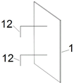
FIG. 2 is a schematic view of the back of an embedment of the present invention;
FIG. 3 is a schematic view of the wall stud of the present invention;
figure 4 is a schematic representation of the invention in use.
Detailed Description
The invention is further illustrated by the following figures and examples.
A scaffold pre-buried chute type wall connecting piece is shown in figures 1-4 and comprises an embedded part 1 and a wall connecting rod 3, wherein anchoring reinforcing steel bars 12 are arranged on the back face of the embedded part 1, and two chutes 11 which are arranged oppositely are vertically arranged on the front face of the embedded part 1. One end of the wall connecting rod 3 is fixed with a connecting plate 2, through holes are respectively arranged on the two sides of the wall connecting rod 3 on the connecting base plate 2, nuts 21 are fixed on the connecting base plate 2 corresponding to the through holes, and bolts 22 are installed on the nuts 21. When the wall connecting rod is used, two sides of the connecting plate 2 are respectively arranged in the two sliding grooves 11, the tail part of the bolt 22 abuts against the embedded part 1, and the free end of the wall connecting rod 3 is connected with the scaffold 5 through the fastener 6.
In this embodiment, the embedded part 1 is vertically embedded in the building structure 4, and the outer wall of the sliding groove 11 is flush with the outer surface of the building structure 4. The length of the embedded part is not less than 2 times of the length of the connecting bottom plate, and the width of the embedded part is not less than the width of the connecting bottom plate. The anchoring steel bar 12 is in an L shape, one end of the horizontal section of the anchoring steel bar is connected with the embedded part 1 in a welding mode, the length of the anchoring steel bar is 100mm, and the length of the vertical section of the anchoring steel bar is 50 mm. The sliding groove 11 is formed by welding and connecting an L-shaped steel plate and the embedded part 1, the length of the sliding groove 11 is not less than that of the connecting bottom plate 2, and the depth of the sliding groove 11 is slightly greater than the thickness of the connecting bottom plate 2. The connecting bottom plate 2 is a square steel plate, and the size of the steel plate is larger than the diameter of the wall connecting rod 3. The specification of the bolt 22 corresponds to that of the nut 21, and after the connecting bottom plate 2 slides into the sliding groove 11, the bolt 22 is screwed tightly and fixed with the embedded part 1.
The construction method of the scaffold pre-buried sliding groove type wall connecting piece in the embodiment specifically comprises the following steps:
the method comprises the following steps: before the outer wall template is installed, vertically embedding an embedded part 1 in a building structure 4, arranging a chute 11 at the lower end of the embedded part 1, and connecting an anchoring reinforcing steel bar 12 with a main bar 41 of the building structure;
step two: after the external wall template is dismantled, one end of the wall connecting rod 3 slides into the embedded part sliding groove 11 through the connecting bottom plate 2 and is vertical to an external vertical surface (a surface vertical to a horizontal plane or a surface with a certain inclination angle relative to the horizontal plane) of the building structure 4;
step three: and screwing two bolts 22 into two nuts 21 of the connecting base plate 2 respectively, so that the tail parts of the bolts 22 are tightly fixed with the embedded part 1.
Step four: the other end of the wall connecting rod 3 is connected with the vertical rod of the scaffold 5 through a fastener 6, so that the construction and installation of the wall connecting piece are realized.

Claims (8)

1.一种脚手架预埋滑槽式连墙件,包括预埋件(1)和连墙杆(3),其特征在于,所述预埋件(1)的背面设置有锚固钢筋(12),在所述预埋件(1)的正面沿竖向设置有两道相对设置的滑槽(11);所述连墙杆(3)的一端固定有连接板(2),在所述连接底板(2)上位于连墙杆(3)的两侧分别开设有通孔,且在所述连接底板(2)上与通孔对应的位置固定有螺母(21),所述螺母(21)上安装有螺栓(22);使用时连接板(2)的两侧分别设置在两道滑槽(11)内,且螺栓(22)的尾部抵接在预埋件(1)上。1. A scaffolding pre-embedded chute type connecting wall piece, comprising embedded piece (1) and connecting wall rod (3), it is characterized in that, the back of described embedded piece (1) is provided with anchoring steel bar (12) , on the front of the embedded part (1) is vertically arranged with two oppositely arranged chutes (11); one end of the connecting wall rod (3) is fixed with a connecting plate (2), which The bottom plate (2) is provided with through holes on both sides of the connecting wall rod (3), respectively, and nuts (21) are fixed on the connecting bottom plate (2) at positions corresponding to the through holes, and the nuts (21) Bolts (22) are installed on the bolts (22); during use, both sides of the connecting plate (2) are respectively arranged in the two chutes (11), and the tails of the bolts (22) abut on the embedded parts (1). 2.如权利要求1所述的脚手架预埋滑槽式连墙件,其特征在于,所述预埋件(1)为钢板,在预埋件(1)的正面两侧沿竖向焊接有两块对称设置的“L”形钢板,每块“L”形钢板与预埋件(1)之间形成一道滑槽(11)。2. The scaffolding pre-embedded chute type connecting wall piece according to claim 1 is characterized in that, the pre-embedded part (1) is a steel plate, and two sides of the front of the pre-embedded part (1) are welded vertically along the vertical direction. Two symmetrically arranged "L"-shaped steel plates, and a chute (11) is formed between each "L"-shaped steel plate and the embedded part (1). 3.如权利要求1所述的脚手架预埋滑槽式连墙件,其特征在于,所述预埋件(1)的长度不小于两倍连接底板(2)的长度。3. The scaffold pre-embedded chute-type wall connecting piece according to claim 1, characterized in that, the length of the embedded piece (1) is not less than twice the length of the connecting bottom plate (2). 4.如权利要求1所述的脚手架预埋滑槽式连墙件,其特征在于,所述锚固钢筋(12)呈“L”形,其水平段的一端与预埋件(1)焊接连接。4. The scaffolding pre-embedded chute-type connecting wall piece according to claim 1, characterized in that, the anchoring steel bar (12) is in an "L" shape, and one end of its horizontal section is welded to the embedded part (1) . 5.如权利要求4所述的脚手架预埋滑槽式连墙件,其特征在于,所述锚固钢筋(12)水平段的长度为100mm,而竖直段的长度为50mm。5. The scaffold pre-embedded chute-type connecting wall piece according to claim 4, wherein the length of the horizontal section of the anchoring steel bar (12) is 100mm, and the length of the vertical section is 50mm. 6.如权利要求1所述的脚手架预埋滑槽式连墙件,其特征在于,所述连墙杆(3)的一端焊接在连接板(2)中心,另一端在使用时与脚手架(5)连接。6. The scaffold pre-embedded chute type connecting wall piece as claimed in claim 1, wherein one end of the connecting wall rod (3) is welded at the center of the connecting plate (2), and the other end is in use with the scaffolding (2). 5) Connect. 7.如权利要求1所述的脚手架预埋滑槽式连墙件,其特征在于,使用时所述预埋件(1)预埋在建筑结构(4)内,所述滑槽(11)的外壁与建筑结构(4)的外立面齐平。7. The scaffold pre-embedded chute-type connecting wall piece according to claim 1, characterized in that, when in use, the pre-embedded piece (1) is pre-embedded in the building structure (4), and the chute (11) The outer wall is flush with the outer facade of the building structure (4). 8.一种如权利要求1~7任一项所述的脚手架预埋滑槽式连墙件的施工方法,其特征在于,该方法具体包括以下步骤:8. The construction method of the scaffold pre-embedded chute type connecting wall piece according to any one of claims 1 to 7, wherein the method specifically comprises the following steps: 步骤一、在外墙模板安装前,先将预埋件(1)竖向嵌入预埋在建筑结构(4)中,且预埋件(1)背面的锚固钢筋(12)与建筑结构的主筋(41)连接;Step 1. Before the installation of the external wall formwork, the embedded parts (1) are vertically embedded in the building structure (4), and the anchoring steel bars (12) on the back of the embedded parts (1) are connected with the main bars (12) of the building structure. 41) Connect; 步骤二、外墙模板拆除后,连接底板(2)滑入预埋件正面的滑槽(11)内,使得固定在连接底板(2)上的连墙杆(3)与建筑结构(4)的外立面垂直;Step 2. After the outer wall formwork is removed, the connecting base plate (2) is slid into the chute (11) on the front of the embedded part, so that the connecting wall rod (3) fixed on the connecting base plate (2) and the building structure (4) The façade is vertical; 步骤三、将螺栓(22)拧入连接底板的螺母(21)内,使得螺栓(22)的尾部抵接在预埋件(1)上;Step 3: Screw the bolt (22) into the nut (21) connecting the bottom plate, so that the tail of the bolt (22) abuts on the embedded part (1); 步骤四、通过扣件(6)将连墙杆(3)的另一端连接在脚手架(5)上。Step 4: Connect the other end of the connecting wall rod (3) to the scaffolding (5) through the fastener (6).
CN202110171741.6A 2021-02-08 2021-02-08 Scaffold pre-buried sliding groove type wall connecting piece and construction method thereof Pending CN112796505A (en)

Priority Applications (1)

Application Number Priority Date Filing Date Title
CN202110171741.6A CN112796505A (en) 2021-02-08 2021-02-08 Scaffold pre-buried sliding groove type wall connecting piece and construction method thereof

Applications Claiming Priority (1)

Application Number Priority Date Filing Date Title
CN202110171741.6A CN112796505A (en) 2021-02-08 2021-02-08 Scaffold pre-buried sliding groove type wall connecting piece and construction method thereof

Publications (1)

Publication Number Publication Date
CN112796505A true CN112796505A (en) 2021-05-14

Family

ID=75814772

Family Applications (1)

Application Number Title Priority Date Filing Date
CN202110171741.6A Pending CN112796505A (en) 2021-02-08 2021-02-08 Scaffold pre-buried sliding groove type wall connecting piece and construction method thereof

Country Status (1)

Country Link
CN (1) CN112796505A (en)

Cited By (2)

* Cited by examiner, † Cited by third party
Publication number Priority date Publication date Assignee Title
CN115822235A (en) * 2022-11-14 2023-03-21 中国五冶集团有限公司 Pre-buried rotatory buckle formula is wall spare even
CN115898059A (en) * 2022-11-25 2023-04-04 中国二十冶集团有限公司 Socket type elevator shaft safety protection structure, method and elevator shaft construction method

Citations (6)

* Cited by examiner, † Cited by third party
Publication number Priority date Publication date Assignee Title
JPH11190126A (en) * 1997-12-26 1999-07-13 Taisei Corp Scaffolding brackets for wall tethering on scaffolds
CN104110125A (en) * 2014-07-18 2014-10-22 浙江万华建设有限公司 Scaffold wall-connecting device and waterproof method after dismantling of scaffold wall-connecting device
CN203939227U (en) * 2014-07-18 2014-11-12 浙江万华建设有限公司 Wall-connecting device of scaffold
CN109457937A (en) * 2018-12-11 2019-03-12 上海市建筑装饰工程集团有限公司 Scaffold original position drawknot device, scaffold original position drawknot system and scaffold
CN210857965U (en) * 2019-06-28 2020-06-26 中天华南建设投资集团有限公司 A draw-in groove formula is wall spare even for fixing construction scaffold frame
CN214615384U (en) * 2021-02-08 2021-11-05 湖南建工集团有限公司 Pre-buried slotted wall spare even of scaffold

Patent Citations (6)

* Cited by examiner, † Cited by third party
Publication number Priority date Publication date Assignee Title
JPH11190126A (en) * 1997-12-26 1999-07-13 Taisei Corp Scaffolding brackets for wall tethering on scaffolds
CN104110125A (en) * 2014-07-18 2014-10-22 浙江万华建设有限公司 Scaffold wall-connecting device and waterproof method after dismantling of scaffold wall-connecting device
CN203939227U (en) * 2014-07-18 2014-11-12 浙江万华建设有限公司 Wall-connecting device of scaffold
CN109457937A (en) * 2018-12-11 2019-03-12 上海市建筑装饰工程集团有限公司 Scaffold original position drawknot device, scaffold original position drawknot system and scaffold
CN210857965U (en) * 2019-06-28 2020-06-26 中天华南建设投资集团有限公司 A draw-in groove formula is wall spare even for fixing construction scaffold frame
CN214615384U (en) * 2021-02-08 2021-11-05 湖南建工集团有限公司 Pre-buried slotted wall spare even of scaffold

Cited By (2)

* Cited by examiner, † Cited by third party
Publication number Priority date Publication date Assignee Title
CN115822235A (en) * 2022-11-14 2023-03-21 中国五冶集团有限公司 Pre-buried rotatory buckle formula is wall spare even
CN115898059A (en) * 2022-11-25 2023-04-04 中国二十冶集团有限公司 Socket type elevator shaft safety protection structure, method and elevator shaft construction method

Similar Documents

Publication Publication Date Title
CN111236647A (en) Constructional column oblique split bolt and construction method of fixed template thereof
CN209799026U (en) A fully assembled concrete floor-prefabricated exterior wall panel dry connection device
CN213359004U (en) Stably-spliced lifting wall
CN112554391B (en) Formwork-removal-free heat-insulation concrete wall structure and construction method
CN104563282A (en) Integral constructing method of house body structure and wall structure and house
CN110424534B (en) A prefabricated unreinforced concrete frame and its construction method
CN217053788U (en) Large-tonnage embedded part
CN215519946U (en) Wall body corner constructional column exempts from formwork construction structures
CN214615384U (en) Pre-buried slotted wall spare even of scaffold
CN221609524U (en) Aluminum formwork and wooden formwork connection structure
CN220620732U (en) A grouting sleeve used for positioning steel bars in prefabricated building construction
CN208072929U (en) Scaffold wall connecting piece
CN219690740U (en) Non-fixed end mechanical connecting device, building structure and connecting structure
CN219387166U (en) Quick reinforcing apparatus among even wall post template work progress
CN217205317U (en) Floor hole plugging template structure
CN216340826U (en) Novel beam side pre-embedded type outer frame wall connecting piece
CN200952187Y (en) Assembling building structural components
CN215484618U (en) A pouring formwork structure for prefabricated shear walls and columns
CN211974316U (en) Bathroom of adjustable size hangs mould
CN115095134A (en) Novel outer frame wall connecting device and construction method thereof
CN222667608U (en) Shaping air duct hole hanging die
CN223119297U (en) A fast-assembly assembled building wall panel structure
CN219451461U (en) Novel scaffold wall connecting device with water stop ring
CN211974077U (en) A prefabricated wall panel
CN206667525U (en) A steel-concrete composite prefabricated shear wall panel

Legal Events

Date Code Title Description
PB01 Publication
PB01 Publication
SE01 Entry into force of request for substantive examination
RJ01 Rejection of invention patent application after publication

Application publication date: 20210514

RJ01 Rejection of invention patent application after publication