CN112769070A - Power safety operation inspection tour check out test set - Google Patents
Power safety operation inspection tour check out test set Download PDFInfo
- Publication number
- CN112769070A CN112769070A CN202011486700.8A CN202011486700A CN112769070A CN 112769070 A CN112769070 A CN 112769070A CN 202011486700 A CN202011486700 A CN 202011486700A CN 112769070 A CN112769070 A CN 112769070A
- Authority
- CN
- China
- Prior art keywords
- fixedly connected
- movable plate
- support
- cavity
- wall
- Prior art date
- Legal status (The legal status is an assumption and is not a legal conclusion. Google has not performed a legal analysis and makes no representation as to the accuracy of the status listed.)
- Pending
Links
- 238000007689 inspection Methods 0.000 title claims abstract description 15
- 238000001514 detection method Methods 0.000 claims abstract description 23
- 230000007246 mechanism Effects 0.000 claims abstract description 22
- 238000013016 damping Methods 0.000 claims description 7
- 230000005540 biological transmission Effects 0.000 claims description 4
- 230000007547 defect Effects 0.000 description 2
- 230000004048 modification Effects 0.000 description 2
- 238000012986 modification Methods 0.000 description 2
- 230000004075 alteration Effects 0.000 description 1
- 230000009286 beneficial effect Effects 0.000 description 1
- 230000008859 change Effects 0.000 description 1
- 238000005516 engineering process Methods 0.000 description 1
- 230000006872 improvement Effects 0.000 description 1
- 238000012423 maintenance Methods 0.000 description 1
- 238000006467 substitution reaction Methods 0.000 description 1
Images


Classifications
-
- H—ELECTRICITY
- H02—GENERATION; CONVERSION OR DISTRIBUTION OF ELECTRIC POWER
- H02G—INSTALLATION OF ELECTRIC CABLES OR LINES, OR OF COMBINED OPTICAL AND ELECTRIC CABLES OR LINES
- H02G1/00—Methods or apparatus specially adapted for installing, maintaining, repairing or dismantling electric cables or lines
- H02G1/02—Methods or apparatus specially adapted for installing, maintaining, repairing or dismantling electric cables or lines for overhead lines or cables
Landscapes
- Geophysics And Detection Of Objects (AREA)
Abstract
The invention discloses an electric power safe operation inspection tour detection device which comprises a movable plate and a detection box, wherein a cavity is formed in the left side of the interior of the detection box, a driving mechanism is arranged in the cavity, supporting mechanisms are arranged at four corners of the movable plate, the driving mechanism comprises a support and two idler wheels, two sides of the two idler wheels are rotatably connected with the bottom of the support, a driving shaft is fixedly connected between the two idler wheels, a stepping motor I is arranged on the top of the inner wall of the support, and a belt pulley is fixedly connected to one end of the stepping motor I and the middle of the driving shaft. According to the invention, the driving mechanism is arranged in the cavity, when the equipment needs to move, the screw rod is driven to rotate by the stepping motor II, then the screw rod drives the support to move up and down, so that the rollers at the bottom of the support are in contact with the ground, then the driving shaft is driven to rotate by the stepping motor I, and then the driving shaft drives the two rollers to rotate, so that the equipment is convenient to move.
Description
Technical Field
The invention relates to the technical field of power inspection, in particular to inspection equipment for power safe operation.
Background
The electric power safety inspection is that workers observe, check and measure various parts of the power transmission line by eyes or telescopes and other tools and instruments. The equipment inspection system is a system for improving the level of equipment maintenance by ensuring the quality of inspection work and improving the efficiency of inspection work, and aims to master the operation condition of the equipment and the change of the surrounding environment, discover the defects of facilities and the hidden dangers of safety, take effective measures in time and ensure the safety of the equipment and the stability of the system.
The inspection equipment in the prior art has no driving mechanism, needs manpower to be pushed, and is time-consuming and labor-consuming.
Disclosure of Invention
Aiming at the defects of the prior art, the invention provides a power safety operation inspection device to solve the problems in the background technology.
In order to achieve the purpose, the invention provides the following technical scheme:
the inspection equipment for the safe operation of the electric power comprises a movable plate and a detection box, wherein a cavity is formed in the left side of the interior of the detection box, a driving mechanism is arranged in the cavity, and supporting mechanisms are arranged at four corners of the movable plate;
the driving mechanism comprises a bracket and two rollers, two sides of the two rollers are rotatably connected with the bottom of the bracket, a driving shaft is fixedly connected between the two rollers, the top of the inner wall of the bracket is provided with a stepping motor I, one end of the stepping motor I and the middle part of the driving shaft are fixedly connected with belt pulleys, the two belt pulleys are in transmission connection through a belt, two limiting rods and a screw rod are arranged inside the cavity, the upper ends and the lower ends of the two limiting rods and the screw rod are respectively fixedly connected with the top of the inner wall of the cavity and the bottom of the inner wall of the cavity, the middle parts of the two limiting rods are connected with the top of the bracket in a sliding way, the middle part of the screw rod is in threaded connection with the top of the bracket, the top of the inner wall of the cavity is fixedly connected with a stepping motor II, one end of the stepping motor II and the top of the screw rod are fixedly connected with bevel gears, and the two bevel gears are meshed;
further, supporting mechanism includes the fly leaf, the both sides of movable plate are opened there is the opening, the fly leaf extends to the below of movable plate through the opening, one side fixedly connected with rack of fly leaf, one side of rack is equipped with the spur gear, spur gear and rack toothing, the below of spur gear is equipped with the base, the spur gear rotates with the top of base to be connected, one side of spur gear is equipped with the worm, the bottom of worm is connected through the upper surface rotation of pivot with the movable plate, worm and spur gear meshing, the top fixedly connected with crank of worm.
Further, a hand push rod is arranged on the left side of the moving plate, the bottom of the hand push rod is hinged to the left side of the moving plate, and an equipment cavity is formed in the detection box.
Furthermore, the bottom of the moving plate is fixedly connected with four universal wheels, and the four universal wheels are respectively and fixedly connected with four corners of the bottom of the moving plate.
Further, the bottom of the stepping motor I is fixedly connected with a rubber seat, one side of the rubber seat is fixedly connected with the inner wall of the support, the top of the stepping motor I is fixedly connected with a damping spring, and the top of the damping spring is fixedly connected with the top of the inner wall of the support;
further, the top of the inner wall of the support is fixedly connected with an air blower, and an air port of the air blower faces the stepping motor I.
Further, the bottom fixedly connected with rubber seat of fly leaf, the shape of rubber seat is tubaeform.
Further, the top of the movable plate is fixedly connected with a connecting frame, the top of the inner wall of the connecting frame is fixedly connected with a sliding rod, and the bottom of the sliding rod is connected with the top of the movable plate in a sliding mode.
Compared with the prior art, the invention provides the inspection equipment for the safe operation of the electric power, which has the following beneficial effects:
1. according to the invention, the driving mechanism is arranged in the cavity, when the equipment needs to move, the screw rod is driven to rotate by the stepping motor II, then the screw rod drives the support to move up and down, so that the rollers at the bottom of the support are in contact with the ground, then the driving shaft is driven to rotate by the stepping motor I, and then the driving shaft drives the two rollers to rotate, so that the equipment is convenient to move.
2. According to the invention, the worm is driven to rotate by rotating the crank, then the spur gear rotates, and the spur gear drives the rack to move up and down, so that the rack drives the movable plate to move up and down, and the rubber seat at the bottom of the movable plate is contacted with the ground, so that the rubber seat can be kept still with the ground when the equipment does not need to move, and the detection work is convenient.
Drawings
In order to make the objects, technical solutions and advantages of the present invention more apparent, the present invention will be further described in detail with reference to the accompanying drawings, in which:
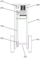
FIG. 1 is a front view of the present invention;
FIG. 2 is a front cross-sectional view of the present invention;
FIG. 3 is an enlarged schematic view of the present invention A;
fig. 4 is a partial structural view of the driving mechanism of the present invention.
In the figure: the device comprises a 1 moving plate, a 2 detection box, a 3 cavity, a 4 equipment cavity, a 5 hand push rod, a 6 driving mechanism, a 601 support, 602 rollers, 603 driving shafts, 604 stepping motors I, 605 pulleys, 606 belts, 607 blowers, 608 damping springs, 609 limiting rods, 610 lead screws, 611 stepping motors II, 612 bevel gears, 7 supporting mechanisms, 701 moving plates, 702 through holes, 703 connecting frames, 704 sliding rods, 705 racks, 706 spur gears, 707 bases, 708 worms and 709 cranks.
Detailed Description
The technical solutions in the embodiments of the present invention will be clearly and completely described below with reference to the drawings in the embodiments of the present invention, and it is obvious that the described embodiments are only a part of the embodiments of the present invention, and not all of the embodiments.
Examples of which are illustrated in the accompanying drawings, wherein like reference numerals refer to the same or similar elements or elements having the same or similar function throughout. The embodiments described below with reference to the drawings are illustrative and intended to be illustrative of the invention and are not to be construed as limiting the invention.
In the description of the present invention, it is to be understood that the terms "central," "longitudinal," "lateral," "length," "width," "thickness," "upper," "lower," "front," "rear," "left," "right," "vertical," "horizontal," "top," "bottom," "inner," "outer," "clockwise," "counterclockwise," "axial," "radial," "circumferential," and the like are used in the orientations and positional relationships indicated in the drawings for convenience in describing the invention and to simplify the description, and are not intended to indicate or imply that the referenced devices or elements must have a particular orientation, be constructed and operated in a particular orientation, and are therefore not to be considered limiting of the invention.
In the present invention, unless otherwise expressly stated or limited, the terms "mounted," "connected," "secured," and the like are to be construed broadly and can, for example, be fixedly connected, detachably connected, or integrally formed; can be mechanically or electrically connected; either directly or indirectly through intervening media, either internally or in any other relationship. The specific meanings of the above terms in the present invention can be understood by those skilled in the art according to specific situations.
As shown in fig. 1 to 4, the inspection equipment for electric power safe operation tour comprises a movable plate 1 and a detection box 2, wherein four universal wheels are fixedly connected to the bottom of the movable plate 1, the four universal wheels are respectively and fixedly connected to four corners of the bottom of the movable plate 1, a hand push rod 5 is arranged on the left side of the movable plate 1, the bottom of the hand push rod 5 is hinged to the left side of the movable plate 1, an equipment cavity 4 is formed inside the detection box 2, a cavity 3 is formed on the left side inside the detection box 2, a driving mechanism 6 is arranged inside the cavity 3, and supporting mechanisms 7 are arranged at four corners of the movable plate 1;
the driving mechanism 6 comprises a bracket 601 and two rollers 602, two sides of the two rollers 602 are rotatably connected with the bottom of the bracket 601, a driving shaft 603 is fixedly connected between the two rollers 602, a stepping motor I604 is arranged on the top of the inner wall of the bracket 601, a rubber seat is fixedly connected with the bottom of the stepping motor I604, one side of the rubber seat is fixedly connected with the inner wall of the bracket 601, the top of the stepping motor I604 is fixedly connected with a damping spring 608, the top of the damping spring 608 is fixedly connected with the top of the inner wall of the bracket 601, the top of the inner wall of the bracket 601 is fixedly connected with a blower 607, an air port of the blower 607 faces the stepping motor I604, one end of the stepping motor I604 and the middle part of the driving shaft 603 are fixedly connected with a belt pulley 605, the two belt pulleys 605 are in transmission connection, two limiting rods 609 and a lead screw 610 are arranged inside the cavity 3, the upper and lower ends of the two limiting rods, the middle parts of the two limiting rods 609 are slidably connected with the top of the bracket 601, the middle part of the lead screw 610 is in threaded connection with the top of the bracket 601, the top of the inner wall of the cavity 3 is fixedly connected with a stepping motor II611, one end of the stepping motor II611 and the top of the lead screw 610 are both fixedly connected with bevel gears 612, and the two bevel gears 612 are meshed;
the supporting mechanism 7 comprises a movable plate 701, a rubber seat is fixedly connected to the bottom of the movable plate 701, the rubber seat is in a horn shape, a connecting frame 703 is fixedly connected to the top of the movable plate 1, a sliding rod 704 is fixedly connected to the top of the inner wall of the connecting frame 703, the bottom of the sliding rod 704 is in sliding connection with the top of the movable plate 701, through holes 702 are formed in two sides of the movable plate 1, the movable plate 701 extends to the lower portion of the movable plate 1 through the through holes 702, a rack 705 is fixedly connected to one side of the movable plate 701, a spur gear 706 is arranged on one side of the rack 705, the spur gear 706 is meshed with the rack 705, a base 707 is arranged below the spur gear 706, the spur gear 706 is in rotating connection with the top of the base 707, a worm 708 is arranged on one side of the spur gear 706, the bottom of the worm 708.
When the device is used, the screw 610 is driven to rotate by the stepping motor II611, then the screw 610 drives the bracket 601 to move up and down, the roller 602 at the bottom of the bracket 601 is in contact with the ground, then the driving shaft 603 is driven to rotate by the stepping motor I604, then the driving shaft 603 drives the two rollers 602 to rotate, so that the device is convenient to move, the worm 708 is driven to rotate by rotating the crank 709, then the spur gear 706 rotates, the spur gear 706 drives the rack 705 to move up and down, so that the rack 705 drives the movable plate 701 to move up and down, and therefore the rubber seat at the bottom of the movable plate 701 is in contact.
In summary, the driving mechanism 6 is disposed inside the cavity 3, when the device needs to move, the screw 610 is driven to rotate by the stepping motor II611, then the screw 610 drives the bracket 601 to move up and down, the roller 602 at the bottom of the bracket 601 contacts with the ground, then the driving shaft 603 is driven to rotate by the stepping motor I604, then the driving shaft 603 drives the two rollers 602 to rotate, so that the device is convenient to move, the crank 709 is driven to rotate the worm 708, then the spur gear 706 rotates, the spur gear 706 drives the rack 705 to move up and down, so that the rack 705 drives the movable plate 701 to move up and down, so that the rubber seat at the bottom of the movable plate 701 contacts with the ground, and when the device does not need to move, the device can be kept still with the ground, and the detection work is convenient.
Although embodiments of the present invention have been shown and described above, it is understood that the above embodiments are exemplary and should not be construed as limiting the present invention, and that variations, modifications, substitutions and alterations can be made in the above embodiments by those of ordinary skill in the art without departing from the principle and spirit of the present invention. Any modification, equivalent replacement, or improvement made within the spirit and principle of the present invention should be included in the protection scope of the present invention.
Claims (8)
1. The utility model provides an electric power safe operation inspection tour check out test set, includes movable plate (1) and detection case (2), its characterized in that: a cavity (3) is formed in the left side of the interior of the detection box (2), a driving mechanism (6) is arranged in the cavity (3), and supporting mechanisms (7) are arranged at four corners of the movable plate (1);
the driving mechanism (6) comprises a support (601) and two rollers (602), two sides of the two rollers (602) are rotatably connected with the bottom of the support (601), a driving shaft (603) is fixedly connected between the two rollers (602), a stepping motor I (604) is arranged on the top of the inner wall of the support (601), one end of the stepping motor I (604) is fixedly connected with a belt pulley (605) in the middle of the driving shaft (603), the two belt pulleys (605) are in transmission connection through a belt (606), two limiting rods (609) and a lead screw (610) are arranged inside the cavity (3), the upper ends and the lower ends of the two limiting rods (609) and the lead screw (610) are fixedly connected with the top of the inner wall of the cavity (3) and the bottom of the inner wall of the cavity (3) respectively, and the middle parts of the two limiting rods (609) are in sliding connection with the top of the support (601), the middle part of lead screw (610) and the top threaded connection of support (601), the inner wall top fixedly connected with step motor II (611) of cavity (3), the equal fixedly connected with bevel gear (612) in one end of step motor II (611) and the top of lead screw (610), two bevel gear (612) meshing.
2. The electric power safe operation patrol detection device according to claim 1, characterized in that: the supporting mechanism (7) comprises a movable plate (701), through ports (702) are formed in two sides of the movable plate (1), the movable plate (701) extends to the lower portion of the movable plate (1) through the through ports (702), a rack (705) is fixedly connected to one side of the movable plate (701), a spur gear (706) is arranged on one side of the rack (705), the spur gear (706) is meshed with the rack (705), a base (707) is arranged below the spur gear (706), the spur gear (706) is rotatably connected with the top of the base (707), a worm (708) is arranged on one side of the spur gear (706), the bottom of the worm (708) is rotatably connected with the upper surface of the movable plate (1) through a rotating shaft, the worm (708) is meshed with the spur gear (706), and a crank (709) is fixedly connected to the top of the worm (708).
3. An electric power safe operation patrol detection device according to claim 1 or 2, characterized in that: the movable detection device is characterized in that a hand push rod (5) is arranged on the left side of the movable plate (1), the bottom of the hand push rod (5) is hinged to the left side of the movable plate (1), and an equipment cavity (4) is formed in the detection box (2).
4. The electric power safe operation patrol detection device according to claim 1, characterized in that: the bottom of the movable plate (1) is fixedly connected with four universal wheels, and the four universal wheels are respectively and fixedly connected with four corners of the bottom of the movable plate (1).
5. The electric power safe operation patrol detection device according to claim 1, characterized in that: the bottom fixedly connected with rubber seat of step motor I (604), one side of rubber seat and the inner wall fixed connection of support (601), the top fixed connection and damping spring (608) of step motor I (604), the top of damping spring (608) and the inner wall top fixed connection of support (601).
6. The electric power safe operation patrol detection device according to claim 1, characterized in that: the top of the inner wall of the support (601) is fixedly connected with a blower (607), and an air opening of the blower (607) faces to the stepping motor I (604).
7. The electric power safe operation patrol detection device according to claim 1, characterized in that: the bottom fixedly connected with rubber seat of fly leaf (701), the shape of rubber seat is tubaeform.
8. The electric power safe operation patrol detection device according to claim 1, characterized in that: the top of the movable plate (1) is fixedly connected with a connecting frame (703), the top of the inner wall of the connecting frame (703) is fixedly connected with a sliding rod (704), and the bottom of the sliding rod (704) is slidably connected with the top of the movable plate (701).
Priority Applications (1)
| Application Number | Priority Date | Filing Date | Title |
|---|---|---|---|
| CN202011486700.8A CN112769070A (en) | 2020-12-16 | 2020-12-16 | Power safety operation inspection tour check out test set |
Applications Claiming Priority (1)
| Application Number | Priority Date | Filing Date | Title |
|---|---|---|---|
| CN202011486700.8A CN112769070A (en) | 2020-12-16 | 2020-12-16 | Power safety operation inspection tour check out test set |
Publications (1)
| Publication Number | Publication Date |
|---|---|
| CN112769070A true CN112769070A (en) | 2021-05-07 |
Family
ID=75695410
Family Applications (1)
| Application Number | Title | Priority Date | Filing Date |
|---|---|---|---|
| CN202011486700.8A Pending CN112769070A (en) | 2020-12-16 | 2020-12-16 | Power safety operation inspection tour check out test set |
Country Status (1)
| Country | Link |
|---|---|
| CN (1) | CN112769070A (en) |
Cited By (1)
| Publication number | Priority date | Publication date | Assignee | Title |
|---|---|---|---|---|
| CN113790752A (en) * | 2021-08-12 | 2021-12-14 | 舒城县周瑜体育用品有限公司 | Badminton processing is with weaving check out test set |
Citations (4)
| Publication number | Priority date | Publication date | Assignee | Title |
|---|---|---|---|---|
| CN107757571A (en) * | 2017-11-30 | 2018-03-06 | 南京灿华光电设备有限公司 | A kind of solar telephone with lateral driving functions based on Internet of Things |
| CN208700523U (en) * | 2018-08-15 | 2019-04-05 | 中国南方电网有限责任公司超高压输电公司百色局 | A kind of portable power maintenance of equipment aerial device |
| CN209010102U (en) * | 2018-08-20 | 2019-06-21 | 江苏博创升降机械有限公司 | A kind of trackless elevator being movably walking |
| CN210193328U (en) * | 2019-06-25 | 2020-03-27 | 国网河南省电力公司确山县供电公司 | Tool vehicle for maintaining power equipment |
-
2020
- 2020-12-16 CN CN202011486700.8A patent/CN112769070A/en active Pending
Patent Citations (4)
| Publication number | Priority date | Publication date | Assignee | Title |
|---|---|---|---|---|
| CN107757571A (en) * | 2017-11-30 | 2018-03-06 | 南京灿华光电设备有限公司 | A kind of solar telephone with lateral driving functions based on Internet of Things |
| CN208700523U (en) * | 2018-08-15 | 2019-04-05 | 中国南方电网有限责任公司超高压输电公司百色局 | A kind of portable power maintenance of equipment aerial device |
| CN209010102U (en) * | 2018-08-20 | 2019-06-21 | 江苏博创升降机械有限公司 | A kind of trackless elevator being movably walking |
| CN210193328U (en) * | 2019-06-25 | 2020-03-27 | 国网河南省电力公司确山县供电公司 | Tool vehicle for maintaining power equipment |
Cited By (1)
| Publication number | Priority date | Publication date | Assignee | Title |
|---|---|---|---|---|
| CN113790752A (en) * | 2021-08-12 | 2021-12-14 | 舒城县周瑜体育用品有限公司 | Badminton processing is with weaving check out test set |
Similar Documents
| Publication | Publication Date | Title |
|---|---|---|
| CN209375814U (en) | An intelligent security monitoring camera with an alarm device | |
| CN207879142U (en) | A kind of automobile glass lifting device | |
| CN219905388U (en) | Glass rack | |
| CN112326989A (en) | Laser speed measuring device of extra-high voltage circuit breaker | |
| CN216424596U (en) | Carriage cabin body extension transmission system | |
| CN214119429U (en) | Be used for environment monitoring device for building safety | |
| CN219057105U (en) | Water pollution sample storage device | |
| CN213271675U (en) | Industry display device based on internet | |
| CN116665556A (en) | Liquid crystal display with plug-in card type main board assembly structure | |
| CN210376720U (en) | Self-powered detection door | |
| CN118688536B (en) | A convenient and mobile device and method for diagnosing power plant equipment operation faults | |
| CN209940374U (en) | Lifting platform for assembling and welding vehicle frame | |
| CN223976970U (en) | Automobile lampshade checking fixture | |
| CN111622661A (en) | An electric climbing ladder | |
| CN217097654U (en) | Adjustable optical fiber moving platform | |
| CN219914853U (en) | Performance test bench for driving speed reducing mechanism | |
| CN224043356U (en) | Chamfering and edging device for screen glass processing | |
| CN222534978U (en) | Combined high-low temperature test box | |
| CN220437461U (en) | Embedded vision detection equipment | |
| CN221004679U (en) | Protective equipment for motor processing | |
| CN114890027B (en) | A management device for electric power material storage | |
| CN215573779U (en) | Tricycle production is with self-control utensil of examining | |
| CN220810379U (en) | Portable dust particle counter | |
| CN211859320U (en) | Light energy storage device with bidirectional converter | |
| CN223884844U (en) | A low-voltage distribution box that is easy to maintain |
Legal Events
| Date | Code | Title | Description |
|---|---|---|---|
| PB01 | Publication | ||
| PB01 | Publication | ||
| SE01 | Entry into force of request for substantive examination | ||
| SE01 | Entry into force of request for substantive examination | ||
| RJ01 | Rejection of invention patent application after publication | ||
| RJ01 | Rejection of invention patent application after publication |
Application publication date: 20210507 |