Pneumatic conveying system for dry dedusting fine ash of converter gas
Technical Field
The invention relates to the technical field of fine ash pneumatic conveying equipment, in particular to a converter gas dry dedusting fine ash pneumatic conveying system.
Background
With the continuous enhancement of environmental awareness, most of newly-built converters adopt dry dedusting, and the conveying technology of the dry dedusting mainly adopts pneumatic conveying.
The prior patent (application number is CN201820146230.2) discloses a light medium co-flow pneumatic conveying system, which comprises a positive pressure dense phase pneumatic conveying system and a light medium material negative pressure suction pneumatic conveying system, wherein the light medium material and the conveying material are jointly mixed and conveyed. The positive pressure dense-phase pneumatic conveying system comprises a high-pressure air source, a co-flow conveying pipeline, a light medium feeding device and a coarse and heavy conveying material feeding device. The outlet of the co-current conveying pipeline is connected with a co-current material collector, the discharge port of the co-current material collector is connected with a light and heavy material separator, and the discharge port of the light and heavy material separator is connected with a light medium material box and a heavy and heavy conveying material box. The product has the advantages of low dense-phase pneumatic conveying energy consumption, no material breakage, less pipe wall abrasion and wide application range of dilute-phase pneumatic conveying, can be used for low-speed dense-phase conveying of materials which are difficult to convey, such as large granularity, heavy weight, frangibility and the like, can effectively expand the application range of dense-phase pneumatic conveying, and can be widely applied to the industrial field. The pneumatic conveying system has the advantages of low dense-phase pneumatic conveying energy consumption and no material breakage.
The traditional pneumatic conveying system usually utilizes an air compressor to provide air, and moisture in the air easily causes deliquescence of fine ash and wall adhesion. In addition, when discharging, the problem of fine ash flying is easily caused because of too little water.
Disclosure of Invention
The invention mainly aims to solve the problems that in the prior art, the air compressor is often used for providing air for the traditional pneumatic conveying system, and fine ash is easy to deliquesce and cause wall adhesion due to moisture existing in the air. And when the material is discharged, the problem of fine ash flying is easily caused because the water content is too little.
In order to achieve the purpose, the invention adopts the following technical scheme:
a pneumatic conveying system for fine ash generated in dry dedusting of converter gas comprises a bin type pump, a fine ash warehouse, a gas storage tank, an ash collecting hopper and a humidifying component, wherein the bin type pump, the fine ash warehouse, the gas storage tank, the ash collecting hopper and the humidifying component are fixed on the ground;
the humidifying component comprises a humidifying barrel, the bottom end of the humidifying barrel is fixed on the ground, a plurality of first spray heads are fixed on the surface of the inner wall of the humidifying barrel, a rotary joint is fixed on the central axis of a radial plane at the top end of the humidifying barrel, the bottom end of the rotary joint penetrates through a shell at the top end of the humidifying barrel and extends into the humidifying barrel, and is connected with a rotary water pipe, one end of the rotary water pipe, far away from the rotary joint, is rotatably connected with the inner wall at the bottom end of the humidifying barrel through a bearing, a second spray head is fixed at the top end of the rotary water pipe, and a plurality of stirring blades which are symmetrically arranged in pairs are sequentially fixed on the outer peripheral surface of the rotary water pipe from top to bottom;
the air storage tank is connected with the bin pump and the humidifying assembly through the drying assembly, the drying assembly comprises a drying tower fixed on the ground, the drying tower is connected with the bin pump and the air storage tank through air conveying pipes, and the drying tower is connected with the humidifying barrel through a fan.
Furthermore, the humidifying component is connected with the push plate component, the push plate component comprises two cylinders, the bottom end of each cylinder is fixed on the top surface of the humidifying barrel, the two cylinders are symmetrically arranged by taking a rotary joint as a central shaft, a piston rod of each cylinder penetrates through the shell of the gas storage tank and extends into the gas storage tank to be connected with the annular lifting plate, and a plurality of T-shaped plugs which correspond to the first spray heads one by one are fixed on the bottom surface of the annular lifting plate.
Furthermore, the longitudinal section of the annular lifting plate is disc-shaped, a through hole for the insertion of the rotary water pipe is formed in the shell of the annular lifting plate, and the cross section of the inner cavity of the through hole is isosceles trapezoid.
Further, the inner wall embedding of through-hole has a plurality of balls, and is a plurality of the ball encircles the radial planar axis of through-hole sets up equidistance one by one.
Furthermore, an inclined packing auger is fixed on the surface of the bottom end of the humidifying barrel.
Furthermore, two ash guide blades are fixed at the top end of the rotating water pipe, the two ash guide blades are symmetrically arranged by taking the rotating water pipe as a central shaft, and the relative height of the two ash guide blades is greater than that of the first spray head.
Furthermore, the longitudinal section of each ash guiding blade is triangular.
Further, the fan is fixed in subaerial, the fan is connected with the filter screen through the gas-supply pipe, the filter screen is fixed in on the humidification bucket top inner wall.
Further, the bottom of ash collecting bucket is connected with humidification bucket top through transporting grey pipe, it keeps away from to transport grey pipe the one end of ash collecting bucket runs through the humidification bucket and extends to the inside top of humidification bucket.
Further, the humidification subassembly is connected with the power subassembly, the power subassembly includes first sprocket, first sprocket is fixed in rotary joint's rotor outer peripheral face, one side of first sprocket is connected with the second sprocket through the chain, the second sprocket is fixed in the outer peripheral face of motor output shaft, the motor is fixed in humidification bucket outer peripheral face.
Compared with the prior art, the invention has the beneficial effects that:
(1) the invention can control the dryness and humidity in the pneumatic conveying system, thereby preventing fine ash from being bonded in the bin pump due to excessive moisture and from flying due to insufficient moisture during discharging.
The method specifically comprises the following steps: through the cooperation of drying assembly and humidification subassembly to utilize the drying tower among the drying assembly to absorb the inside moisture of carrying to the storehouse formula pump gas of gas holder, prevent that this moisture and fine ash from combining together, lead to the fine ash to produce the damp knot phenomenon in storehouse formula pump. In the transportation process, the inside fine ash of collection ash bucket can enter into to the humidification bucket through fortune ash pipe to utilize the first shower nozzle on the humidification bucket inner wall and the second shower nozzle jet stream on the rotatory water pipe, make the fine ash that enters into to the humidification bucket condense, and by the stirring vane stirring on the rotatory water pipe, finally carry through oblique auger.
(2) The invention can change the adsorption effect of the humidifying component on the fine ash.
The method specifically comprises the following steps: gather when cylinder piston rod promotes the annular lifter plate in the humidification bucket through the push pedal subassembly and go up and down to through the distance between change T font end cap and the first shower nozzle, adjust the spray effect of first shower nozzle rivers, thereby when thin ash enters the humidification bucket for the beginning, increase the distance between annular lifter plate and the first shower nozzle, make atomized water fully contact with the thin ash in top. Otherwise, the distance between the annular lifting plate and the first spray head is reduced, so that the water flow of the first spray head directly falls into the bottom end of the humidifying barrel after being reflected by the T-shaped plug to increase the viscosity of fine ash.
Additional features and advantages of the disclosure will be set forth in the description which follows, or in part may be learned by the practice of the above-described techniques of the disclosure, or may be learned by practice of the disclosure.
In order to make the aforementioned and other objects, features and advantages of the present invention comprehensible, preferred embodiments accompanied with figures are described in detail below.
Drawings
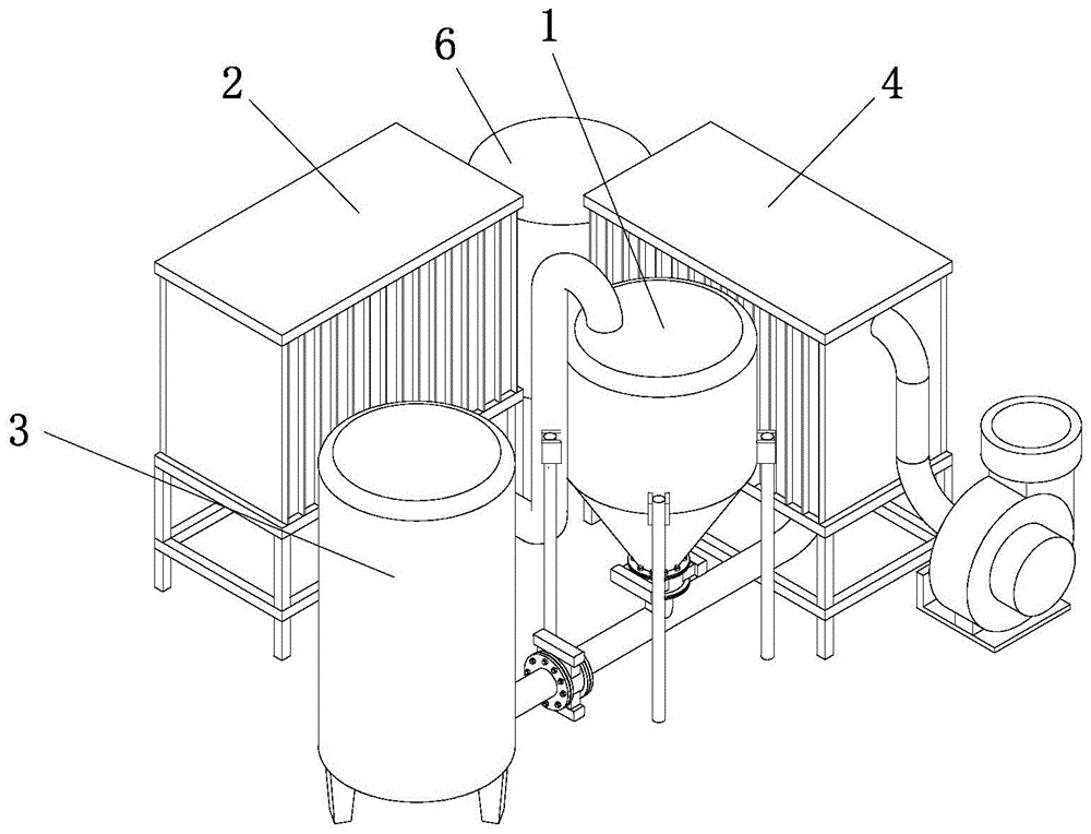
FIG. 1 is a schematic view of the overall structure of a pneumatic conveying system for dry dedusting fine ash of converter gas according to the present invention;
FIG. 2 is a flow chart of the operation of the pneumatic conveying system for dry dedusting and fine ash of converter gas provided by the invention;
FIG. 3 is a schematic structural diagram of a humidifying component in the converter gas dry dedusting fine ash pneumatic conveying system provided by the invention;
FIG. 4 is a schematic structural diagram of a push plate assembly in the converter gas dry dedusting fine ash pneumatic conveying system provided by the invention;
FIG. 5 is an enlarged view of the structure of the portion "A" in FIG. 4;
FIG. 6 is a schematic structural diagram of a power assembly in the converter gas dry dedusting fine ash pneumatic conveying system provided by the invention.
Description of the main symbols:
| bin type pump
|
1
|
Second nozzle
|
64
|
| Fine ash storehouse
|
2
|
First nozzle
|
65
|
| Gas storage tank
|
3
|
Rotary joint
|
66
|
| Dust collecting bucket
|
4
|
Ash guiding blade
|
67
|
| Ash conveying pipe
|
41
|
Inclined auger
|
68
|
| Drying assembly
|
5
|
Push plate assembly
|
7
|
| Drying tower
|
51
|
Annular lifting plate
|
71
|
| Fan blower
|
52
|
Through hole
|
72
|
| Filter screen
|
53
|
T-shaped plug
|
73
|
| Humidifying assembly
|
6
|
Power assembly
|
8
|
| Humidifying barrel
|
61
|
First chain wheel
|
81
|
| Rotary water pipe
|
62
|
Second chain wheel
|
82
|
| Stirring blade
|
63
|
Electric machine
|
83 |
Detailed Description
The technical solutions in the embodiments of the present invention will be clearly and completely described below with reference to the drawings in the embodiments of the present invention, and it is obvious that the described embodiments are only a part of the embodiments of the present invention, and not all of the embodiments. All other embodiments, which can be derived by a person skilled in the art from the embodiments given herein without making any creative effort, shall fall within the protection scope of the present invention.
Referring to fig. 1 to 4, a pneumatic conveying system for dry dedusting fine ash of converter gas comprises a bin pump 1 fixed on the ground, a fine ash storage 2, a gas storage tank 3, an ash collecting hopper 4 and a humidifying assembly 6.
Wherein, the top of storehouse formula pump 1 is connected with fine ash storehouse 2 through defeated ash pipe, and 1 bottoms of storehouse formula pump are connected with gas holder 3 and dust collection bucket 4 through pneumatic double gate valve. Wherein the dust collecting hopper 4 is connected with the humidifying component 6.
Specifically, the humidifying assembly 6 includes a humidifying cylinder 61, and the bottom end of the humidifying cylinder 61 is fixed on the ground. A plurality of first nozzles 65 are fixed to the inner wall surface of the humidification barrel 61, and a rotary joint 66 is fixed to the central axis of the top end radial plane of the humidification barrel 61. Wherein, the bottom end of the rotary joint 66 penetrates through the top shell of the humidifying barrel 61 and extends to the interior of the humidifying barrel 61 to be connected with the rotary water pipe 62. One end of the rotating water pipe 62 far away from the rotating joint 66 is rotatably connected with the inner wall of the bottom end of the humidifying barrel 61 through a bearing.
The top end of the rotating water pipe 62 is fixed with a second nozzle 64, and the peripheral surface of the rotating water pipe 62 is sequentially fixed with a plurality of stirring blades 63 which are arranged symmetrically in pairs from top to bottom. In the embodiment, the air storage tank 3 is connected with the bin pump 1 and the humidifying component 6 through the drying component 5. The drying assembly 5 includes a drying tower 51 fixed on the ground, the drying tower 51 is connected with the bin pump 1 and the air storage tank 3 through air pipes, and the drying tower 51 is connected with the humidifying barrel 61 through a fan 52.
Referring to fig. 3, the humidifying assembly 6 is connected to the push plate assembly 7. The push plate assembly 7 includes two air cylinders 75, and the bottom end of each air cylinder 75 is fixed on the top surface of the humidifying cylinder 61. Two the cylinder 75 uses rotary joint 66 to set up as the central axis symmetry, every the cylinder 75 piston rod all runs through 3 shells of gas holder and extends to inside being connected with annular lifter plate 71 of gas holder 3.
In this embodiment, a plurality of T-shaped plugs 73 are fixed to the bottom end surface of the annular elevating plate 71 so as to correspond one by one to the first showerhead 65. This arrangement enables the piston rod of the cylinder 75 to push the annular lifting plate 71 in the humidification barrel 61 to lift, and the bottom end of the annular lifting plate 71 is fixed with a plurality of T-shaped plugs 73 corresponding to the first nozzles 65 in the humidification barrel 61 one by one, so as to adjust the water flow spraying effect of the first nozzles 65 by changing the distance between the T-shaped plugs 73 and the first nozzles 65. Further, when the fine ash is initially introduced into the humidifying cylinder 61, the distance between the annular elevating plate 71 and the first spray nozzle 65 is increased, so that the atomized water flow is sufficiently contacted with the fine ash at the top end. Conversely, the distance between the annular lifting plate 71 and the first nozzle 65 is reduced, so that the water flow of the first nozzle 65 directly falls into the bottom end of the humidifying barrel 61 after being reflected by the T-shaped plug 73 to increase the viscosity of the fine ash.
Specifically, please refer to fig. 3, wherein an inclined packing auger 68 is fixed on the bottom end surface of the humidifying barrel 61. This setting can make humidification bucket 61 can pass through the oblique auger 68 that the bottom was fixed, transports the fine ash that bonds inside to the eminence again to the transport of transport vechicle provides convenience.
Specifically, referring to fig. 3 again, two dust guide vanes 67 are fixed to the top end of the rotating water pipe 62, and the two dust guide vanes 67 are symmetrically arranged with the rotating water pipe 62 as a central axis. Wherein the relative height of the two ash guide vanes 67 is greater than the relative height of the first spray head 65. This setting can make the ash guide blade 67 on the rotatory water pipe 62 follow rotatory water pipe 62 when rotatory, because ash guide blade 67 and first shower nozzle 65 are in same horizontal plane together to the angle displacement that utilizes ash guide blade 67 drives the fine ash of just going into the humidification bucket 61 inner chamber and breaks up along with the guiding of pivoted ash guide blade 67, and then improves the atomization effect of first shower nozzle 65. In the present embodiment, each of the dust guide blades 67 has a triangular longitudinal section, so that the water flow jetted to the dust guide blades 67 can slide off rapidly by means of the inclined surface thereof.
Specifically, please refer to fig. 3 again, the fan 52 is fixed on the ground, and the fan 52 is connected to the filter screen 53 through the air pipe. Wherein, the filter screen 53 is fixed on the inner wall of the top end of the humidifying barrel 61. Because the fan 52 is connected with the filter screen 53 on the inner wall of the top end of the humidifying barrel 61 through the air conveying pipe, the filter screen 53 is utilized to reduce fine ash entering the fan 52, and then entering the drying tower 51 through the fan 52 to pollute the drying tower 51.
In this embodiment, the bottom end of the dust hopper 4 is connected to the top end of the humidifying cylinder 61 through the dust conveying pipe 41. One end of the ash conveying pipe 41, which is far away from the ash collecting hopper 4, penetrates through the humidifying barrel 61 and extends to the top end of the interior of the humidifying barrel 61. It can be understood that this arrangement allows the dust hopper 4 to convey the fine dust inside thereof to the inside of the humidifying cylinder 61 through the dust conveying pipe 41, and facilitates the absorption thereof by the first and second spraying heads 65 and 64 since the dust conveying pipe 41 extends only to the top end of the inside of the humidifying cylinder 61.
Specifically, referring again to fig. 3 and 4, the longitudinal section of the annular elevating plate 71 is dish-shaped. It will be appreciated that this arrangement allows the water stream directed towards the annular lifter plate 71 to slide off rapidly through its inclined surface. Meanwhile, a through hole 72 through which the rotary water pipe 62 is inserted is formed in the casing of the annular elevating plate 71. The cross section of the inner cavity of the through hole 72 is isosceles trapezoid, so that the water flow of the second nozzle 64 can rapidly slide off the inclined plane formed by the inner wall of the through hole 72 of the annular lifting plate 71, and the inclined plane changes the distance between the inclined plane and the second nozzle 64 by lifting along with the annular lifting plate 71, thereby changing the atomization effect of the second nozzle 64.
Specifically, referring to fig. 4 and 5, a plurality of balls 721 are embedded in the inner wall of the through hole 72, and the balls 721 are disposed at equal intervals around the central axis of the radial plane of the through hole 72. This arrangement allows the inner wall of the through-hole 72 to roll on the outer surface of the second head 64 by the balls 721, to prevent dry friction between the inner wall of the through-hole 72 and the second head 64.
Referring to fig. 6, the humidifying assembly 6 is connected with a power assembly 8. Specifically, the power assembly 8 includes a first sprocket 81, and the first sprocket 81 is fixed to the outer peripheral surface of the rotor of the rotary joint 66. In this embodiment, one side of the first chain wheel 81 is connected to a second chain wheel 82 via a chain, and the second chain wheel 82 is fixed to the outer peripheral surface of the output shaft of the motor 83. Wherein the motor 83 is fixed to an outer circumferential surface of the humidification tub 61. This arrangement allows the output shaft of the motor 83 to rotate the second sprocket 82 thereon, and the second sprocket 82 is connected to the first sprocket 81 on the rotor of the rotary joint 66 via a chain, so as to transmit the torque to the first sprocket 81 on the rotor of the rotary joint 66 and drive the rotary joint 66 to rotate.
The specific operation mode of the invention is as follows:
when the pneumatic conveying system is used for conveying the fine ash, the following steps are required:
1. feeding: firstly, opening a valve at the bottom end of the fine ash storehouse 2 to enable the fine ash collected in the fine ash storehouse 2 to flow into the bin pump 1 by virtue of gravity or a fan, then closing the valve at the bottom end of the fine ash storehouse 2, and ending the feeding program.
2. Fluidization: the pneumatic double-gate board in the bottom end of the bin type pump 1 is opened, the introduced gas comes from the gas in the gas storage tank 3 connected with the bin type pump 1 through the gas transmission pipe, the fine ash in the bin type pump 1 is fully fluidized, the pressure is continuously increased, when the pressure reaches the working pressure, the pneumatic double-gate board in the bottom end of the bin type pump 1 is opened again, and the fluidization program is ended.
3. Conveying: the fine ash fluidized in the bin pump 1 enters an ash conveying pipe between the bin pump and the ash collecting hopper 4 through the pneumatic double gate plate, and then is conveyed into the ash collecting hopper 4 through the ash conveying pipe until the pressure in the ash collecting hopper 4 begins to reduce, and a conveying cycle is ended and the next cycle is restarted.
4. In the above steps, there is a humidity control process: because be equipped with drying assembly 5 between bin pump 1 and the gas holder 3 to utilize the drying tower 51 among the drying assembly 5 to absorb the moisture of the gas of conveying to bin pump 1 in the gas holder 3 inside, prevent that this moisture combines together with the fine ash, lead to the fine ash to produce the damp knot phenomenon in bin pump 1.
In addition, during the conveying process, the fine ash in the ash collecting hopper 4 enters the humidifying cylinder 61 through the ash conveying pipe 41, so that the first spray head 65 on the inner wall of the humidifying cylinder 61 and the second spray head 64 on the rotating water pipe 62 are utilized to spray water flow, so that the fine ash entering the humidifying cylinder 61 is condensed, is uniformly stirred by the stirring blade 63 on the rotating water pipe 62, and is finally conveyed through the inclined auger 68. In this process, the humid air in the humidification bucket 61 is recovered by the fan 52 to be dehumidified in the drying tower 51 to wait for the next dehumidification cycle.
The above description is only for the preferred embodiment of the present invention, but the scope of the present invention is not limited thereto, and any person skilled in the art should be considered to be within the technical scope of the present invention, and the technical solutions and the inventive concepts thereof according to the present invention should be equivalent or changed within the scope of the present invention.