Inner container structure for double-fan oven and oven with inner container structure
Technical Field
The invention relates to the field of double-fan ovens, in particular to a liner structure for a double-fan oven and an oven with the liner structure.
Background
In an air heater system of the oven, the air heater mainly blows out air heated by the heating pipe from an air outlet of the hot air baffle, and the hot air returns to the back of the oven from an air inlet of the hot air baffle after forming internal circulation in the inner container of the oven. At present, the oven in the market is mainly single fan, and the air heater is installed on the backplate of inner bag, and annular back heating pipe uses the motor shaft of air heater as the centre of a circle to install in the periphery of air heater, and hot-blast baffle is fixed in the inboard of inner bag backplate, covers circulating fan and back heating pipe, forms hot-blast room in hot-blast baffle. When the air heater and the back heating pipe work, the pressure at the center of the circulating fan is low, the pressure at the periphery of the circulating fan is high, the circulating fan sucks cold air from the air inlet of the center area, and the cold air is heated by the back heating pipe to become hot air which flows to the inner container from the air outlet. The hot air chamber sucks cold air from the center and blows hot air to the periphery, circulating hot air is formed in the inner container of the oven, and forced convection heat exchange is carried out on food on the baking tray in the inner container.
The single-fan oven has the defects that the air quantity of an air outlet is insufficient, hot air cannot reach a door body, and the problem of uneven coloring of baked food is solved. For solving this problem, the oven that adopts double fan has appeared on the market at present, and two air heaters set up from top to bottom in this kind of oven, and the back of hot-blast baffle sets up the baffle for each air heater is in independent hot-blast room respectively, compares with single fan oven, and the circulating air volume of double fan oven air outlet is enough big, and hot-blast can reach the door body and return air from the center again, covers all food surfaces. For example, the oven double-fan system disclosed in the chinese utility model patent No. ZL201721918690.4 (No. CN 207662174U).
However, the air outlets of the existing oven fan systems are symmetrically opened, but the air volume on one side is larger than that on the other side after the air heater rotates, so that the hot air flow cannot be uniformly distributed in the liner, the color on one side of the baked food is deeper than that on the other side, and the baking effect of the oven is affected.
Disclosure of Invention
The first technical problem to be solved by the invention is to provide an inner container structure for a double-fan oven, which has good temperature field uniformity, aiming at the prior art.
The second technical problem to be solved by the invention is to provide an inner container structure for a double-fan oven with good baking effect aiming at the prior art.
The third technical problem to be solved by the present invention is to provide an inner container structure for a dual-fan oven, which is suitable for both single-layer baking and dual-layer baking.
The fourth technical problem to be solved by the invention is to provide a double-fan oven with good baking effect aiming at the prior art.
The technical scheme adopted by the invention for solving at least one technical problem is as follows: the utility model provides an inner bag structure of double fan oven, includes the inner bag, be provided with the hot-blast baffle of utensil air intake in this inner bag, form hot-blast room between the backplate of this hot-blast baffle and inner bag, above-mentioned air intake includes last air intake and lower air intake, should go up, lower air intake sets up along the interval from top to bottom in the middle part of this hot-blast baffle, install last air heater and lower air heater that correspond respectively with above-mentioned upper and lower air intake in the above-mentioned hot-blast room, the baffle is transversely installed in the middle part level of upper and lower air intake on the back of above-mentioned hot-blast baffle, a serial communication port, the top exhaust vent has been seted up to one side of the roof of hot-blast baffle, and simultaneously, the bottom exhaust vent has been seted up to one side of the diapire of this hot-.
Further, the hole area of the top air outlet hole is larger than that of the bottom air outlet hole.
Furthermore, the two sides of the upper end of the hot air baffle are respectively provided with a first upper air outlet and a second upper air outlet, wherein the first upper air outlet and the top air outlet are arranged at the same side, the first upper air outlet and the second upper air outlet are basically at the same height, the movement track of the outer end of the fan blade of the upper hot air blower at the position adjacent to the height is from the first upper air outlet to the second upper air outlet, the first upper air outlet and the second upper air outlet are respectively formed by the upper air outlet, in addition, the number of the upper air outlet of the first upper air outlet is more than that of the second upper air outlet, meanwhile, the first upper air outlet can obliquely upwards exhaust air towards the corresponding liner side wall, and the second upper air outlet can horizontally exhaust air towards the corresponding liner side wall. The upper air outlet of the hot air baffle can be ensured by arranging the first upper air outlet and the second upper air outlet, when the upper air heater rotates, the hot air outlet direction of the upper air heater is along the tangential direction of the rotation of the fan blades, and the upper end of the hot air baffle can guide the air outlet of the upper air heater, so that the number of the upper air outlet holes of the first upper air outlet is more than that of the second upper air outlet, the left and right air outlet at the upper end of the hot air baffle is further uniform, and meanwhile, the first upper air outlet can obliquely upwards output air to the corresponding liner side wall, so that the hot air blown out from the first upper air outlet is firstly blown to the corresponding liner side wall and then rebounds to the baking tray, and the second upper air outlet can horizontally output air towards the corresponding liner side wall, thereby ensuring the hot air quantity of the upper portion of the liner on the.
Furthermore, a first middle air outlet and a second middle air outlet are respectively arranged at two ends of the middle part of the hot air baffle along the height direction, the second middle air outlet is arranged at the same side with the bottom air outlet, the first middle air outlet and the second middle air outlet are basically at the same height, and the movement track of the outer end of the fan blade of the lower hot air blower at the position adjacent to the height is from the first middle air outlet to the second middle air outlet. Through setting up air outlet in first air outlet and the second to guarantee the middle part air-out of hot-blast baffle.
In order to make the air outlet of the hot air baffle more uniform, the left lower end and the right lower end of the hot air baffle are respectively provided with a first lower air outlet and a second lower air outlet. The air outlet of the first upper air outlet, the air outlet of the second upper air outlet, the air outlet of the first middle air outlet and the air outlet of the second middle air outlet can be balanced by arranging the first lower air outlet and the second lower air outlet, so that hot air blown out from the hot air chamber is more uniform.
In order to enable air outlet on the left side and the right side of the lower end of the hot air baffle plate to be more uniform, the first lower air outlet and the second lower air outlet are arranged in bilateral symmetry along the vertical center line of the hot air baffle plate.
Further, the first lower air outlet and the second lower air outlet are respectively formed by lower air outlet holes, each lower air outlet hole is a vertically extending strip-shaped hole, and in each lower air outlet, the area of the lower air outlet hole positioned on the outer side is smaller than that of the lower air outlet hole positioned on the inner side. Because the air outlet direction of the lower air heater is along the tangential direction of the fan blades, the air outlet of each lower air outlet along the left-right direction can be uniform through the design.
Furthermore, the upper end of the hot air baffle is respectively provided with a first upper auxiliary air outlet and a second upper auxiliary air outlet, the first upper auxiliary air outlet and the second upper auxiliary air outlet are basically at the same height, the movement track of the outer end of the fan blade of the upper air heater at the position adjacent to the height is the first upper auxiliary air outlet to the second upper auxiliary air outlet, the hole area of the first upper auxiliary air outlet is smaller than that of the second upper auxiliary air outlet, the first upper auxiliary air outlet is positioned at one side of the upper air inlet, and the second upper auxiliary air outlet is positioned at the other side of the upper air inlet and above the upper air inlet. The horizontal air-out of following the air-out direction of last air heater can be realized to supplementary exhaust vent on the first, compromise the horizontal air-out of its place side simultaneously, and the horizontal air-out of giving consideration to in the place side simultaneously can be realized to supplementary exhaust vent on the second along the horizontal air-out of last air heater air-out direction, and through the setting of supplementary exhaust vent on first supplementary exhaust vent on and the second, it is more even to cooperate with air outlet on first upper air outlet and the second and enables the air-out of hot-blast baffle upper end.
In order to enable the first upper auxiliary air outlet and the second upper auxiliary air outlet to better meet the air outlet in the area between the first upper air outlet and the second upper air outlet, the first upper auxiliary air outlet and the second upper auxiliary air outlet are both transversely extending strip-shaped holes, and the width of the holes of the first upper auxiliary air outlet and the width of the second upper auxiliary air outlet are close to that of the strip-shaped holes.
In order to supplement the air outlet in the area between the first middle air outlet and the second middle air outlet, the middle part of the hot air baffle is respectively provided with a first middle auxiliary air outlet and a second middle auxiliary air outlet, the first middle auxiliary air outlet and the second middle auxiliary air outlet are basically at the same height, the movement track of the outer end of the fan blade of the lower air heater adjacent to the height is from the first middle auxiliary air outlet to the second middle auxiliary air outlet, the first middle auxiliary air outlet and the second middle auxiliary air outlet are positioned between the first middle air outlet and the second middle air outlet, and the hole area of the first middle auxiliary air outlet is larger than that of the second middle auxiliary air outlet. When the lower air heater rotates, the hot air outlet direction of the lower air heater is along the tangential direction of the rotation of the fan blades, and the partition plate can conduct flow guiding action on the outlet air of the lower air heater, so that the outlet air of the first middle auxiliary outlet hole and the outlet air of the second middle auxiliary outlet hole can be uniform, and the hole area of the first middle auxiliary outlet hole is larger than that of the second middle auxiliary outlet hole. Supplementary exhaust vent in being favorable to the upper strata of the food that lies in side support second floor in the double-deck is baked through supplementary exhaust vent in first and the second, can promote simultaneously toasting the food that lies in side support third floor in the single-deck is baked, and the bottom to food influences lessly simultaneously.
Furthermore, supplementary exhaust vent in first and the second is the rectangular hole of horizontal extension, and both widths are close, and the last hole of supplementary exhaust vent in each along its length direction respectively the level towards the formation hot-blast blend stop backward extension. The hot air blocking strips can prevent the air outlet of the auxiliary air outlet holes in each baking tray from being directly blown upwards and cannot be blown to the upper layer of the food corresponding to the baking tray in a large amount, and the hot air blocking strips can guide the air outlet of the auxiliary air outlet holes in each baking tray correspondingly, so that the hot air blocking strips can blow the food in the corresponding baking tray forwards and straightly.
For making first air outlet can be better to the air-out of its inner bag lateral wall slant that corresponds, and the air outlet can be better towards the horizontal air-out of its inner bag lateral wall direction that corresponds on the second, it is rectangular hole to go up the exhaust vent, and wherein, the last exhaust vent of above-mentioned first air outlet sets up along the extending direction of the hot-blast baffle's of its place lateral margin, and the last exhaust vent that lies in upper portion in the air outlet transversely sets up along the top edge of hot-blast baffle in the second, lies in the vertical setting of the last exhaust vent of lower part and leaves certain clearance with the lateral margin of hot-blast baffle.
Furthermore, the lower side of the first upper air outlet is provided with a middle upper air outlet, the middle upper air outlet is positioned above the partition plate, the first middle air outlet and the second middle air outlet are respectively formed by middle air outlet holes, the number of the middle air outlet holes of the first middle air outlet is less than that of the second middle air outlet, and the first middle air outlet and the second middle air outlet can respectively exhaust air to the front of the side where the middle air outlet holes are positioned. The air outlet of the upper air heater can be fully utilized by arranging the middle and upper air outlet, and the middle and upper air outlet can supplement the air outlet in the middle of the hot air baffle.
In order to guide the heat at the upper heating pipe to food more fully, the top air outlet is a long hole extending along the length direction of the top wall of the hot air baffle, and the length of the top air outlet is 40% -60% of the length of the top wall of the hot air baffle.
For avoiding the bottom to color deeply, the hole area of bottom exhaust vent is less than the top exhaust vent, the bottom air outlet is the rectangular hole that extends along the length direction of hot-blast baffle diapire, and the length of this bottom exhaust vent is 20% ~ 40% of hot-blast baffle bottom length.
In order to stably realize the installation of the side bracket, the hot air baffle is provided with an installation hole for installing the side bracket.
The technical scheme adopted for solving the fourth technical problem is as follows: a double-fan oven with the inner container structure is provided.
Compared with the prior art, the invention has the advantages that: the partition plate is arranged between the upper air heater and the lower air heater, so that mutual interference of air outlets of the upper air heater and the lower air heater can be avoided, in addition, the heat at the upper heating pipe in the inner container can be guided to food through the air outlet of the air outlet hole at the top, the food coloring effect of the heat at the upper end of the baking tray is more obvious, the cooking effect is improved, and particularly, the baking tray placed on the third layer of the side support in single-layer baking and the baking tray placed on the fourth layer of the side support in double-layer baking are improved. The bottom air outlet can balance the air outlet of the top air outlet, and can color the bottom of food, especially a baking tray placed on the third layer of the side bracket in single-layer baking and a baking tray placed on the second layer of the side bracket in double-layer baking.
Drawings
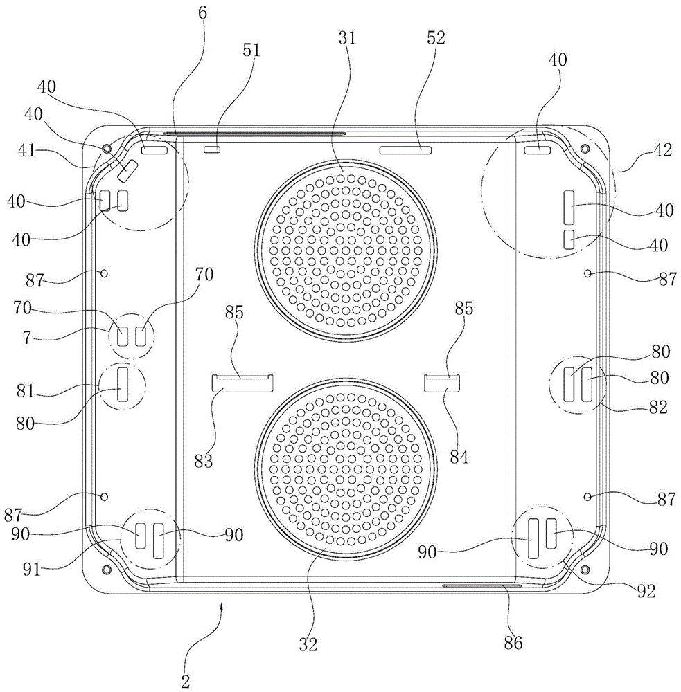
Fig. 1 is a schematic structural view of a hot air damper in embodiment 1 of the present invention;
FIG. 2 is a schematic view of the structure of FIG. 1 in another direction;
fig. 3 is a schematic structural view of an inner container structure of a dual-fan oven in a single-layer baking mode in embodiment 1 of the present invention;
fig. 4 is a schematic structural view of an inner container structure of a dual-fan oven in a dual-layer baking mode in embodiment 1 of the present invention;
FIG. 5 is a partial schematic structural view of the liner structure in embodiment 1 of the present invention;
FIG. 6 is a sectional view showing the structure of the inner container in embodiment 1 of the present invention;
FIG. 7 is a schematic structural view of a hot air damper in embodiment 2 of the present invention;
FIG. 8 is a schematic structural view of a hot air damper in embodiment 3 of the present invention;
fig. 9 is a schematic structural view of a hot air damper in embodiment 4 of the present invention.
Detailed Description
The invention is described in further detail below with reference to the accompanying examples.
Example 1:
as shown in fig. 1 to 6, the dual-fan oven comprises an inner container structure, the inner container structure comprises an inner container 1, an upper heating pipe 11 is installed on the top surface of the inner container 1, a lower heating pipe 16 is installed on the bottom surface of the inner container 1, and side brackets 14 are respectively installed on the left inner side wall and the right inner side wall of the inner container 1. In addition, the inner container 1 is provided with a hot air baffle 2 with an air inlet, a hot air chamber 20 is formed between the hot air baffle 2 and the back plate of the inner container 1, the air inlet comprises an upper air inlet 31 and a lower air inlet 32, the upper and lower air inlets 31,32 are arranged at intervals up and down along the middle part of the hot air baffle 2, the upper and lower hot air blowers 121 and 122 corresponding to the upper and lower air inlets 31,32 are arranged in the hot air chamber 20, the peripheries of the upper and lower hot air blowers 121,122 are respectively provided with an annular back heating pipe 15, the back of the hot air baffle 2 is horizontally and transversely fixed with a clapboard 13 in the middle of the upper and the lower air inlets 31,32, when in installation, the front end of the clapboard 13 is fixed with the rear surface of the hot air baffle 2, the rear end is fixed with the front surface of the back plate of the inner container 1, thereby separating the hot air chamber 20 from top to bottom and preventing the air outlets of the upper and lower air heaters 121,122 from interfering with each other. The rotating directions of the blades of the upper and lower hot air blowers 121,122 can be combined in various ways, and in this embodiment, the rotating directions of the blades of the upper and lower hot air blowers 121,122 are both clockwise. In this embodiment, the side brackets 14 are placed in five layers, in this embodiment, the baking tray 10 is placed in the third layer of the side brackets 14 during single-layer baking as default, as shown in fig. 3, and the two baking trays 10 are respectively placed in the second layer and the fourth layer of the side brackets 14 during double-layer baking, as shown in fig. 4. In this embodiment, the left and right sides of the hot air baffle 2 are respectively provided with the mounting holes 87 at the upper and lower sides, and the connecting rods at the upper and lower ends of the rear side of each side bracket 14 are respectively inserted into the corresponding mounting holes 87, so as to realize the stable fixation of the rear end of each side bracket 14.
Further, in this embodiment, as shown in fig. 1, the upper left end and the upper right end of the hot air baffle 2 are respectively provided with a first upper air outlet 41 and a second upper air outlet 42, the first upper air outlet 41 and the second upper air outlet 42 are respectively formed by upper air outlet holes 40, the number of the upper air outlet holes 40 of the first upper air outlet 41 is greater than that of the second upper air outlet 42, meanwhile, the first upper air outlet 41 can obliquely upward air out toward the sidewall of the liner 1 corresponding thereto, and the second upper air outlet 42 can horizontally air out toward the sidewall of the liner 1 corresponding thereto. The hot air baffle 2 is provided with a first middle air outlet 81 and a second middle air outlet 82 at the left and right ends of the middle part along the height direction. In addition, the left side of the top wall of the hot air baffle 2 is provided with a top air outlet 6, and the right side of the bottom wall of the hot air baffle 2 is provided with a bottom air outlet 86.
Through set up first air outlet 41 on hot-blast baffle 2 respectively, air outlet 42 on the second, air outlet 81 in the first, air outlet 82 in the second, top exhaust vent 6 and bottom exhaust vent 86, thereby make the air current in the hot-blast room 20 evenly blow off through hot-blast baffle 2, and then make the inside temperature field of inner bag 1 distribute evenly, and first air outlet 41, air outlet 42 on the second, air outlet 81 in the first, air outlet 82 in the second, top exhaust vent 6 and bottom exhaust vent 86 are seted up along the air-out direction that corresponds the air heater respectively, thereby can effectively guarantee the hot-blast air output of each air outlet, effectively guarantee the stoving heating to the food in the inner bag 1. Further, when the upper air heater 121 rotates, the hot air outlet direction of the upper air heater is along the tangential direction of the rotation of the fan blades, and the upper end edge of the hot air baffle 2 can guide the outlet air of the upper air heater 121, so that the number of the upper air outlet holes 40 of the first upper air outlet 41 is more than that of the second upper air outlet 42, the left and right outlet air energy at the upper end of the hot air baffle 2 is further uniform, and meanwhile, the first upper air outlet 41 can obliquely upwards discharge air to the side wall of the corresponding liner 1, so that the hot air discharged from the first upper air outlet 41 is firstly blown to the side wall of the corresponding liner 1 and then rebounds to the baking tray 10, and the second upper air outlet 42 can horizontally discharge air towards the side wall of the corresponding liner 1, thereby ensuring the hot air quantity at the upper part of the liner 1 on the. The heat of the upper heating pipe 11 in the inner container 1 is guided to food through the wind outlet of the top air outlet 6, so that the coloring effect of the heat at the upper end of the baking tray 10 on the food is more obvious, the cooking effect is improved, and particularly, the baking tray 10 on the third layer of the side bracket 14 is placed in single-layer baking and the baking tray 10 on the fourth layer of the side bracket 14 is placed in double-layer baking. The bottom air outlet 86 can balance the air outlet of the top air outlet 6 and color the bottom of the food, especially the baking tray 10 placed on the third layer of the side bracket 14 in single-layer baking and the baking tray 10 placed on the second layer of the side bracket 14 in double-layer baking.
In order to enable the first upper air outlet 41 to better obliquely upwards exhaust air towards the left side wall of the inner container 1, the second upper air outlet 42 can better horizontally exhaust air towards the side wall of the inner container 1 on the right side, the upper air outlet 40 is a strip hole, wherein the upper air outlet 40 of the first upper air outlet 41 is arranged along the extending direction of the left upper side edge of the hot air baffle 2, the upper air outlet 40 on the upper portion of the second upper air outlet 42 is transversely arranged along the upper edge of the hot air baffle 2, and the upper air outlet 40 on the lower portion is vertically arranged and leaves a certain gap with the side edge of the hot air baffle 2. Specifically, in the present embodiment, the number of the upper air outlets 40 of the first upper air outlet 41 is four, and the number of the upper air outlets 40 of the second upper air outlet 42 is three.
Furthermore, the upper middle air outlet 7 is disposed below the first upper air outlet 41, the upper middle air outlet 7 is located above the partition 13, the first middle air outlet 81 and the second middle air outlet 82 are respectively formed by middle air outlet holes 80, the number of the middle air outlet holes 80 of the first middle air outlet 81 is less than that of the second middle air outlet holes 82, and the first middle air outlet 81 and the second middle air outlet 82 can respectively exhaust air to the front of the side where the middle air outlet holes are located. The air outlet of the upper air heater 121 can be fully utilized by arranging the middle and upper air outlet 7, and the middle and upper air outlet 7 can supplement the air outlet at the middle part of the hot air baffle 2. Specifically, in this embodiment, the middle and upper air outlet 7 is composed of two middle and upper air outlets 70, each middle and upper air outlet 70 is a vertically extending elongated hole, each middle air outlet 80 is a vertically extending elongated hole, the number of the middle air outlets 80 of the first middle air outlet 81 is one, and the number of the middle air outlets 80 of the second middle air outlet 82 is two.
In order to make the air outlet of the hot air baffle 2 more uniform, the left and right lower ends of the hot air baffle 2 are respectively provided with a first lower air outlet 91 and a second lower air outlet 92. The first lower outlet 91 and the second lower outlet 92 can balance the air flowing out from the first upper outlet 41, the second upper outlet 42, the first middle outlet 81 and the second middle outlet 82, so that the hot air flowing out from the hot air chamber 20 is more uniform. Preferably, the first lower air outlet 91 and the second lower air outlet 92 are symmetrically arranged along the vertical center line of the hot air baffle 2, so that the air outlet at the left and right sides of the lower end of the hot air baffle 2 is more uniform. In this embodiment, the first lower air outlet 91 and the second lower air outlet 92 are respectively formed by lower air outlet holes 90, each lower air outlet hole 90 is a vertically extending elongated hole, and in each lower air outlet, the area of the lower air outlet hole 90 located on the outer side is smaller than that of the lower air outlet hole 90 located on the inner side. Because the air outlet direction of the lower air heater 122 is along the tangential direction of the fan blades, the air outlet of each lower air outlet along the left-right direction can be uniform through the design.
The upper end of the above-mentioned hot-blast baffle 2 is provided with supplementary exhaust vent 51 on first and supplementary exhaust vent 52 on the second on being provided with respectively between the air outlet 42 on above-mentioned first air outlet 41 and the second, wherein supplementary exhaust vent 51 is located the left side of last air inlet 31 on first, and supplementary exhaust vent 52 is located the upper right side of last air inlet 31 on the second, the hole area of supplementary exhaust vent 51 on first is lighter than supplementary exhaust vent 52 on the second, in this embodiment, supplementary exhaust vent 51 on first and supplementary exhaust vent 52 on the second transversely extend's rectangular hole, and the width between them is close, thereby can make supplementary exhaust vent 51 on first and supplementary exhaust vent 52 on the second can satisfy the air-out in the region between air outlet 41 on first and the air outlet 42 on the second better. The horizontal air-out of following air heater 121 air-out direction can be realized to supplementary exhaust vent 51 on the first, compromise the horizontal air-out of its place side simultaneously, and supplementary exhaust vent 52 can realize giving consideration to the horizontal air-out of taking consideration at the place side simultaneously along the horizontal air-out of last air heater 121 air-out direction on the second, and through the setting of supplementary exhaust vent 52 on first supplementary exhaust vent 51 and the second like this, cooperate with air outlet 42 on first air outlet 41 and the second and enable the air-out of hot-blast baffle 2 upper end more even.
Still further, in order to supplement the air outlet in the area between the first middle air outlet 81 and the second middle air outlet 82, the middle portion of the hot air baffle 2 is respectively provided with a first middle auxiliary air outlet 83 and a second middle auxiliary air outlet 84 along the air outlet direction of the lower hot air blower 122, the first middle auxiliary air outlet 83 and the second middle auxiliary air outlet 84 are located between the first middle air outlet 81 and the second middle air outlet 82, the first middle auxiliary air outlet 83 is located on the left side of the second middle auxiliary air outlet 84, and the hole area of the first middle auxiliary air outlet 83 is larger than that of the second middle auxiliary air outlet 84. When the lower air heater 122 rotates, the hot air outlet direction of the lower air heater is along the tangential direction of the rotation of the fan blades, and the partition plate 13 can guide the outlet air of the lower air heater 122, so that the outlet air of the first middle auxiliary outlet hole 83 and the second middle auxiliary outlet hole 84 can be uniform, and the hole area of the first middle auxiliary outlet hole 83 is larger than that of the second middle auxiliary outlet hole 84. The first middle auxiliary air outlet 83 and the second middle auxiliary air outlet 84 are beneficial to coloring food on the second layer of the side support 14 in double-layer baking, meanwhile, baking food on the third layer of the side support 14 in single-layer baking can be promoted, and the influence on the bottom of the food is small. In this embodiment, the first middle auxiliary air outlet 83 and the second middle auxiliary air outlet 84 are both horizontally extending elongated holes, the widths of the two elongated holes are close to each other, and the upper hole of each middle auxiliary air outlet extends horizontally and backwards along the length direction thereof to form a hot air blocking strip 85. The hot air blocking strips 85 can prevent the air outlet of each middle auxiliary air outlet from directly blowing upwards and being incapable of blowing to the upper layer of the food corresponding to the baking tray 10 in a large amount, and each hot air blocking strip 85 can guide the air outlet corresponding to the middle auxiliary air outlet, so that the hot air blocking strips can straightly and forwards blow the food in the corresponding baking tray 10.
In this embodiment, above-mentioned top exhaust vent 6 and bottom exhaust vent 86 are the rectangular hole that extends along 2 width direction of hot-blast baffle, width between them is close, the hole area of top exhaust vent 6 is greater than bottom exhaust vent 86, wherein, the length of top exhaust vent 6 is 40% ~ 60% of the roof length of hot-blast baffle 2, can be more fully with the heat direction food of last heating pipe 11 department, the length of bottom exhaust vent 86 is 20% ~ 40% of 2 bottom lengths of hot-blast baffle to can avoid the bottom to color too deeply.
Example 2:
as shown in fig. 7, unlike embodiment 1, in this embodiment, the blades of the upper hot air blower 121 rotate clockwise, and the blades of the lower hot air blower 122 rotate counterclockwise. Therefore, in the present embodiment, the upper half portion of the hot air baffle 2 (the upper and lower portions of the hot air baffle 2 are defined by the installation position of the partition plate 13, and the same applies hereinafter) is the same as the hot air baffle 2 in embodiment 1, and the lower half portion thereof is in a mirror image relationship with the lower half portion of the hot air baffle 2 in embodiment 1. Specifically, in the present embodiment, the first middle air outlet 81 is disposed on the left side of the hot air baffle 2, the second middle air outlet 82 is disposed on the right side of the hot air baffle 2, the first middle auxiliary air outlet 83 is located on the right side of the second middle auxiliary air outlet 84, and the bottom air outlet 86 is opened on the left side of the bottom wall of the hot air baffle 2.
Example 3:
as shown in fig. 8, unlike embodiment 1, in this embodiment, the blades of the upper hot air blower 121 rotate counterclockwise, and the blades of the lower hot air blower 122 rotate clockwise. Therefore, in this embodiment, the upper half of the hot air baffle 2 is in a mirror image relationship with the hot air baffle 2 in embodiment 1, and the lower half is the same as the hot air baffle 2 in embodiment 1. Specifically, in the present embodiment, the first upper air outlet 41 is disposed on the left side of the hot air baffle 2, the second upper air outlet 42 is disposed on the right side of the hot air baffle 2, the first upper auxiliary air outlet 51 is located on the right side of the second upper auxiliary air outlet 52, and the top air outlet 6 is disposed on the right side of the bottom wall of the hot air baffle 2.
Example 4:
as shown in fig. 9, unlike embodiment 1, in this embodiment, the blades of the upper hot air blower 121 rotate counterclockwise, and the blades of the lower hot air blower 122 rotate clockwise. Therefore, in the present embodiment, the entire hot air baffle 2 is in mirror image relation to the hot air baffle 2 in embodiment 1. Specifically, the first upper air outlet 41 is disposed on the left side of the hot air baffle 2, the second upper air outlet 42 is disposed on the right side of the hot air baffle 2, the first upper auxiliary air outlet 51 is disposed on the right side of the second upper auxiliary air outlet 52, the top air outlet 6 is disposed on the right side of the bottom wall of the hot air baffle 2, the first middle air outlet 81 is disposed on the left side of the hot air baffle 2, the second middle air outlet 82 is disposed on the right side of the hot air baffle 2, the first middle auxiliary air outlet 83 is disposed on the right side of the second middle auxiliary air outlet 84, and the bottom air outlet 86 is disposed on the left side of the bottom wall of the hot air baffle 2.
Directional terms such as "front," "rear," "upper," "lower," "left," "right," "side," "top," "bottom," and the like are used in the description and claims of the present invention to describe various example structural portions and elements of the invention, but are used herein for convenience of description only and are to be determined based on the example orientations shown in the drawings. Because the disclosed embodiments of the present invention may be oriented in different directions, the directional terms are used for descriptive purposes and are not to be construed as limiting, e.g., "upper" and "lower" are not necessarily limited to directions opposite to or coincident with the direction of gravity.