CN112753424A - Agricultural vegetable seedling raising equipment - Google Patents
Agricultural vegetable seedling raising equipment Download PDFInfo
- Publication number
- CN112753424A CN112753424A CN202110157690.1A CN202110157690A CN112753424A CN 112753424 A CN112753424 A CN 112753424A CN 202110157690 A CN202110157690 A CN 202110157690A CN 112753424 A CN112753424 A CN 112753424A
- Authority
- CN
- China
- Prior art keywords
- embedded
- block
- crushing
- seedling raising
- machine body
- Prior art date
- Legal status (The legal status is an assumption and is not a legal conclusion. Google has not performed a legal analysis and makes no representation as to the accuracy of the status listed.)
- Withdrawn
Links
- 235000013311 vegetables Nutrition 0.000 title claims abstract description 24
- 230000005540 biological transmission Effects 0.000 claims abstract description 11
- 238000000034 method Methods 0.000 claims abstract description 6
- XEEYBQQBJWHFJM-UHFFFAOYSA-N Iron Chemical compound [Fe] XEEYBQQBJWHFJM-UHFFFAOYSA-N 0.000 claims description 42
- 229910052742 iron Inorganic materials 0.000 claims description 21
- XLYOFNOQVPJJNP-UHFFFAOYSA-N water Substances O XLYOFNOQVPJJNP-UHFFFAOYSA-N 0.000 claims description 17
- RYGMFSIKBFXOCR-UHFFFAOYSA-N Copper Chemical compound [Cu] RYGMFSIKBFXOCR-UHFFFAOYSA-N 0.000 claims description 15
- 229910052802 copper Inorganic materials 0.000 claims description 13
- 239000010949 copper Substances 0.000 claims description 13
- 230000000694 effects Effects 0.000 claims description 13
- 239000007787 solid Substances 0.000 claims description 9
- 230000005389 magnetism Effects 0.000 claims description 6
- 238000009527 percussion Methods 0.000 claims description 6
- 239000004575 stone Substances 0.000 abstract description 24
- 239000011324 bead Substances 0.000 description 13
- 238000009313 farming Methods 0.000 description 7
- 239000002689 soil Substances 0.000 description 7
- 238000010586 diagram Methods 0.000 description 5
- 239000000243 solution Substances 0.000 description 3
- 239000001963 growth medium Substances 0.000 description 2
- 238000002347 injection Methods 0.000 description 2
- 239000007924 injection Substances 0.000 description 2
- 238000005406 washing Methods 0.000 description 2
- 229910000831 Steel Inorganic materials 0.000 description 1
- 230000009286 beneficial effect Effects 0.000 description 1
- 230000015572 biosynthetic process Effects 0.000 description 1
- 230000007547 defect Effects 0.000 description 1
- 238000001125 extrusion Methods 0.000 description 1
- 239000002245 particle Substances 0.000 description 1
- 239000007921 spray Substances 0.000 description 1
- 239000010959 steel Substances 0.000 description 1
Images





Classifications
-
- A—HUMAN NECESSITIES
- A01—AGRICULTURE; FORESTRY; ANIMAL HUSBANDRY; HUNTING; TRAPPING; FISHING
- A01G—HORTICULTURE; CULTIVATION OF VEGETABLES, FLOWERS, RICE, FRUIT, VINES, HOPS OR SEAWEED; FORESTRY; WATERING
- A01G9/00—Cultivation in receptacles, forcing-frames or greenhouses; Edging for beds, lawn or the like
- A01G9/02—Receptacles, e.g. flower-pots or boxes; Glasses for cultivating flowers
- A01G9/029—Receptacles for seedlings
- A01G9/0299—Handling or transporting of soil blocks or seedlings
-
- B—PERFORMING OPERATIONS; TRANSPORTING
- B02—CRUSHING, PULVERISING, OR DISINTEGRATING; PREPARATORY TREATMENT OF GRAIN FOR MILLING
- B02C—CRUSHING, PULVERISING, OR DISINTEGRATING IN GENERAL; MILLING GRAIN
- B02C19/00—Other disintegrating devices or methods
- B02C19/16—Mills provided with vibrators
Landscapes
- Life Sciences & Earth Sciences (AREA)
- Soil Sciences (AREA)
- Environmental Sciences (AREA)
- Engineering & Computer Science (AREA)
- Food Science & Technology (AREA)
- Processing Of Stones Or Stones Resemblance Materials (AREA)
Abstract
The invention discloses agricultural vegetable seedling raising equipment, which structurally comprises a vibration mechanism, a working platform, a transmission pipe and a machine body, wherein the vibration mechanism is fixedly embedded right above the machine body, the working platform is embedded in the outer side surface of the upper end of the machine body, the transmission pipe is connected to the outer side end surface of the vibration mechanism in a nested manner, the right side end surface of the machine body is embedded, clamped and connected with the transmission pipe, and is longitudinally fixed through the connection state of a sliding block and a sliding groove, can lead the crushing rods to repeatedly swing in the vibration process of the placing groove, continuously adjust the clearance between the crushing rods to discharge the stones outwards, and the end surface at the outer side of the crushing rods is evenly provided with crushing teeth, when the crushing rod swings, the crushing teeth can extrude the embedded stones, so that the embedded angles of the falling stones are changed along with the continuously adjusted gaps, and the crushing teeth are used for crushing the stones, so that the stones are reduced in volume and are easier to discharge.
Description
Technical Field
The invention belongs to the field of agricultural seedling raising, and particularly relates to agricultural vegetable seedling raising equipment.
Background
Agricultural vegetable is grown seedlings through placing the vegetables farming seedlings in piles on the vibration platform of equipment, utilizes the regular indirect vibration of vibration platform to evenly divide the farming seedlings to the groove on the vibration platform along with the vibration, and the farming seedlings are wrapped up after the soil attached to the surface of the farming seedlings is shaken afterwards.
Based on the findings of the inventor, the following defects mainly exist in the prior art, such as: because carry out the in-process of excavating vegetables farming seedling from the culture medium, can contain in the soil of adhering to the farming seedling below and take the small stone, lead to placing the farming seedling on vibration platform when adding water and peeling off earth, the less earth of volume can be discharged along with the washing away of rivers, and the great stone of volume quality can inlay at the comparatively tiny department of filter screen surface bore along with the impact of rivers to local surface formation to the filter screen blocks up.
Therefore, an agricultural vegetable seedling raising device needs to be provided.
Disclosure of Invention
In order to solve the problem that in the process of digging vegetable seedlings from a culture medium, soil attached below the seedlings contains small stones, so that when the seedlings are placed on a vibration platform and water is added to peel off soil, the soil with small volume can be discharged along with the washing of water flow, the stones with large volume and mass can be embedded in the small positions of the surface calibers of the filter screen along with the impact of the water flow, and the local surface of the filter screen is blocked.
The invention relates to an agricultural vegetable seedling raising device, which is realized by the following specific technical means: the structure of the vibration machine comprises a vibration mechanism, a working platform, a transmission pipe and a machine body, wherein the vibration mechanism is fixedly embedded right above the machine body; the vibrating mechanism includes standing groove, water inlet, collecting vat, chip removal pipe, the standing groove is inlayed and is located the collecting vat directly over, the inboard terminal surface at vibrating mechanism is installed to the block is inlayed to the water inlet, the collecting vat is located the water inlet directly under, the lower extreme left and right sides at the collecting vat is installed to the chip removal pipe symmetry.
The chip removing device comprises a placing groove, a movable mechanism, a filter screen layer, an embedding plate and a chip removing port, wherein the placing groove comprises a jet orifice, the movable mechanism, the filter screen layer, the embedding plate and the chip removing port, the jet orifice is embedded in the left side face of the upper end of the movable mechanism, the movable mechanism is embedded in the right upper side of the filter screen layer, the chip removing port is embedded in the left side face and the right side face of the filter screen layer and connected with the chip removing port, the embedding plate is embedded in the outer side end face of the movable mechanism, the chip removing port is embedded in the lower end face of the inner.
The movable mechanism comprises a crushing rod, a hollow plate, a connecting shaft and a sliding groove, the crushing rod is movably clamped and connected with the connecting shaft, the hollow plate is embedded and arranged right above the sliding groove, the connecting shaft is evenly arranged on the inner side end face of the movable mechanism, the sliding groove is movably clamped and connected with the outer side face of the lower end of the crushing rod, and the surface of the crushing rod is provided with small protruding blocks.
Wherein, the crushing pole includes second spout, pivot, sliding block, swinging arms, crushing tooth, the upper end lateral surface of locating the crushing pole is inlayed to the second spout, pivot activity block is installed at the upper end lateral surface of sliding block, the sliding block is inlayed and is located crushing tooth under, the pivot is being connected to terminal surface activity block under the swinging arms, the outside terminal surface of swinging arms is evenly located to crushing tooth, the second spout adopts the inlayer nested, and the inlayer profile is wrapping up the linking axle.
The sliding block comprises a copper plate, an embedded plate, a collision device and embedded blocks, the copper plate is symmetrically installed at the left end and the right end of the collision device, the embedded plate is connected with the copper plate in an embedded and clamped mode, the embedded blocks are fixedly connected to the end face of the outer side of the collision device in an embedded mode, and the embedded blocks are symmetrically installed on the left side and the right side of the inner end of the embedded plate.
Wherein, percussion device includes the magnetic ball, inlays solid iron pearl, second and inlays solid piece, activity groove, block rubber, the magnetic ball symmetry is installed at both ends about inlaying solid iron pearl, inlay solid iron pearl and evenly inlay the medial surface of locating the second and inlay solid piece, the block is inlayed at percussion device's medial surface to the second, both ends about percussion device's inboard are inlayed to the activity groove, the left and right sides at the magnetic ball is installed to the block rubber symmetry, it is equipped with four to inlay solid iron pearl, and the magnetic ball magnetism at both ends is opposite.
Compared with the prior art, the invention has the following beneficial effects:
1. the connection state through sliding block and spout forms vertical fixation, can make crushing pole swing repeatedly at the in-process of standing groove vibration, constantly adjust the clearance between the crushing pole and outwards discharge the stone, and crushing pole outside terminal surface evenly is equipped with crushing tooth, when crushing pole swing, crushing tooth also can extrude the stone of embedding, the stone that makes to fall into changes its angle of inlaying along with the clearance of constantly adjusting, and utilize crushing tooth to smash it, reduce the volume of stone, make it more easily discharged.
2. The magnetic ball is impacted on the embedded iron bead along with the inertia generated by the quick sliding of the magnetic ball, and the magnetic ball at the other end is quickly ejected outwards to impact on the rubber block to form vibration, so that the vibration is transmitted to the embedded plate along the copper plate until the vibration is transmitted to the surface of the swinging rod, and the extrusion force of the crushing teeth on the stone is increased.
Drawings
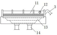
Fig. 1 is a schematic structural diagram of agricultural vegetable seedling raising equipment.
FIG. 2 is a schematic structural diagram of a vibration mechanism of the agricultural vegetable seedling raising device.
Fig. 3 is a schematic structural diagram of the placing groove of the agricultural vegetable seedling raising equipment.
Fig. 4 is a schematic structural diagram of the moving mechanism of the agricultural vegetable seedling raising equipment.
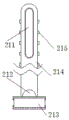
FIG. 5 is a schematic structural view of a crushing rod of the agricultural vegetable seedling raising equipment.
FIG. 6 is a schematic structural view of a sliding block of the agricultural vegetable seedling raising device of the present invention.
Fig. 7 is a schematic structural diagram of an agricultural vegetable seedling raising equipment striking device of the invention.
In the figure: the device comprises a vibration mechanism-1, a working platform-2, a transmission pipe-3, a machine body-4, a placing groove-11, a water inlet-12, a collecting groove-13, a chip removal pipe-14, a jet port-111, a movable mechanism-112, a filter screen layer-113, an embedding plate-114, a chip removal port-115, a crushing rod-121, a hollow plate-122, a connecting shaft-123, a sliding groove-124, a second sliding groove-211, a rotating shaft-212, a sliding block-213, a swinging rod-214, a crushing tooth-215, a copper plate-131, an embedding plate-132, a striking device-133, an embedding block-134, a magnetic ball-331, an embedding iron ball-332, a second embedding block-333, a movable groove-334 and a rubber block-335.
Detailed Description
The invention is further described below with reference to the accompanying drawings:
example 1:
as shown in figures 1 to 5:
the invention provides agricultural vegetable seedling raising equipment which structurally comprises a vibration mechanism 1, a working platform 2, a transmission pipe 3 and a machine body 4, wherein the vibration mechanism 1 is fixedly embedded above the machine body 4, the working platform 2 is embedded in the outer side surface of the upper end of the machine body 4, the transmission pipe 3 is connected to the outer side end surface of the vibration mechanism 1 in an embedded mode, and the transmission pipe 3 is connected to the end surface of the right side of the machine body 4 in an embedded and clamped mode; vibration mechanism 1 includes standing groove 11, water inlet 12, collecting vat 13, chip removal pipe 14, standing groove 11 inlays and locates directly over collecting vat 13, the inboard terminal surface at vibration mechanism 1 is installed to the block is inlayed to water inlet 12, collecting vat 13 is located water inlet 12 under, the lower extreme left and right sides at collecting vat 13 is installed to chip removal pipe 14 symmetry.
The placing groove 11 comprises an injection port 111, a movable mechanism 112, a filter screen layer 113, an embedding plate 114 and a chip removal port 115, wherein the injection port 111 is embedded in the left side surface of the upper end of the movable mechanism 112, the movable mechanism 112 is embedded in the right upper side of the filter screen layer 113, the chip removal port 115 is embedded and connected in the left side end surface and the right side end surface of the filter screen layer 113, the embedding plate 114 is embedded and installed in the outer side end surface of the movable mechanism 112, the chip removal port 115 is embedded in the lower end surface of the inner side of the embedding plate 114, the upper end surface of the filter screen layer 113 is in an arc-shaped contour with a high middle part and a low part, and small stones falling off from the movable mechanism 112 can be discharged outwards along the chip removal port 115.
Wherein, the moving mechanism 112 includes crushing pole 121, fretwork board 122, links up axle 123, spout 124, crushing pole 121 activity block is connecting links up axle 123, fretwork board 122 inlays and locates directly over spout 124, link up the medial surface that the moving mechanism 112 was evenly located to axle 123, the lower extreme lateral surface of crushing pole 121 is being connected to spout 124 activity block, crushing pole 121 surface is equipped with protruding fritter, can carry out the block to the stone that drops.
Wherein, crushing pole 121 includes second spout 211, pivot 212, sliding block 213, swinging arms 214, crushing tooth 215, the upper end lateral surface of crushing pole 121 is inlayed to second spout 211, the upper end lateral surface at sliding block 213 is installed to pivot 212 activity block, sliding block 213 is inlayed and is located crushing tooth 215 under, pivot 212 is being connected to the terminal surface activity block under the swinging arms 214, the outside terminal surface of swinging arms 214 is evenly located to crushing tooth 215, second spout 211 adopts the inlayer nested, and the inlayer profile is wrapping up linking axle 123, when making crushing pole 121 whole vibration, can make it use linking axle 123 to swing and slide as the center pivot.
The specific use mode and function of the embodiment are as follows:
in the invention, when in use, the agricultural seedlings needing to be separated and cleaned are placed on the placing groove 11 in the vibrating mechanism 1, then the equipment is started to spray water flow into the placing groove 11 along the conveying pipe 3 and the water inlet 12, the soil attached to the surface of the agricultural seedlings is peeled by utilizing the vibration of the placing groove 11 and the impact of the water flow, in order to avoid that larger stone particles attached to the soil fall into the moving mechanism 112 in the placing groove 11 to form clamping blockage along with peeling, the crushing rod 121 can be driven by the vibration of the placing groove 11 to swing along with the inertia force by taking the connecting shaft 123 as a central fulcrum, the connecting shaft 123 can slide in the second sliding groove 211 while swinging, and the longitudinal fixation is formed by the connecting state of the connecting shaft 213 and the sliding groove 124, so that the crushing rod 121 can repeatedly swing in the vibrating process of the placing groove 11, and the gap between the crushing rods 121 is continuously adjusted to discharge the stones outwards, and the outer side end face of the crushing rod 121 is uniformly provided with crushing teeth 215, when the crushing rod 121 swings, the crushing teeth 215 can extrude the embedded stones, so that the embedded angles of the falling stones are changed along with the continuously adjusted gaps, and the crushing teeth 215 are used for crushing the stones, so that the size of the stones is reduced, and the stones are easier to discharge.
Example 2:
as shown in fig. 6 to 7:
the sliding block 213 includes a copper plate 131, an embedded plate 132, an impact device 133, and an embedded block 134, the copper plate 131 is symmetrically installed at the left and right ends of the impact device 133, the copper plate 131 is connected to the embedded plate 132 in an embedded and clamped manner, the embedded block 134 is fixedly embedded at the outer end face of the impact device 133, the embedded block 134 is symmetrically installed at the left and right sides of the inner end of the embedded plate 132, the copper plate 131 and the embedded plate 132 are both made of steel with lower hardness and flexibility, and the impact device 133 can transmit vibration to the surface of the swing rod 214 when generating vibration.
The impact device 133 includes a magnetic ball 331, an embedded iron bead 332, a second embedded block 333, a movable groove 334, and a rubber block 335, wherein the magnetic ball 331 is symmetrically installed at the left end and the right end of the embedded iron bead 332, the embedded iron bead 332 is uniformly embedded in the inner side end face of the second embedded block 333, the second embedded block 333 is embedded in the inner side end face of the impact device 133, the movable groove 334 is embedded in the left end and the right end of the inner side of the impact device 133, the rubber block 335 is symmetrically installed at the left side and the right side of the magnetic ball 331, the embedded iron bead 332 is provided with four magnetic balls 331, the magnetic balls 331 at the two ends are opposite in magnetism, when the magnetic ball 331 at one end slides and impacts one end of the embedded iron bead 332, the embedded iron bead 332 whose other end is attached to the embedded iron bead 332 can be ejected outwards through the repulsive force between inertia and magnetism.
The specific use mode and function of the embodiment are as follows:
in the present invention, when the crushing rod 121 swings left and right along with the vibration of the placing slot 11, the sliding block 213 at the lower end of the crushing rod 121 will also drive the striking device 133 to swing along with the inertia, while the striking device 133 slides rapidly, the magnetic ball 331 located in the movable slot 334 will be driven to be adsorbed at one end of the embedded iron bead 332, while when swinging to the other direction, the magnetic ball 331 that is not adsorbed at the surface of the embedded iron bead 332 will be adsorbed at the surface of the embedded iron bead 332 rapidly along with the inertia, while the magnetic ball 331 at the left and right ends will change along with the four embedded iron beads 332 while being adsorbed, and along with the inertia generated by the rapid sliding, the magnetic ball 331 will impact on the embedded iron bead 332, while the magnetic ball 331 at the other end will be ejected outward rapidly, impact on the rubber block 335 to form vibration, so that the vibration is transmitted to the embedded plate 132 along with the copper plate 131, until it is transmitted to the surface of the oscillating rod 214, causing it to increase the pressing force of the crushing teeth 215 against the stones.
The technical solutions of the present invention or similar technical solutions designed by those skilled in the art based on the teachings of the technical solutions of the present invention are all within the scope of the present invention to achieve the above technical effects.
Claims (6)
1. An agricultural vegetable seedling raising device structurally comprises a vibration mechanism (1), a working platform (2), a transmission pipe (3) and a machine body (4), wherein the vibration mechanism (1) is fixedly embedded above the machine body (4), the working platform (2) is embedded in the outer side surface of the upper end of the machine body (4), the transmission pipe (3) is connected to the outer side end surface of the vibration mechanism (1) in a nested mode, and the end surface of the right side of the machine body (4) is embedded, clamped and connected with the transmission pipe (3); the method is characterized in that:
vibration mechanism (1) includes standing groove (11), water inlet (12), collecting vat (13), chip removal pipe (14), standing groove (11) are inlayed and are located collecting vat (13) directly over, the block is inlayed in water inlet (12) and install the medial surface at vibration mechanism (1), collecting vat (13) are located water inlet (12) under, the lower extreme left and right sides at collecting vat (13) is installed to chip removal pipe (14) symmetry.
2. An agricultural vegetable seedling raising apparatus as set forth in claim 1, wherein: the placing groove (11) comprises a jet orifice (111), a movable mechanism (112), a filter screen layer (113), an embedding plate (114) and a chip removal port (115), wherein the jet orifice (111) is embedded in the left side surface of the upper end of the movable mechanism (112), the movable mechanism (112) is embedded in the right upper side of the filter screen layer (113), the chip removal port (115) is embedded and connected with the end surfaces of the left side and the right side of the filter screen layer (113), the embedding plate (114) is embedded and fixedly installed on the end surface of the outer side of the movable mechanism (112), and the chip removal port (115) is embedded in the lower end surface of the inner side of the embedding plate (114).
3. An agricultural vegetable seedling raising apparatus as set forth in claim 2, wherein: the movable mechanism (112) comprises a crushing rod (121), a hollow plate (122), a connecting shaft (123) and a sliding groove (124), the crushing rod (121) is movably clamped and connected with the connecting shaft (123), the hollow plate (122) is embedded and arranged right above the sliding groove (124), the connecting shaft (123) is uniformly arranged on the inner side end face of the movable mechanism (112), and the sliding groove (124) is movably clamped and connected with the outer side face of the lower end of the crushing rod (121).
4. An agricultural vegetable seedling raising apparatus as set forth in claim 3, wherein: crushing pole (121) include second spout (211), pivot (212), sliding block (213), swinging arms (214), smash tooth (215), the upper end lateral surface of smashing pole (121) is inlayed and is located in second spout (211), pivot (212) activity block is installed at the upper end lateral surface of sliding block (213), sliding block (213) are inlayed and are located crushing tooth (215) under, pivot (212) are being connected to terminal surface activity block under swinging arms (214), the outside terminal surface of swinging arms (214) is evenly located in crushing tooth (215).
5. An agricultural vegetable seedling raising apparatus as set forth in claim 4, wherein: sliding block (213) include copper (131), mosaic plate (132), ram (133), inlay solid piece (134), both ends about ram (133) are installed to copper (131) symmetry, copper (131) are being connected in mosaic plate (132) inlay block, ram (133) outside terminal surface inlays and links firmly and inlays solid piece (134) next, inlay solid piece (134) symmetry is installed in the inner left and right sides of mosaic plate (132).
6. An agricultural vegetable seedling raising apparatus as set forth in claim 5, wherein: percussion device (133) are including magnetism ball (331), the embedded iron pearl (332), second embedded block (333), activity groove (334), rubber block (335), magnetism ball (331) symmetry is installed at the left and right sides both ends of embedded iron pearl (332), embedded iron pearl (332) evenly inlays the medial surface of locating second embedded block (333), the inboard terminal surface of block (333) is inlayed and is blocked at percussion device (133) is inlayed in second embedded block (333), both ends about the inboard of percussion device (133) are inlayed and locate in activity groove (334), the left and right sides at magnetism ball (331) is installed to rubber block (335) symmetry.
Priority Applications (1)
| Application Number | Priority Date | Filing Date | Title |
|---|---|---|---|
| CN202110157690.1A CN112753424A (en) | 2021-02-05 | 2021-02-05 | Agricultural vegetable seedling raising equipment |
Applications Claiming Priority (1)
| Application Number | Priority Date | Filing Date | Title |
|---|---|---|---|
| CN202110157690.1A CN112753424A (en) | 2021-02-05 | 2021-02-05 | Agricultural vegetable seedling raising equipment |
Publications (1)
| Publication Number | Publication Date |
|---|---|
| CN112753424A true CN112753424A (en) | 2021-05-07 |
Family
ID=75704960
Family Applications (1)
| Application Number | Title | Priority Date | Filing Date |
|---|---|---|---|
| CN202110157690.1A Withdrawn CN112753424A (en) | 2021-02-05 | 2021-02-05 | Agricultural vegetable seedling raising equipment |
Country Status (1)
| Country | Link |
|---|---|
| CN (1) | CN112753424A (en) |
Citations (4)
| Publication number | Priority date | Publication date | Assignee | Title |
|---|---|---|---|---|
| CN206604812U (en) * | 2017-02-28 | 2017-11-03 | 四川建筑职业技术学院 | A kind of natural sand clay content cleaning machine |
| CN209061713U (en) * | 2018-11-05 | 2019-07-05 | 四川农业大学 | A kind of dendrobium seedling washing machine |
| CN211412262U (en) * | 2019-11-13 | 2020-09-04 | 广东南工机械集团有限公司 | Stone soil filter equipment |
| CN211587677U (en) * | 2019-12-02 | 2020-09-29 | 云南农业大学 | Gastrodia elata belt cleaning device |
-
2021
- 2021-02-05 CN CN202110157690.1A patent/CN112753424A/en not_active Withdrawn
Patent Citations (4)
| Publication number | Priority date | Publication date | Assignee | Title |
|---|---|---|---|---|
| CN206604812U (en) * | 2017-02-28 | 2017-11-03 | 四川建筑职业技术学院 | A kind of natural sand clay content cleaning machine |
| CN209061713U (en) * | 2018-11-05 | 2019-07-05 | 四川农业大学 | A kind of dendrobium seedling washing machine |
| CN211412262U (en) * | 2019-11-13 | 2020-09-04 | 广东南工机械集团有限公司 | Stone soil filter equipment |
| CN211587677U (en) * | 2019-12-02 | 2020-09-29 | 云南农业大学 | Gastrodia elata belt cleaning device |
Similar Documents
| Publication | Publication Date | Title |
|---|---|---|
| CN109500073B (en) | Efficient soil remediation method | |
| CN107996117B (en) | Winter Potato Vibrating Digging Harvester | |
| CN101766081A (en) | Pull-type combined harvester for deep-root Chinese medicinal plants | |
| CN104855036A (en) | Harvesting device capable of realizing layered collection and soil removal | |
| CN111139783B (en) | Ocean beach purification garbage cleaning device | |
| CN118020440B (en) | Small-size agricultural ditching device suitable for mountain area hills | |
| CN105027710B (en) | A kind of farmland clear stone machine of working soil | |
| CN105027802B (en) | Crawler-type water chestnut excavator | |
| CN207786768U (en) | A kind of Preliminary working device of aluminum ore | |
| CN212975854U (en) | Impurity removing device for coffee bean pretreatment | |
| CN2490799Y (en) | Field cleaning and soil prepn. machine | |
| CN118104426A (en) | Soil turning device and soil turning method for planting milk vetch | |
| CN110152997A (en) | A kind of automatic mixed screen device of corundum powder production | |
| CN104290039A (en) | Cleaning device of alloy steel boat and cleaning method thereof | |
| CN205761689U (en) | Talc Ore washing equipment vibrating device | |
| CN217241293U (en) | Novel forestry operation is with making ground soil preparation machine | |
| CN106376259B (en) | A kind of sand separation fertilization all-in-one machine | |
| CN117738157A (en) | Excavation component and heavy metal contaminated soil restoration and treatment device | |
| RU2436277C2 (en) | Potato harvester | |
| CN206323753U (en) | An all-in-one machine for sand and soil separation and fertilization | |
| CN208691731U (en) | One kind prevents adhesion rice seedling thrower | |
| CN203542387U (en) | Alloy steel boat cleaning device | |
| CN116391475A (en) | Peeler for seedling cultivation of sweet potato seeds and application method thereof | |
| CN204652890U (en) | The clear stone soil preparation machine in a kind of farmland | |
| CN108521972A (en) | Water chestnut digger |
Legal Events
| Date | Code | Title | Description |
|---|---|---|---|
| PB01 | Publication | ||
| PB01 | Publication | ||
| SE01 | Entry into force of request for substantive examination | ||
| SE01 | Entry into force of request for substantive examination | ||
| WW01 | Invention patent application withdrawn after publication | ||
| WW01 | Invention patent application withdrawn after publication |
Application publication date: 20210507 |