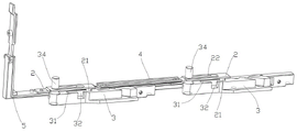
Door and window cantilever locking mechanism
Technical Field
The invention relates to a door and window structure, in particular to a door and window cantilever locking mechanism.
Background
The hardware fittings of the inner-falling door and window mainly comprise three parts, namely an upper cantilever, a lower cantilever and a transmission mechanism. The three states of the translational inverted window are as follows:
1) locking state: the upper cantilever and the lower cantilever are closed, and the lock point of the transmission mechanism is matched with the lock seat to lock the fan on the frame;
2) a translation state: the upper cantilever and the lower cantilever are both opened, at the moment, the fan is separated from the frame, and the fan can slide on the track of the frame;
3) inverted (suspended) state: the cantilever on the upper part is opened, the cantilever on the lower part is closed, at the moment, the fan and the frame form a certain included angle, the upper part is ventilated, and the fan cannot slide.
The three states of the inward-falling door and window do not allow the lower cantilever to be opened when the inward-falling door and window are turned inwards or locked. Referring to fig. 1, the inward-falling state is mainly realized by the cooperation of the locking point 21 on the sash 10 and the locking seat 40 on the frame, that is, the lower part of the sash 10 is locked, and the upper part is opened, but the locking is only the inward-falling locking, because the lower frame 30 cannot be simultaneously provided with the inward-falling locking point and the transmission locking point, when the sash 10 is in the fully-closed state, there is no locking point for locking between the lower frame 30 and the sash 10, and the safety and the sealing performance are poor. The lower part of the existing translation window is open and is provided with a transmission part, a notch of a hardware is not installed, the lock seat cannot be installed to increase the inward falling function, and structural transformation and use of doors and windows are limited.
Disclosure of Invention
In order to solve the problems, the invention provides a door and window cantilever locking mechanism, wherein a transmission rod is provided with a locking point and is matched with a translational sliding mechanism to realize the function of inward falling (upward suspension), and the additional space on a fan or a frame is not occupied. The technical scheme adopted by the invention is as follows:
a door and window cantilever locking mechanism comprises at least one cantilever and at least one locking rod arranged in a sash; the lock rod is controlled by the handle of the door and window to slide in the sash, one end of the cantilever is in sliding fit with the lock rod, and the other end of the cantilever is hinged on the frame or the frame sliding mechanism;
the lock rod is fixedly provided with lock points, the cantilever is provided with a strip-shaped groove, the middle part of the groove is provided with an opening, and the lock points are correspondingly arranged in the groove one by one and can slide or separate in the groove; when the locking point slides to one end of the groove, the fan is in a locking state; when the locking point slides to the opening of the groove, the locking point can be separated from the groove, the cantilever can rotate, and the fan can be opened; when the locking point slides to the other end of the groove, the fan is in an inward-falling state.
According to the door and window cantilever locking mechanism, the lock rod is provided with the elongated sliding hole, one end of the cantilever is provided with the limiting pin, and the limiting pin can be inserted into the sliding hole in a sliding mode.
According to the door and window cantilever locking mechanism, the number of the cantilevers and the number of the locking rods are two respectively, the cantilevers and the locking rods are matched in a one-to-one correspondence mode, and the two locking rods are in transmission connection through the transmission rod.
The cantilever locking mechanism of the door and window can be arranged in the sash frame at the upper part of the door and window or/and the sash frame at the lower part of the door and window.
The invention has the beneficial effects that: according to the cantilever locking mechanism, a locking point and a 'locking seat' (a cantilever groove) are integrated on an original transmission mechanism of a translation window, the space of a fan or a frame is not additionally occupied, the structure is compact, and the locking point has multiple functions; the locking point slides along with the locking rod, the position of the locking point in the cantilever groove can be controlled, the opening and closing and inward-falling states of the fan are corresponded, and the safety and the tightness of the fan during locking are guaranteed. To the translation or flat-open door and window of current area cantilever, can realize transforming through seting up the recess on the cantilever and set up locking lever and lock point, increase the interior function of falling, practice thrift the cost.
Drawings
Fig. 1 is a schematic structural view of an inverted window in the prior art in an inverted state.
FIG. 2 is a schematic structural view of a transmission mechanism in a door/window locking state according to an embodiment of the present invention;
FIG. 3 is a schematic view of a locking point in a locked state of a door/window according to an embodiment of the present invention;
FIG. 4 is a schematic structural diagram of a transmission mechanism in a side-hung (push-pull) state of a door/window according to an embodiment of the present invention;
FIG. 5 is a schematic view of a lock point in a side-hung (push-pull) state of a door/window according to an embodiment of the present invention;
FIG. 6 is a schematic structural view of the cantilever fully opened in the side-hung (push-pull) state of the door/window according to the embodiment of the present invention;
FIG. 7 is a schematic structural view of a transmission mechanism in a door/window falling state according to an embodiment of the present invention;
FIG. 8 is a schematic view of a locking point in a door/window in an inverted state according to an embodiment of the present invention.
In the figure: 1. a slide bar; 2. a lock lever; 3. a cantilever; 4. a transmission rod; 5. an angle driver; 6. a transmission box; 7. a handle; 21. locking points; 22. a slide hole; 31. a locking end; 32. an opening; 33. an inner inverted end; 34. a spacing pin; 10. a fan; 20. an upper frame; 30. a lower frame; 40. and (4) a lock seat.
Detailed Description
The invention is further explained below with reference to the drawings.
The embodiment relates to a door and window cantilever locking mechanism capable of being applied to translation inner-falling, and can also be applied to other structures such as inner-opening inner-falling doors and windows, outer-opening lower-suspension doors and windows. The cantilever locking mechanism comprises at least one cantilever 3 and at least one locking bar 2 mounted within the sash. In this embodiment, there are two cantilevers 3 and two lock levers 2, the cantilevers 3 and the lock levers 2 are matched in a one-to-one correspondence manner, and the two lock levers 2 are in transmission connection through a transmission rod 4.
The lock rod 2 is controlled by a handle 7 of a door and window in a transmission mode to slide in the sash, a long strip-shaped sliding hole 22 is formed in the lock rod 2, a limiting pin 34 is arranged at one end of the cantilever 3, the limiting pin 34 can be inserted into the sliding hole 22 in a sliding mode, and the other end of the cantilever 3 is hinged to the frame or a sliding rod 1 of the sliding mechanism in the frame. The sliding mechanism can refer to the scheme of patent application No. 2020115095052 'a push-pull sliding mechanism and a door window'.
The locking rod 2 is fixedly provided with locking points 21, the cantilever 3 is provided with a strip-shaped groove, the middle part of the groove is provided with an opening 32, and the locking points 21 are arranged in the groove in a one-to-one correspondence manner and can slide or break away in the groove.
The closing, opening and falling states of the door and window are described in detail with reference to the accompanying drawings 2 to 8:
locking state of fan: with reference to fig. 2 and 3, the handle of the handle 7 is downward, the locking point 21 is limited at the left end of the groove of the cantilever 3, namely the locking end 31, the cantilever 3 cannot be rotated to be opened, the upper part and the lower part of the fan are both pressed on the frame to be in a locking state, and the locking point 21 improves the sealing property and the safety of the fan during locking.
Openable state of the fan: with reference to fig. 4 to 6, the handle of the handle 7 is rotated to the horizontal direction, and the lock rod 2 connected to the angle driver 5 slides in the sash through the transmission of the transmission box 6 and the angle driver 5, so as to drive the lock point 21 to slide to the opening 32 of the groove, at this time, the lock point 21 can be separated from the groove of the cantilever 3, the cantilever 3 can freely rotate to be in a flat-open state, and the upper part and the lower part of the sash are both in an open state. If a sliding rod 1 capable of sliding is arranged in the frame, the sash can be pushed and pulled to slide left and right after being opened.
③ the inner-falling state of the fan: combine fig. 7 and 8, the handle of handle 7 is for upwards, through the transmission of transmission box 6 and angle drive ware 5, locking lever 2 slides to the right in the fan to drive lock point 21 and slide to interior back end 33 department from the opening 32 of recess right, lock point 21 is injectd in interior back end 33 department, and cantilever 3 can't be opened, and the lower part of fan can't be opened, upper portion is opened, and the fan is the state of falling in.