CN112743774A - Injection mold convenient for internal thread demolding and operation method - Google Patents
Injection mold convenient for internal thread demolding and operation method Download PDFInfo
- Publication number
- CN112743774A CN112743774A CN202110122103.5A CN202110122103A CN112743774A CN 112743774 A CN112743774 A CN 112743774A CN 202110122103 A CN202110122103 A CN 202110122103A CN 112743774 A CN112743774 A CN 112743774A
- Authority
- CN
- China
- Prior art keywords
- plate
- mounting
- injection
- mounting plate
- gear
- Prior art date
- Legal status (The legal status is an assumption and is not a legal conclusion. Google has not performed a legal analysis and makes no representation as to the accuracy of the status listed.)
- Pending
Links
- 238000002347 injection Methods 0.000 title claims abstract description 72
- 239000007924 injection Substances 0.000 title claims abstract description 72
- 238000000034 method Methods 0.000 title claims abstract description 10
- 238000000465 moulding Methods 0.000 claims abstract description 30
- 239000000463 material Substances 0.000 claims abstract description 29
- 238000001816 cooling Methods 0.000 claims abstract description 19
- 238000001746 injection moulding Methods 0.000 claims abstract description 16
- 238000007493 shaping process Methods 0.000 claims description 25
- 238000009434 installation Methods 0.000 claims description 14
- 230000006872 improvement Effects 0.000 abstract description 13
- 230000005540 biological transmission Effects 0.000 description 7
- 230000007246 mechanism Effects 0.000 description 3
- 210000003437 trachea Anatomy 0.000 description 3
- 238000005516 engineering process Methods 0.000 description 2
- 230000007812 deficiency Effects 0.000 description 1
- 238000004519 manufacturing process Methods 0.000 description 1
- 238000012986 modification Methods 0.000 description 1
- 230000004048 modification Effects 0.000 description 1
- 238000011017 operating method Methods 0.000 description 1
- 239000000243 solution Substances 0.000 description 1
Images



Classifications
-
- B—PERFORMING OPERATIONS; TRANSPORTING
- B29—WORKING OF PLASTICS; WORKING OF SUBSTANCES IN A PLASTIC STATE IN GENERAL
- B29C—SHAPING OR JOINING OF PLASTICS; SHAPING OF MATERIAL IN A PLASTIC STATE, NOT OTHERWISE PROVIDED FOR; AFTER-TREATMENT OF THE SHAPED PRODUCTS, e.g. REPAIRING
- B29C45/00—Injection moulding, i.e. forcing the required volume of moulding material through a nozzle into a closed mould; Apparatus therefor
- B29C45/17—Component parts, details or accessories; Auxiliary operations
- B29C45/26—Moulds
- B29C45/2618—Moulds having screw-threaded mould walls
- B29C45/262—Moulds having screw-threaded mould walls provided with unscrewing drive means
-
- B—PERFORMING OPERATIONS; TRANSPORTING
- B29—WORKING OF PLASTICS; WORKING OF SUBSTANCES IN A PLASTIC STATE IN GENERAL
- B29C—SHAPING OR JOINING OF PLASTICS; SHAPING OF MATERIAL IN A PLASTIC STATE, NOT OTHERWISE PROVIDED FOR; AFTER-TREATMENT OF THE SHAPED PRODUCTS, e.g. REPAIRING
- B29C45/00—Injection moulding, i.e. forcing the required volume of moulding material through a nozzle into a closed mould; Apparatus therefor
- B29C45/17—Component parts, details or accessories; Auxiliary operations
- B29C45/26—Moulds
- B29C45/2602—Mould construction elements
-
- B—PERFORMING OPERATIONS; TRANSPORTING
- B29—WORKING OF PLASTICS; WORKING OF SUBSTANCES IN A PLASTIC STATE IN GENERAL
- B29C—SHAPING OR JOINING OF PLASTICS; SHAPING OF MATERIAL IN A PLASTIC STATE, NOT OTHERWISE PROVIDED FOR; AFTER-TREATMENT OF THE SHAPED PRODUCTS, e.g. REPAIRING
- B29C45/00—Injection moulding, i.e. forcing the required volume of moulding material through a nozzle into a closed mould; Apparatus therefor
- B29C45/17—Component parts, details or accessories; Auxiliary operations
- B29C45/26—Moulds
- B29C45/2602—Mould construction elements
- B29C45/2606—Guiding or centering means
-
- B—PERFORMING OPERATIONS; TRANSPORTING
- B29—WORKING OF PLASTICS; WORKING OF SUBSTANCES IN A PLASTIC STATE IN GENERAL
- B29C—SHAPING OR JOINING OF PLASTICS; SHAPING OF MATERIAL IN A PLASTIC STATE, NOT OTHERWISE PROVIDED FOR; AFTER-TREATMENT OF THE SHAPED PRODUCTS, e.g. REPAIRING
- B29C45/00—Injection moulding, i.e. forcing the required volume of moulding material through a nozzle into a closed mould; Apparatus therefor
- B29C45/17—Component parts, details or accessories; Auxiliary operations
- B29C45/26—Moulds
- B29C45/27—Sprue channels ; Runner channels or runner nozzles
- B29C45/2725—Manifolds
-
- B—PERFORMING OPERATIONS; TRANSPORTING
- B29—WORKING OF PLASTICS; WORKING OF SUBSTANCES IN A PLASTIC STATE IN GENERAL
- B29C—SHAPING OR JOINING OF PLASTICS; SHAPING OF MATERIAL IN A PLASTIC STATE, NOT OTHERWISE PROVIDED FOR; AFTER-TREATMENT OF THE SHAPED PRODUCTS, e.g. REPAIRING
- B29C45/00—Injection moulding, i.e. forcing the required volume of moulding material through a nozzle into a closed mould; Apparatus therefor
- B29C45/17—Component parts, details or accessories; Auxiliary operations
- B29C45/40—Removing or ejecting moulded articles
- B29C45/4005—Ejector constructions; Ejector operating mechanisms
-
- B—PERFORMING OPERATIONS; TRANSPORTING
- B29—WORKING OF PLASTICS; WORKING OF SUBSTANCES IN A PLASTIC STATE IN GENERAL
- B29C—SHAPING OR JOINING OF PLASTICS; SHAPING OF MATERIAL IN A PLASTIC STATE, NOT OTHERWISE PROVIDED FOR; AFTER-TREATMENT OF THE SHAPED PRODUCTS, e.g. REPAIRING
- B29C45/00—Injection moulding, i.e. forcing the required volume of moulding material through a nozzle into a closed mould; Apparatus therefor
- B29C45/17—Component parts, details or accessories; Auxiliary operations
- B29C45/72—Heating or cooling
- B29C45/73—Heating or cooling of the mould
- B29C45/7337—Heating or cooling of the mould using gas or steam
Landscapes
- Engineering & Computer Science (AREA)
- Manufacturing & Machinery (AREA)
- Mechanical Engineering (AREA)
- Moulds For Moulding Plastics Or The Like (AREA)
Abstract
The invention discloses an injection mould convenient for internal thread demoulding and an operation method thereof. The invention operates after improvement; the injection molding machine pushes the upper die base plate to slide, the upper die plate and the lower die plate are folded and continue to slide downwards until the molding stripping block rises to the maximum stroke, the injection molding machine injects materials into the pouring gate, the materials are injected into the molding cavity for molding, after cooling, the upper die and the lower die are separated, and meanwhile, the first cylinder drives the molding stripping block to rotate to screw out the part. The invention has reasonable design, after the part is formed, the upper die and the lower die are separated, and simultaneously, the cylinder pushes the forming demoulding block to rotate, so that the part is screwed out of the forming cavity, and the part and the die are quickly demoulded.
Description
Technical Field
The invention relates to the technical field related to mechanical dies, in particular to an injection mold convenient for internal thread demolding and an operation method.
Background
The demolding device is an essential component for realizing automatic production of the injection mold, and the demolding device of the general injection mold directly ejects and demolds a plastic part by utilizing an ejector pin or an ejector plate. However, demolding of threaded molded parts is no longer suitable for the conventional direct-ejection demolding due to the presence of the thread structure.
The invention of application number CN201810245226.6 discloses an internal thread part injection mold for rotary demolding, which comprises a movable mold, a fixed mold is arranged above the movable mold, a mold core is arranged on the movable mold, a mold cavity is arranged in the mold core, a rotary demolding thread core is arranged in the fixed mold, the rotary demolding thread core comprises a plurality of external thread core cylinders, each external thread core cylinder comprises a thread insert at the lower end and a rotary demolding transmission end at the upper end, the thread insert downwards extends into the mold cavity of the mold core to form an internal thread part molding space, the rotary demolding transmission end is in gear transmission connection with a gear transmission device, the rotary transmission end is internally lined with a fixed external thread guide pillar, and the gear transmission device drives the external thread core cylinder to upwards rotate and demold along the external thread guide pillar through the rotary demolding transmission.
The invention of application No. CN201210041832.9 provides an internal thread demolding mechanism for demolding a product having an internal thread when molding the product. The internal thread demoulding mechanism comprises a sleeve and a sleeve core. The sleeve comprises a plurality of elastic sleeve legs and a cylindrical sleeve body which is connected with the plurality of sleeve legs. Each leg has an external thread at one end for forming an internal thread of a product together with the core. The sleeve core comprises a core pin and a cylindrical core body connected with the core pin. The core leg includes a central portion and a plurality of projections projecting from the central portion at uniform intervals. The diameter of the core body is smaller than that of the sleeve body. The sleeve is sleeved on the sleeve core in a one-way sliding manner, and the front end of the sleeve foot is flush with the front end of the core foot. The sleeve slides along the sleeve core after being pushed by external force, and after the core pin is separated from the external thread of the sleeve pin, the sleeve pins are elastically deformed by the external force to separate the external thread from the internal thread.
The invention of application number CN201710618990.9 discloses a demoulding mechanism for an internal thread part with a back-off, which comprises an elastic plate, a top plate, a main shaft, a thread shaft, an inner rod and a mounting plate; the mounting plate, the elastic plate and the top plate are arranged oppositely in sequence from top to bottom, a gap exists between every two elastic plates, and top extension springs are arranged at four corners of the bottom of each elastic plate; the main shaft penetrates through the top plate and the elastic plate from the bottom to reach the top of the mounting plate and is connected with a driving gear; the threaded shaft is provided with two symmetrical driven gears which are arranged on two sides of the driving gear, and the top of the threaded shaft is provided with a driven gear meshed with the driving gear; the inner rod vertically penetrates through the threaded shaft and extends downwards, the inner rod comprises a core rod and a sleeve rod sleeved on the periphery of the core rod, the core rod is provided with an inclination block, and the sleeve rod is provided with a sliding block clamped with the inclination block. The invention effectively protects the internal thread and the back-off of the product through the step-by-step demoulding design, has simple structure and is worth popularizing and using.
However, the conventional technology of forming the thread by using the slider part, separating the slider for forming the thread from the plastic part in advance before ejecting, ejecting and demolding the plastic part is relatively suitable for demolding the plastic part with the external thread, but for the plastic part with the internal thread, the internal slider for forming the internal thread needs to be separated from the internal thread of the plastic part in advance to eject and demold, so that the technology cannot be well suitable for demolding the small plastic part with the internal thread.
Disclosure of Invention
Accordingly, to address the above-described deficiencies, the present invention provides an injection mold and method of operation that facilitates demolding of internal threads; the invention operates after improvement; the injection molding machine pushes the upper die base plate to slide, the upper die plate and the lower die plate are folded and continue to slide downwards until the molding stripping block rises to the maximum stroke, the injection molding machine injects materials into the pouring gate, the materials are injected into the molding cavity for molding, after cooling, the upper die and the lower die are separated, and meanwhile, the first cylinder drives the molding stripping block to rotate to screw out the part. The invention has reasonable design, after the part is formed, the upper die and the lower die are separated, and simultaneously, the cylinder pushes the forming demoulding block to rotate, so that the part is screwed out of the forming cavity, and the part and the die are quickly demoulded.
The invention is realized by constructing the injection mould which is convenient for demoulding the internal thread; the injection mould comprises a lower mould bottom plate;
the injection mould also comprises a pair of first cushion blocks which are fixedly arranged on two sides of the upper end surface of the lower mould bottom plate;
the injection mould also comprises a first mounting plate which is fixedly mounted on the upper end surfaces of the two first cushion blocks;
the injection mould also comprises a fourth mounting plate which is arranged on the side surface of the first mounting plate;
the injection mould also comprises a first cylinder which is arranged on the end surface of the fourth mounting plate far away from the first mounting plate;
the injection mould also comprises a mounting seat which is arranged between the two cushion blocks and is fixedly arranged on the upper end surface of the lower mould bottom plate;
the injection mould also comprises a second mounting plate which is fixedly arranged on the upper end surface of the first mounting plate;
the injection mould also comprises a third mounting plate which is fixedly arranged on the upper end surface of the second mounting plate;
the injection mould also comprises a plurality of forming demoulding blocks which are rotatably connected with the upper end surface of the fourth mounting plate; the first cylinder drives the forming demoulding block to rotate; the top of the forming demolding block is provided with a thread; the lower part of the threaded section of the forming demolding block is in a round table shape;
the injection mould also comprises a lower template which is connected above the third mounting plate in a sliding way; the forming demoulding block is matched with the lower template forming cavity;
the injection mould also comprises an upper template which is connected above the lower template in a sliding way;
the injection mould also comprises a first base plate which is fixedly arranged on the upper end surface of the upper mould plate; a first mounting cavity is formed in the first base plate;
the injection mould also comprises a runner which is arranged in the first mounting cavity and communicated with the upper template forming cavity;
the injection mould also comprises an upper mould base plate which is fixedly arranged on the upper end surface of the first base plate; the sub-runners are connected with the upper template, the first base plate and the upper die base plate in a sliding manner;
the injection mould also comprises a pouring gate which is arranged on the upper end surface of the upper mould base plate and communicated with the sub-runner.
As an improvement of the technical scheme, the injection mold is convenient for demolding the internal thread; a mounting seat is arranged between the first cushion blocks and fixedly mounted on the upper end surface of the lower die bottom plate, a rack is connected with the first air cylinder and is in sliding connection with the mounting seat, a first gear is arranged between the two cushion blocks and is in rotating connection with the lower die bottom plate, and the rack is matched with the first gear;
a second mounting cavity is formed in the second mounting plate, a third gear is arranged in the second mounting cavity, and the third gear is connected with the first gear through a shaft;
the shaping drawing of patterns piece lower extreme runs through third mounting panel and second installation cavity and is connected with the rotation of first mounting panel, the shaping takes off the module and installs the second gear in second installation cavity section, second gear and third gear engagement.
As an improvement of the technical scheme, the injection mold is convenient for demolding the internal thread; a plurality of second guide rods are arranged between the fourth mounting plate and the first mounting plate, the fourth mounting plate is fixedly connected with the second guide rods, a sliding plate is sleeved outside the second guide rods and is connected with the second guide rods in a sliding mode, the sliding plate is connected with a piston rod of the first cylinder, and the sliding plate is connected with the rack in a maintaining mode.
As an improvement of the technical scheme, the injection mold is convenient for demolding the internal thread; the upper end face of the third mounting plate is fixedly provided with a plurality of first guide rods, the lower template is connected with the first guide rods in a sliding mode, and the upper template is connected with the first guide rods in a sliding mode.
As an improvement of the technical scheme, the injection mold is convenient for demolding the internal thread; and a plurality of buffer rods are arranged between the lower template and the third mounting plate.
As an improvement of the technical scheme, the injection mold is convenient for demolding the internal thread; the improved forming die comprises an upper die plate and is characterized in that an air inlet is formed in the side face of the upper die plate and communicated with an upper die plate forming cavity, the upper die plate forming cavity is communicated with the upper die plate forming cavity through an air pipe, an air outlet is formed in one side of the air inlet, and the air outlet is communicated with the upper die plate forming cavity.
As an improvement of the technical scheme, the injection mold is convenient for demolding the internal thread; the material injection pipe is arranged at the discharge port of the sub-runner and is in sliding connection with the first base plate and the upper die plate, and a spring is sleeved outside the material injection pipe.
An operating method of an injection mould for facilitating demoulding of internal threads as described above; the injection molding machine pushes the upper die base plate to slide, the upper die plate and the lower die plate are folded and continue to slide downwards until the molding stripping block rises to the maximum stroke, the injection molding machine injects materials into the pouring gate, the materials are injected into the molding cavity for molding, after cooling, the upper die and the lower die are separated, and meanwhile, the first cylinder drives the molding stripping block to rotate to screw out the part.
The invention has the following advantages: the invention provides an injection mould convenient for demoulding of internal threads by improvement; the method has the following improvements and advantages;
the invention comprises a lower die bottom plate, a pair of first cushion blocks are fixedly arranged on two sides of the upper end surface of the lower die bottom plate; the invention also comprises a first mounting plate fixedly arranged on the upper end surfaces of the two first cushion blocks, a fourth mounting plate arranged on the side surface of the first mounting plate, a first cylinder arranged on the end surface of the fourth mounting plate far away from the first mounting plate, a mounting seat arranged between the two cushion blocks and fixedly arranged on the upper end surface of the lower die bottom plate, a second mounting plate fixedly arranged on the upper end surface of the first mounting plate, a third mounting plate fixedly arranged on the upper end surface of the second mounting plate, a plurality of forming demoulding blocks rotatably connected with the upper end surface of the fourth mounting plate, a forming demoulding block driven by the first cylinder to rotate, threads processed on the top of the forming demoulding block, a circular truncated cone shape below the thread section of the forming demoulding block, and a lower die plate slidably connected above the third mounting plate, the forming demolding device comprises a forming demolding module, an upper template, a first base plate, a runner, an upper template forming cavity, a first mounting cavity, a runner and a runner, wherein the forming demolding module is matched with the forming cavity of the lower template, the upper template is connected above the lower template in a sliding mode, the first base plate is fixedly mounted on the upper end face of the upper template, the first mounting cavity is formed in the first base plate, the runner is arranged in the first mounting cavity and communicated with the forming cavity of the upper template, the upper template is fixedly mounted on the upper end face of the first base plate, the runner is connected with the upper template, the first base plate and the upper template in a sliding mode, and the runner is arranged on the upper end.
2, when the invention is operated; the injection molding machine pushes the upper die base plate to slide, the upper die plate and the lower die plate are folded and continue to slide downwards until the molding stripping block rises to the maximum stroke, the injection molding machine injects materials into the pouring gate, the materials are injected into the molding cavity for molding, after cooling, the upper die and the lower die are separated, and meanwhile, the first cylinder drives the molding stripping block to rotate to screw out the part. The invention has reasonable design, after the part is formed, the upper die and the lower die are separated, and simultaneously, the cylinder pushes the forming demoulding block to rotate, so that the part is screwed out of the forming cavity, and the part and the die are quickly demoulded.
3, in the embodiment of the present invention, a mounting seat is disposed between the two cushion blocks, and is fixedly mounted on the upper end surface of the lower mold bottom plate, a rack is connected to the first cylinder, the rack is slidably connected to the mounting seat, a first gear is disposed between the two cushion blocks, and is rotatably connected to the lower mold bottom plate, and the rack is kept engaged with the first gear. A second mounting cavity is formed in the second mounting plate, a third gear is arranged in the second mounting cavity, and the third gear is connected with the first gear through a shaft; the shaping drawing of patterns piece lower extreme runs through third mounting panel and second installation cavity and is connected with the rotation of first mounting panel, the shaping takes off the module and installs the second gear in second installation cavity section, second gear and third gear engagement.
And 4, a plurality of second guide rods are arranged between the fourth mounting plate and the first mounting plate, the fourth mounting plate is fixedly connected with the second guide rods, a sliding plate is sleeved outside the plurality of second guide rods and is slidably connected with the second guide rods, the sliding plate is connected with the piston rod of the first cylinder, and the sliding plate is connected with the rack. The rack drives the first gear to rotate, the third gear which is coaxial with the first gear rotates along with the first gear, the second gear is driven to rotate, and the forming demolding block rotates along with the second gear.
According to the embodiment of the invention, a plurality of first guide rods are fixedly mounted on the upper end surface of the third mounting plate, the lower template is connected with the first guide rods in a sliding manner, and the upper template is connected with the first guide rods in a sliding manner. The movement of the upper template and the lower template is guided, and the movement precision is improved.
6, in the embodiment of the invention, the discharge port of the sub-runner is provided with a material injection pipe, the material injection pipe is connected with the first base plate and the upper die plate in a sliding manner, and a spring is sleeved outside the material injection pipe.
And 7, furthermore, a plurality of buffer rods are arranged between the lower die plate and the third mounting plate, so that the vibration generated when the upper die and the lower die are closed is relieved, and the stability of the die is improved.
And 8, the cope match-plate pattern side sets up an air inlet, air inlet and cope match-plate pattern become die cavity intercommunication, through the trachea intercommunication between the cope match-plate pattern becomes die cavity, air inlet one side sets up a gas outlet, gas outlet and cope match-plate pattern become die cavity intercommunication, among the part cooling shaping process, let in cold air to the shaping intracavity for the shaping speed of part improves cooling efficiency. Reasonable design air inlet and gas outlet, part cooling forming in-process lets in cold air to the shaping intracavity for the shaping speed of part improves cooling efficiency.
Drawings
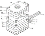
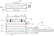
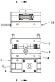
FIGS. 1-4 are schematic structural views of the present invention;
FIG. 5 is a cross-sectional view A-A of FIG. 3 of the present invention;
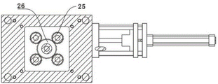
FIG. 6 is a cross-sectional view B-B of FIG. 5 in accordance with the present invention;
fig. 7 is a cross-sectional view of fig. 5 taken along line C-C of the present invention.
Wherein: 1. a lower die base plate; 2. a first cushion block; 3. a first mounting plate; 4. a second mounting plate; 5. a third mounting plate; 6. a lower template; 7. a first guide bar; 8. a first cylinder; 9. a fourth mounting plate; 10. a sliding plate; 11. a second guide bar; 12. mounting a template; 13. a base plate; 14. an upper die base plate; 15. a gate; 16. a buffer rod; 17. forming and demoulding; 18. a shunt channel; 19. a material injection pipe; 20. a spring; 21. an air inlet; 22. a rack; 23. a first gear; 24. a mounting seat; 25. a second gear; 26. a third gear; 27. and an air outlet.
Detailed Description
The present invention will be described in detail with reference to fig. 1 to 7, and the technical solutions in the embodiments of the present invention will be clearly and completely described below, and it is obvious that the described embodiments are only a part of the embodiments of the present invention, and not all embodiments. All other embodiments, which can be derived by a person skilled in the art from the embodiments given herein without making any creative effort, shall fall within the protection scope of the present invention.
The invention provides an injection mould convenient for demoulding of internal threads by improvement, which comprises a lower mould bottom plate 1, wherein a pair of first cushion blocks 2 are fixedly arranged on two sides of the upper end surface of the lower mould bottom plate 1; the invention also comprises a first mounting plate 3 fixedly arranged on the upper end surfaces of the two first cushion blocks 2, a fourth mounting plate 9 arranged on the side surface of the first mounting plate 3, a first cylinder 8 arranged on the end surface of the fourth mounting plate 9 far away from the first mounting plate 3, a mounting seat 24 arranged between the two cushion blocks 2 and fixedly arranged on the upper end surface of the lower die bottom plate 1, a second mounting plate 4 fixedly arranged on the upper end surface of the first mounting plate 3, a third mounting plate 5 fixedly arranged on the upper end surface of the second mounting plate 4, a plurality of forming stripping modules 17 rotatably connected on the upper end surface of the fourth mounting plate 9, the first cylinder 8 driving the forming stripping modules 17 to rotate, threads processed on the tops of the forming stripping modules 17, and a round table shape below the thread sections of the forming stripping modules 17, the lower die plate 6 is connected above the third mounting plate 5 in a sliding manner, the forming demoulding block 17 is matched with a forming cavity of the lower die plate 6, the invention further comprises an upper die plate 12 connected above the lower die plate 6 in a sliding manner, the invention further comprises a first backing plate 13 fixedly arranged on the upper end surface of the upper die plate 13, a first mounting cavity is arranged in the first backing plate 13, the invention further comprises a runner 18 arranged in the first mounting cavity and communicated with the forming cavity of the upper die plate 12, the invention further comprises an upper die base plate 14 fixedly arranged on the upper end surface of the first backing plate 13, the runner 18 is connected with the upper die plate 12, the first backing plate 13 and the upper die base plate 14 in a sliding manner, and the invention further comprises a sprue 15 arranged on the upper end surface of the upper die base plate 14 and communicated with.
When the invention is operated; the injection molding machine pushes the upper mold bottom plate 14 to slide, the upper mold plate 12 and the lower mold plate 6 are folded, the injection molding machine continues to slide downwards until the molding demolding module 17 rises to the maximum stroke, the injection molding machine injects materials into the pouring gate 15, the materials are introduced into the molding cavity for molding, after cooling, the upper mold and the lower mold are separated, and meanwhile, the first air cylinder drives the molding demolding module 17 to rotate, and parts are screwed out. The invention has reasonable design, after the part is formed, the upper die and the lower die are separated, and simultaneously, the cylinder pushes the forming demoulding block to rotate, so that the part is screwed out of the forming cavity, and the part and the die are quickly demoulded.
In the embodiment of the invention, an installation seat 24 is arranged between the two cushion blocks 2 and fixedly installed on the upper end surface of the lower die bottom plate 1, a rack 22 is connected with the first air cylinder 8, the rack 22 is connected with the installation seat 24 in a sliding manner, a first gear 23 is arranged between the two cushion blocks 2 and is rotatably connected with the lower die bottom plate 1, and the rack 22 is matched with the first gear 23.
A second mounting cavity is arranged in the second mounting plate 4, a third gear 26 is arranged in the second mounting cavity, and the third gear 26 is connected with the first gear 23 through a shaft;
the shaping takes off module 17 lower extreme and runs through third mounting panel 5 and second installation cavity and is connected with the rotation of first mounting panel 3, the shaping takes off module 17 and installs second gear 25 in second installation cavity section, second gear 25 and the meshing of third gear 26.
A plurality of second guide rods 11 are arranged between the fourth mounting plate 9 and the first mounting plate 3, the fourth mounting plate 9 and the second guide rods 11 are fixedly connected, a sliding plate 10 is sleeved outside the plurality of second guide rods 11, the sliding plate 10 is slidably connected with the second guide rods 11, the sliding plate 11 is connected with a piston rod of the first air cylinder 8, and the sliding plate 11 is connected with the rack 22.
The rack 16 drives the first gear 23 to rotate, the third gear 26 coaxial with the first gear 23 rotates along with the first gear, the second gear 25 is driven to rotate, and the forming demoulding block 17 rotates along with the second gear.
In the embodiment of the invention, a plurality of first guide rods 7 are fixedly mounted on the upper end surface of the third mounting plate 5, the lower template 6 is connected with the first guide rods 7 in a sliding manner, and the upper template 12 is connected with the first guide rods 7 in a sliding manner.
The movement of the upper template 12 and the lower template 6 is guided, and the movement precision is improved.
In the embodiment of the present invention, a discharge port of the branch channel 18 is provided with a material injection pipe 19, the material injection pipe 19 is slidably connected with the first backing plate 13 and the upper mold plate 12, and a spring 20 is sleeved outside the material injection pipe 19.
Furthermore, a plurality of buffer rods 16 are arranged between the lower die plate 6 and the third mounting plate 5, so that vibration generated during die assembly of the upper die and the lower die is relieved, and the stability of the die is improved.
Further, the cope match-plate pattern side sets up an air inlet 21, air inlet 21 and cope match-plate pattern 12 become the die cavity intercommunication, through the trachea intercommunication between the 12 die cavities of cope match-plate pattern, air inlet 21 one side sets up an air outlet 27, air outlet 27 and cope match-plate pattern 12 become the die cavity intercommunication, and in the part cooling shaping process, to letting in cold air in the shaping intracavity for the shaping speed of part improves cooling efficiency. Reasonable design air inlet and gas outlet, part cooling forming in-process lets in cold air to the shaping intracavity for the shaping speed of part improves cooling efficiency.
The invention has the following improvements and advantages;
the injection mold convenient for internal thread demolding is provided by the improvement 1, and comprises a lower mold bottom plate 1, and a pair of first cushion blocks 2 are fixedly arranged on two sides of the upper end surface of the lower mold bottom plate 1; the invention also comprises a first mounting plate 3 fixedly arranged on the upper end surfaces of the two first cushion blocks 2, a fourth mounting plate 9 arranged on the side surface of the first mounting plate 3, a first cylinder 8 arranged on the end surface of the fourth mounting plate 9 far away from the first mounting plate 3, a mounting seat 24 arranged between the two cushion blocks 2 and fixedly arranged on the upper end surface of the lower die bottom plate 1, a second mounting plate 4 fixedly arranged on the upper end surface of the first mounting plate 3, a third mounting plate 5 fixedly arranged on the upper end surface of the second mounting plate 4, a plurality of forming stripping modules 17 rotatably connected on the upper end surface of the fourth mounting plate 9, the first cylinder 8 driving the forming stripping modules 17 to rotate, threads processed on the tops of the forming stripping modules 17, and a round table shape below the thread sections of the forming stripping modules 17, the lower die plate 6 is connected above the third mounting plate 5 in a sliding manner, the forming demoulding block 17 is matched with a forming cavity of the lower die plate 6, the invention further comprises an upper die plate 12 connected above the lower die plate 6 in a sliding manner, the invention further comprises a first backing plate 13 fixedly arranged on the upper end surface of the upper die plate 13, a first mounting cavity is arranged in the first backing plate 13, the invention further comprises a runner 18 arranged in the first mounting cavity and communicated with the forming cavity of the upper die plate 12, the invention further comprises an upper die base plate 14 fixedly arranged on the upper end surface of the first backing plate 13, the runner 18 is connected with the upper die plate 12, the first backing plate 13 and the upper die base plate 14 in a sliding manner, and the invention further comprises a sprue 15 arranged on the upper end surface of the upper die base plate 14 and communicated with.
2, when the invention is operated; the injection molding machine pushes the upper mold bottom plate 14 to slide, the upper mold plate 12 and the lower mold plate 6 are folded, the injection molding machine continues to slide downwards until the molding demolding module 17 rises to the maximum stroke, the injection molding machine injects materials into the pouring gate 15, the materials are introduced into the molding cavity for molding, after cooling, the upper mold and the lower mold are separated, and meanwhile, the first air cylinder drives the molding demolding module 17 to rotate, and parts are screwed out. The invention has reasonable design, after the part is formed, the upper die and the lower die are separated, and simultaneously, the cylinder pushes the forming demoulding block to rotate, so that the part is screwed out of the forming cavity, and the part and the die are quickly demoulded.
3, in the embodiment of the present invention, an installation seat 24 is disposed between the two cushion blocks 2 and fixedly installed on the upper end surface of the lower mold bottom plate 1, a rack 22 is connected with the first cylinder 8, the rack 22 is slidably connected with the installation seat 24, a first gear 23 is disposed between the two cushion blocks 2 and rotatably connected with the lower mold bottom plate 1, and the rack 22 and the first gear 23 are kept in fit. A second mounting cavity is arranged in the second mounting plate 4, a third gear 26 is arranged in the second mounting cavity, and the third gear 26 is connected with the first gear 23 through a shaft; the shaping takes off module 17 lower extreme and runs through third mounting panel 5 and second installation cavity and is connected with the rotation of first mounting panel 3, the shaping takes off module 17 and installs second gear 25 in second installation cavity section, second gear 25 and the meshing of third gear 26.
And 4, a plurality of second guide rods 11 are arranged between the fourth mounting plate 9 and the first mounting plate 3, the fourth mounting plate 9 and the second guide rods 11 are fixedly connected, a sliding plate 10 is sleeved outside the plurality of second guide rods 11, the sliding plate 10 is slidably connected with the second guide rods 11, the sliding plate 11 is connected with a piston rod of the first air cylinder 8, and the sliding plate 11 is connected with the rack 22. The rack 16 drives the first gear 23 to rotate, the third gear 26 coaxial with the first gear 23 rotates along with the first gear, the second gear 25 is driven to rotate, and the forming demoulding block 17 rotates along with the second gear.
In the embodiment of the invention, a plurality of first guide rods 7 are fixedly mounted on the upper end surface of the third mounting plate 5, the lower template 6 is connected with the first guide rods 7 in a sliding manner, and the upper template 12 is connected with the first guide rods 7 in a sliding manner. The movement of the upper template 12 and the lower template 6 is guided, and the movement precision is improved.
6, in the embodiment of the present invention, a discharge port of the branch channel 18 is provided with a material injection pipe 19, the material injection pipe 19 is slidably connected with the first backing plate 13 and the upper die plate 12, and a spring 20 is sleeved outside the material injection pipe 19.
And 7, furthermore, a plurality of buffer rods 16 are arranged between the lower template 6 and the third mounting plate 5, so that the vibration generated during the die assembly of the upper die and the lower die is reduced, and the stability of the die is improved.
Its 8, the cope match-plate pattern side sets up an air inlet 21, air inlet 21 and cope match-plate pattern 12 become the die cavity intercommunication, through trachea intercommunication between the 12 die cavities of cope match-plate pattern, air inlet 21 one side sets up an air outlet 27, air outlet 27 and cope match-plate pattern 12 become the die cavity intercommunication, and in the part cooling shaping process, let in the cold air to the shaping intracavity for the shaping speed of part improves cooling efficiency. Reasonable design air inlet and gas outlet, part cooling forming in-process lets in cold air to the shaping intracavity for the shaping speed of part improves cooling efficiency.
The previous description of the disclosed embodiments is provided to enable any person skilled in the art to make or use the present invention. Various modifications to these embodiments will be readily apparent to those skilled in the art, and the generic principles defined herein may be applied to other embodiments without departing from the spirit or scope of the invention. Thus, the present invention is not intended to be limited to the embodiments shown herein but is to be accorded the widest scope consistent with the principles and novel features disclosed herein.
Claims (8)
1. The utility model provides an injection mould convenient to internal thread drawing of patterns which characterized in that: the injection mould comprises a lower mould bottom plate (1);
the injection mould also comprises a pair of first cushion blocks (2) which are fixedly arranged on two sides of the upper end surface of the lower mould bottom plate (1);
the injection mould also comprises a first mounting plate (3) which is fixedly mounted on the upper end surfaces of the two first cushion blocks (2);
the injection mould also comprises a fourth mounting plate (9) which is arranged on the side surface of the first mounting plate (3);
the injection mould also comprises a first cylinder (8) which is arranged on the end surface of the fourth mounting plate (9) far away from the first mounting plate (3);
the injection mould also comprises a mounting seat (24) which is arranged between the two cushion blocks (2) and is fixedly arranged on the upper end surface of the lower mould bottom plate (1);
the injection mould also comprises a second mounting plate (4) which is fixedly mounted on the upper end surface of the first mounting plate (3);
the injection mould also comprises a third mounting plate (5) which is fixedly mounted on the upper end surface of the second mounting plate (4);
the injection mould also comprises a plurality of forming demoulding blocks (17) which are rotatably connected with the upper end surface of the fourth mounting plate (9); the first air cylinder (8) drives the forming demoulding block (17) to rotate; the top of the forming demoulding block (17) is provided with a thread; the lower part of the threaded section of the forming demoulding block (17) is in a circular truncated cone shape;
the injection mould also comprises a lower template (6) which is connected above the third mounting plate (5) in a sliding way; the forming demoulding block (17) is matched with a forming cavity of the lower template (6);
the injection mould also comprises an upper template (12) which is connected above the lower template (6) in a sliding way;
the injection mould also comprises a first base plate (13) which is fixedly arranged on the upper end surface of the upper template (13); a first mounting cavity is arranged in the first base plate (13);
the injection mould also comprises a runner (18) which is arranged in the first mounting cavity and communicated with the forming cavity of the upper template (12);
the injection mould also comprises an upper mould bottom plate (14) which is fixedly arranged on the upper end surface of the first base plate (13); the sub-runners (18) are connected with the upper die plate (12), the first base plate (13) and the upper die bottom plate (14) in a sliding mode;
the injection mould also comprises a pouring gate (15) which is arranged on the upper end surface of the upper mould bottom plate (14) and communicated with the runner (18).
2. The injection mold for facilitating demolding of an internal thread as claimed in claim 1, wherein: a mounting seat (24) is arranged between the first cushion blocks (2), the mounting seat is fixedly mounted on the upper end surface of the lower die bottom plate (1), a rack (22) is connected with the first air cylinder (8), the rack (22) is in sliding connection with the mounting seat (24), and a first gear (23) is arranged between the two cushion blocks (2) and rotates with the lower die bottom plate (1)
The rack (22) is connected with a first gear (23) in a maintaining and matching mode;
a second mounting cavity is arranged in the second mounting plate (4), a third gear (26) is arranged in the second mounting cavity, and the third gear (26) is connected with the first gear (23) through a shaft;
the shaping takes off module (17) lower extreme and runs through third mounting panel (5) and second installation cavity and first mounting panel (3) and rotate and be connected, the shaping takes off module (17) and installs second gear (25) in second installation cavity section, second gear (25) and third gear (26) meshing.
3. The injection mold for facilitating demolding of an internal thread as claimed in claim 1, wherein: a plurality of second guide rods (11) are arranged between the fourth mounting plate (9) and the first mounting plate (3), the fourth mounting plate (9) and the second guide rods (11) are fixedly connected, a sliding plate (10) is sleeved outside the second guide rods (11), the sliding plate (10) is slidably connected with the second guide rods (11), the sliding plate (11) is connected with a piston rod of the first air cylinder (8), and the sliding plate (11) is connected with the rack (22) in a maintaining mode.
4. The injection mold for facilitating demolding of an internal thread as claimed in claim 1 or 2, wherein: the upper end face of the third mounting plate (5) is fixedly provided with a plurality of first guide rods (7), the lower template (6) is connected with the first guide rods (7) in a sliding mode, and the upper template (12) is connected with the first guide rods (7) in a sliding mode.
5. The injection mold for facilitating demolding of an internal thread as claimed in claim 1, wherein: and a plurality of buffer rods (16) are arranged between the lower template (6) and the third mounting plate (5).
6. The injection mold for facilitating demolding of an internal thread as claimed in claim 1, wherein: the improved die is characterized in that an air inlet (21) is formed in the side face of the upper die plate (12), the air inlet (21) is communicated with the forming cavity of the upper die plate (12), the upper die plate (12) is communicated with the forming cavity through an air pipe, an air outlet (27) is formed in one side of the air inlet (21), and the air outlet (27) is communicated with the forming cavity of the upper die plate (12).
7. The injection mold for facilitating demolding of an internal thread as claimed in claim 1, wherein: the material injection pipe (19) is arranged at the discharge hole of the sub-flow passage (18), the material injection pipe (19) is connected with the first base plate (13) and the upper template (12) in a sliding mode, and a spring (20) is sleeved outside the material injection pipe (19).
8. A method of operating an injection mold for facilitating stripping of internal threads according to claim 1, wherein: the injection molding machine pushes the upper mold bottom plate (14) to slide, the upper mold plate (12) and the lower mold plate (6) are folded and continue to slide downwards until the molding demolding block (17) rises to the maximum stroke, the injection molding machine injects materials into the pouring gate (15), the materials are introduced into the molding cavity for molding, after cooling, the upper mold and the lower mold are separated, and meanwhile, the first air cylinder drives the molding demolding block (17) to rotate, and the part is screwed out.
Priority Applications (1)
| Application Number | Priority Date | Filing Date | Title |
|---|---|---|---|
| CN202110122103.5A CN112743774A (en) | 2021-01-29 | 2021-01-29 | Injection mold convenient for internal thread demolding and operation method |
Applications Claiming Priority (1)
| Application Number | Priority Date | Filing Date | Title |
|---|---|---|---|
| CN202110122103.5A CN112743774A (en) | 2021-01-29 | 2021-01-29 | Injection mold convenient for internal thread demolding and operation method |
Publications (1)
| Publication Number | Publication Date |
|---|---|
| CN112743774A true CN112743774A (en) | 2021-05-04 |
Family
ID=75653268
Family Applications (1)
| Application Number | Title | Priority Date | Filing Date |
|---|---|---|---|
| CN202110122103.5A Pending CN112743774A (en) | 2021-01-29 | 2021-01-29 | Injection mold convenient for internal thread demolding and operation method |
Country Status (1)
| Country | Link |
|---|---|
| CN (1) | CN112743774A (en) |
Cited By (1)
| Publication number | Priority date | Publication date | Assignee | Title |
|---|---|---|---|---|
| CN117734125A (en) * | 2023-12-20 | 2024-03-22 | 上海凌田精密模塑有限公司 | An automatic demoulding device for injection molds |
-
2021
- 2021-01-29 CN CN202110122103.5A patent/CN112743774A/en active Pending
Cited By (1)
| Publication number | Priority date | Publication date | Assignee | Title |
|---|---|---|---|---|
| CN117734125A (en) * | 2023-12-20 | 2024-03-22 | 上海凌田精密模塑有限公司 | An automatic demoulding device for injection molds |
Similar Documents
| Publication | Publication Date | Title |
|---|---|---|
| CN114872280A (en) | Precision injection mold capable of achieving rapid injection molding | |
| CN208148388U (en) | A kind of internal screw thread rotation depanning mold | |
| CN219381420U (en) | Injection mold | |
| CN221249729U (en) | A thread demoulding die | |
| CN219564026U (en) | Injection molding equipment convenient to drawing of patterns | |
| CN216423290U (en) | Precision mold for plastic-coated molding and overlapping injection molding | |
| CN216804241U (en) | Prevent that finished product warp takes off model injection mold fast | |
| CN215703316U (en) | Mould with front mould inclined slide block separating mechanism | |
| CN214982891U (en) | Automobile injection mold for back-off demolding | |
| CN213166614U (en) | Safe and rapid demoulding injection mold | |
| CN111823509B (en) | A processing mold for synchronously withdrawing, spinning off and ejecting products on the glue inlet side | |
| CN117245865A (en) | An ejection structure dedicated to small undercuts on products | |
| CN213002508U (en) | Roller processing blank forming die | |
| CN210758924U (en) | Rotary demolding mold | |
| CN223735368U (en) | Double-colored mould with oblique guide pillar and slider mechanism | |
| CN216941663U (en) | Rotary core-pulling device of combined sliding block | |
| CN222290871U (en) | Injection mold easy to demolding | |
| CN223573673U (en) | A plastic mold with a demolding mechanism | |
| CN223775978U (en) | A die casting mold | |
| CN206780886U (en) | Front Roller Brush Forming Mold | |
| CN223394286U (en) | Via hole forming die-casting structure | |
| CN219968683U (en) | Injection mold screw thread demoulding mechanism | |
| CN219789153U (en) | Precision injection molding inclined top demoulding device | |
| CN223790927U (en) | Deep cavity injection mold for plastic storage boxes | |
| CN218985604U (en) | Injection mold |
Legal Events
| Date | Code | Title | Description |
|---|---|---|---|
| PB01 | Publication | ||
| PB01 | Publication | ||
| SE01 | Entry into force of request for substantive examination | ||
| SE01 | Entry into force of request for substantive examination |