CN112743009A - Automatic cutting equipment for steel wire products - Google Patents
Automatic cutting equipment for steel wire products Download PDFInfo
- Publication number
- CN112743009A CN112743009A CN202110088909.7A CN202110088909A CN112743009A CN 112743009 A CN112743009 A CN 112743009A CN 202110088909 A CN202110088909 A CN 202110088909A CN 112743009 A CN112743009 A CN 112743009A
- Authority
- CN
- China
- Prior art keywords
- steel wire
- plate
- cutting
- clamping
- clutch
- Prior art date
- Legal status (The legal status is an assumption and is not a legal conclusion. Google has not performed a legal analysis and makes no representation as to the accuracy of the status listed.)
- Granted
Links
- 229910000831 Steel Inorganic materials 0.000 title claims abstract description 150
- 239000010959 steel Substances 0.000 title claims abstract description 150
- 238000005520 cutting process Methods 0.000 title claims abstract description 110
- 239000000463 material Substances 0.000 claims abstract description 14
- 230000005540 biological transmission Effects 0.000 claims description 27
- 238000003825 pressing Methods 0.000 claims description 15
- 238000009434 installation Methods 0.000 claims description 4
- 230000003993 interaction Effects 0.000 claims description 4
- 230000009471 action Effects 0.000 claims description 3
- 238000004804 winding Methods 0.000 claims description 3
- 238000000034 method Methods 0.000 abstract description 8
- 230000000694 effects Effects 0.000 abstract description 7
- 230000008569 process Effects 0.000 abstract description 4
- 238000012545 processing Methods 0.000 description 8
- 238000000926 separation method Methods 0.000 description 7
- 230000004048 modification Effects 0.000 description 6
- 238000012986 modification Methods 0.000 description 6
- 238000004519 manufacturing process Methods 0.000 description 4
- 239000012634 fragment Substances 0.000 description 3
- 238000010008 shearing Methods 0.000 description 3
- 238000010923 batch production Methods 0.000 description 2
- 230000008859 change Effects 0.000 description 2
- 230000007246 mechanism Effects 0.000 description 2
- 230000009286 beneficial effect Effects 0.000 description 1
- 230000008901 benefit Effects 0.000 description 1
- 238000007664 blowing Methods 0.000 description 1
- 230000003749 cleanliness Effects 0.000 description 1
- 230000008878 coupling Effects 0.000 description 1
- 238000010168 coupling process Methods 0.000 description 1
- 238000005859 coupling reaction Methods 0.000 description 1
- 238000013461 design Methods 0.000 description 1
- 238000007599 discharging Methods 0.000 description 1
- 230000006872 improvement Effects 0.000 description 1
- 238000003780 insertion Methods 0.000 description 1
- 230000037431 insertion Effects 0.000 description 1
- 238000003754 machining Methods 0.000 description 1
- 238000004080 punching Methods 0.000 description 1
- 238000012958 reprocessing Methods 0.000 description 1
- 238000006467 substitution reaction Methods 0.000 description 1
- 230000007306 turnover Effects 0.000 description 1
- 239000002699 waste material Substances 0.000 description 1
Images




Classifications
-
- B—PERFORMING OPERATIONS; TRANSPORTING
- B21—MECHANICAL METAL-WORKING WITHOUT ESSENTIALLY REMOVING MATERIAL; PUNCHING METAL
- B21F—WORKING OR PROCESSING OF METAL WIRE
- B21F1/00—Bending wire other than coiling; Straightening wire
- B21F1/02—Straightening
- B21F1/026—Straightening and cutting
-
- B—PERFORMING OPERATIONS; TRANSPORTING
- B21—MECHANICAL METAL-WORKING WITHOUT ESSENTIALLY REMOVING MATERIAL; PUNCHING METAL
- B21F—WORKING OR PROCESSING OF METAL WIRE
- B21F11/00—Cutting wire
-
- B—PERFORMING OPERATIONS; TRANSPORTING
- B21—MECHANICAL METAL-WORKING WITHOUT ESSENTIALLY REMOVING MATERIAL; PUNCHING METAL
- B21F—WORKING OR PROCESSING OF METAL WIRE
- B21F23/00—Feeding wire in wire-working machines or apparatus
-
- Y—GENERAL TAGGING OF NEW TECHNOLOGICAL DEVELOPMENTS; GENERAL TAGGING OF CROSS-SECTIONAL TECHNOLOGIES SPANNING OVER SEVERAL SECTIONS OF THE IPC; TECHNICAL SUBJECTS COVERED BY FORMER USPC CROSS-REFERENCE ART COLLECTIONS [XRACs] AND DIGESTS
- Y02—TECHNOLOGIES OR APPLICATIONS FOR MITIGATION OR ADAPTATION AGAINST CLIMATE CHANGE
- Y02P—CLIMATE CHANGE MITIGATION TECHNOLOGIES IN THE PRODUCTION OR PROCESSING OF GOODS
- Y02P70/00—Climate change mitigation technologies in the production process for final industrial or consumer products
- Y02P70/10—Greenhouse gas [GHG] capture, material saving, heat recovery or other energy efficient measures, e.g. motor control, characterised by manufacturing processes, e.g. for rolling metal or metal working
Landscapes
- Engineering & Computer Science (AREA)
- Mechanical Engineering (AREA)
- Wire Processing (AREA)
Abstract
The invention discloses automatic cutting equipment for steel wire products, which comprises a rack platform, wherein a straightening component, a feeding component, a clamping component and a cutting component are sequentially arranged on the rack platform from right to left; through aligning subassembly, pay-off subassembly, clamping components, cutting assembly, each module moves in coordination, has realized that the product is automatic to be straightened, wire rod pay-off, the location is pressed from both sides tight, a whole set of automatic operation processes such as the automatic blanking of product cutting, can adapt to the cutting of different length, diameter product, and section high quality, stable high efficiency are compared CNC equipment process time weak point, save artifical clamping, get the material operation, in aspects such as productivity, yield, and personnel's operational environment, all have apparent effect to promote.
Description
Technical Field
The invention relates to the technical field of steel wire cutting equipment, in particular to automatic cutting equipment for steel wire products.
Background
When small steel wire products are cut off, the small steel wire products are cut into small sections after being straightened, and are clamped, cut and taken by a CNC (computer numerical control) machine; the circulation and turnover time are long, the fatigue degree of manual operation is high, and the product is damaged due to the easy error of material taking and discharging. Finally, the waste of equipment resources and the increase of manufacturing cost are caused. In the other method, coiled steel wire materials are directly used for punching and blanking after being straightened on line, but burrs which cannot be ground are generated, so that the appearance is unqualified.
The invention discloses a cutting die for thin round steel and steel wires with various specifications, publication No. CN 108296395A, publication No. 2018.07.20, and relates to the technical field of design and manufacture of machining and stamping professional dies. The invention solves the problems of high processing difficulty, low production efficiency and difficulty in meeting the requirement of batch production of the conventional thin round steel and steel wire materials. The lower die is arranged in the middle of the upper end surface of the lower die base, the upper part of the lower die is provided with a plurality of shearing holes, two guide posts are arranged at the position, close to the back, of the lower die base, the upper die is arranged in the middle of the lower end surface of the upper die base, the lower part of the upper die is provided with a plurality of shearing openings, two guide sleeves are arranged at the position, close to the back, of the upper die base, the two guide sleeves are fixedly connected with the upper die base in an interference fit mode, a die handle is arranged at the middle of the upper end of the upper die base, and the die. The invention is used for shearing all specification thin round steel and steel wires with the diameter not more than 16 mm. Above-mentioned technical scheme solves, and current thin round steel and steel wire material exist the processing degree of difficulty big, and production efficiency is low, and is difficult to satisfy the problem of batch production needs, but does not relate to full automated control steel wire product automatic cutout, realizes the aligning of steel wire to and realize the problem of separation and reunion transmission through feeding assembly.
The invention provides efficient and reliable steel wire cutting equipment, which is published under the number CN 109622819A, published under the number 2019.04.16 and comprises a rack and a cutting mechanism, wherein the cutting mechanism is arranged on the rack and comprises a cutting lower base, a cutting upper support, a sliding plate, a cutting upper blade, a cutting lower blade and a cutting cylinder, the cutting lower base is fixedly arranged on the rack, the cutting upper support and the sliding plate are sequentially arranged above the cutting lower base from bottom to top, the cutting lower base, the cutting upper support and the sliding plate are connected through a guide rod, the cutting cylinder is fixedly arranged on the upper surface of the sliding plate, a piston rod of the cutting cylinder penetrates through the sliding plate and is connected with the upper surface of the cutting upper support, the cutting upper blade is fixedly arranged on the cutting upper support, and the cutting lower blade is fixedly arranged in the cutting lower base. The invention has the advantages of improving the working efficiency, having high automation degree, avoiding the phenomenon of wire running and improving the poor cutting precision. Above-mentioned technical scheme solves current cutting device degree of automation low, leads to work efficiency not high, and the reprocessing in-process takes place the problem of running easily, but does not relate to the straightening of steel wire to and realize the separation and reunion transmission through the pay-off subassembly.
Disclosure of Invention
The invention aims to solve the problems and adopts the technical scheme that:
the utility model provides a steel wire product automatic cutout equipment, includes frame platform, frame platform is last to install aligning subassembly, pay-off subassembly, clamping component, cutting assembly in proper order from right to left, is close to aligning subassembly one end on the frame platform and installs the silk dish of winding steel wire, and the steel wire on the silk dish loops through aligning subassembly, pay-off subassembly, clamping component, carries out automatic cutout via cutting assembly.
Further, the straightening assembly comprises a horizontal plate and a vertical plate, the horizontal plate is horizontally arranged, the vertical plate is connected to one end of the horizontal plate and is vertically arranged, the upper end of the horizontal plate protrudes upwards, two rows of stand columns are arranged along the material conveying direction, and a first straightening channel is formed between the two rows of stand columns on the horizontal plate; the front side surface of the vertical plate protrudes outwards, two rows of stand columns are arranged along the material conveying direction, and a second straightening channel is formed between the two rows of stand columns on the vertical plate; the first straightening channel and the second straightening channel are positioned on the same straight line.
Furthermore, the transverse plate is installed on the rack platform in a matched mode through the installation seat.
Furthermore, the feeding assembly comprises two feeding groups which are arranged on the base along the feeding direction, each feeding group comprises a pair of mounting plates which are vertically arranged oppositely, a fixed rubber wheel is arranged between the corresponding mounting plates, two ends of the fixed rubber wheel are respectively matched with the corresponding mounting plates in a rotating and inserting manner, one end of the fixed rubber wheel extends out of the corresponding mounting plate and is sequentially provided with a transmission gear and a belt wheel along the axial direction, and the belt wheels on the two feeding groups are connected through a belt;
the lower end of the transmission gear is connected with a driving gear in a matching way, and the driving gear is connected with a power set; the clutch component is positioned above the fixed rubber wheel and is slidably mounted on the mounting plate, the clutch component is matched with the fixed rubber wheel in a clutch action mode and comprises sliding blocks which are respectively slidably mounted on a pair of mounting plates, a sliding frame is arranged on each mounting plate, each sliding block is positioned in each sliding frame and slides along the vertical direction, the clutch rubber wheel is mounted between every two corresponding sliding blocks, two ends of each clutch rubber wheel are respectively matched with the corresponding sliding blocks in a rotating and inserting mode, a driven gear matched with the transmission gear is mounted outside the corresponding sliding block at one end of each clutch rubber wheel, a bolt is mounted at the upper end of each mounting plate in an inserting mode, the bolt is mounted in each sliding frame and arranged at intervals with the corresponding sliding block, a spring is sleeved on each bolt, the upper end of each spring abuts against the; the sliding block is rotatably inserted with a clutch rod, two ends of the clutch rod penetrate through the sliding block and are externally connected with an oval clutch block, one end of the clutch rod is positioned outside the oval clutch block and is also connected with a clutch handle, and the mounting plate is provided with a clutch support block which is in butt fit with the oval clutch block.
Furthermore, a limiting hole is formed in the sliding block, the bolt is inserted into the limiting hole, and the lower end portion of the spring is located in the limiting hole.
Further, the clamping assembly comprises a clamping base, a steel wire lower clamping plate is mounted on the clamping base, a steel wire upper clamping plate is mounted above the steel wire lower clamping plate and close to one end of the feeding assembly in a buckling mode, and a steel wire hole is formed in the clamping matching position of the steel wire lower clamping plate and the steel wire upper clamping plate;
a movable clamping pressing block is buckled and mounted at one end, close to the cutting assembly, above the steel wire lower clamping plate, and a clamping hole is formed at the clamping matching position of the steel wire lower clamping plate and the movable clamping pressing block; the movable clamping pressing block is connected with a clamping cylinder installed on the clamping base, and a cutting groove for the cutting assembly to work is formed in the movable clamping pressing block.
Further, the steel wire lower plate is located cutting assembly one end and installs the blanking mouthpiece, install the collets between steel wire lower plate and the blanking mouthpiece, the collets up end protrusion is equipped with the conducting block, the up end of collets is not higher than the up end of steel wire lower plate, and the conducting block is higher than the up end setting of steel wire lower plate.
Further, the cutting assembly comprises a cutting bottom plate, two guide shafts are vertically arranged on the cutting bottom plate, a fixing plate which slides along the axial direction of the guide shafts is arranged above the cutting bottom plate, and a pushing cylinder is arranged between the cutting bottom plate and the fixing plate;
the fixed plate is detachably provided with an adjusting block, the upper end face of the adjusting block is provided with a spindle seat, one end of the spindle seat is connected with a servo motor through a coupler, and the other end of the spindle seat is connected with a saw blade through a locking pressing block.
Furthermore, a human-computer interaction panel is further installed on the rack platform.
Furthermore, splash-proof fences are arranged around the rack platform.
The invention has the following beneficial effects:
1. the invention relates to automatic cutting equipment for steel wire products, which realizes a whole set of automatic operation procedures of automatic product straightening, wire feeding, positioning and clamping, automatic product cutting and blanking and the like through the cooperative operation of a straightening assembly, a feeding assembly, a clamping assembly and a cutting assembly and can adapt to the cutting of products with different lengths and diameters, the section quality is high, the stability and the efficiency are high, the processing time is short compared with CNC equipment, the manual clamping and the material taking operation are omitted, and the remarkable effects are improved in the aspects of productivity, yield, personnel operation environment and the like.
2. According to the invention, the straightening component is adopted, and the first straightening channel and the second straightening channel are set to limit the steel wire product in four circumferential directions, so that the steel wire product can only move along the conveying direction, and the straightening of the steel wire product is realized.
3. According to the steel wire straightening and clamping device, the feeding assembly is adopted to convey steel wires on the wire disc, the steel wire products are straightened and clamped through transmission of the feeding assembly, and finally the steel wire products are cut by the cutting assembly.
4. The clutch component is adopted in the invention, the separation of the fixed rubber wheel and the clutch component is firstly realized, the steel wire is sent between the fixed rubber wheel and the clutch component, then the combination of the fixed rubber wheel and the clutch component is realized, and the steel wire between the fixed rubber wheel and the clutch component is clamped for convenient conveying.
5. According to the invention, the clamping assembly is adopted to clamp and position the steel wire conveyed by the feeding assembly, so that the cutting assembly can conveniently perform cutting processing.
Drawings
FIG. 1 is a schematic structural view of the present invention;
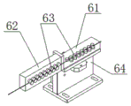
FIG. 2 is a schematic view of the structure of a straightening assembly according to the present invention;
FIG. 3 is a schematic three-dimensional structure of a feeding assembly according to the present invention;
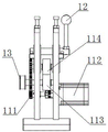
FIG. 4 is a right side view of the feed assembly of the present invention;
FIG. 5 is a schematic three-dimensional view of a clamping assembly according to the present invention;
FIG. 6 is a front view of the clamping assembly of the present invention;
FIG. 7 is a left side view of the clamping assembly of the present invention;
FIG. 8 is a cross-sectional view of the clamping assembly of the present invention taken along C-C of FIG. 7;
FIG. 9 is a schematic three-dimensional view of a cutting assembly according to the present invention;
fig. 10 is a front view of the cutting assembly of the present invention.
Detailed Description
The present embodiment is not intended to limit the shape, material, structure, etc. of the present invention in any way, and any simple modification, equivalent change and modification made to the above embodiments according to the technical spirit of the present invention are within the scope of the technical solution of the present invention.
In the description of the present invention, it is to be understood that the terms "central", "longitudinal", "lateral", "front", "rear", "left", "right", "vertical", "horizontal", "top", "bottom", "inner", "outer", etc., indicate orientations or positional relationships based on those shown in the drawings, and are used only for convenience in describing the present invention and for simplicity in description, and do not indicate or imply that the referenced devices or elements must have a particular orientation, be constructed and operated in a particular orientation, and thus, are not to be considered as limiting the scope of the present invention.
If the terms "first," "second," etc. are used herein to define parts, those skilled in the art will recognize that: the use of "first" and "second" is merely for convenience in describing the invention and to simplify the description, and unless otherwise stated the above words are not intended to have a special meaning.
The invention is further described below with reference to the accompanying drawings.
As shown in figures 1-10, an automatic cutting device for steel wire products is suitable for steel wire products with the diameter of 0.1 mm-1 mm and the length of 3 mm-10 mm, and the specification of the steel wire products is 0.5mm in diameter and 4.86mm in length; including frame platform 7, frame platform 7 is last to install aligning subassembly 6, pay-off subassembly 1, clamping component 2, cutting component 3 from right to left in proper order, and the wire reel 5 of winding steel wire is installed near aligning subassembly 6 one end on frame platform 7, and the steel wire on the wire reel 5 loops through aligning subassembly 6, pay-off subassembly 1, clamping component 2, carries out automatic cutout via cutting component 3, through the transmission of pay-off subassembly 1 for the steel wire product is straightened, presss from both sides tightly, has realized cutting process diameter 0.5mm, long 4.86 mm's steel wire product by cutting component 3 at last.
As shown in fig. 1 to 10, in order to achieve the straightening of the steel wire product, in this embodiment, the straightening assembly 6 includes a horizontal plate 61 placed horizontally and a vertical plate 62 connected to one end of the horizontal plate 61 and placed vertically, the upper end of the horizontal plate 61 protrudes upward and is provided with two rows of upright posts 63 along the feeding direction, and a first straightening channel is formed between the two rows of upright posts 63 on the horizontal plate 61; the front side surface of the vertical plate 62 protrudes outwards, two rows of upright posts 63 are arranged along the material conveying direction, and a second straightening channel is formed between the two rows of upright posts 63 on the vertical plate 62; the first straightening channel and the second straightening channel are located on the same straight line, and the first straightening channel and the second straightening channel limit the circumferential direction of the steel wire product in four directions, so that the steel wire product can only move along the conveying direction, and finally, the straightening of the steel wire product is realized.
In the embodiment shown in fig. 1-10, the cross plate 61 is fitted to the frame platform 7 via a mounting base 64 in order to mount the straightening assembly 6 to the frame platform 7.
As shown in fig. 1-10, in order to realize conveying of steel wires on a wire disc 5, the steel wire product is straightened and clamped by transmission of a feeding assembly 1, and finally cut by a cutting assembly 3, in this embodiment, the feeding assembly 1 includes two groups of feeding sets mounted on a base 11 along a feeding direction, the feeding sets include a pair of mounting plates 12 arranged vertically and oppositely, a fixed rubber wheel 113 is mounted between the pair of mounting plates 12, two ends of the fixed rubber wheel 113 are respectively in rotating and inserting fit with the pair of mounting plates 12, one end of the fixed rubber wheel 113 extends out of the mounting plates 12 and is sequentially provided with a transmission gear 115 and a belt wheel 13 along an axial direction, the fixed rubber wheel 113, the transmission gear 115 and the belt wheel 13 are arranged as a whole, and the belt wheels 13 on the two groups of feeding sets are connected by; the lower end of the transmission gear 115 is connected with a driving gear 111 in a matching manner, the driving gear 111 is connected with a power set, and the power set is a stepping motor 112; a clutch component which is matched with the fixed rubber wheel 113 in a clutch action manner is slidably arranged above the fixed rubber wheel 113 on the mounting plate 12; when the steel wire conveying device works, the stepping motor 112 works, the output end of the stepping motor 112 drives the driving gear 111 to rotate, the driving gear 111 drives the transmission gear 115 to rotate, the transmission gear 115 on the two feeding groups is indirectly driven to rotate through belt transmission, the transmission gear 115 drives the fixed rubber wheel 113 to rotate, and the fixed rubber wheel 113 is matched with the clutch component to clamp so as to realize the transmission of steel wire products.
As shown in fig. 1 to 10, in this embodiment, in order to first separate the fixed rubber wheel 113 from the clutch component, send the steel wire between the fixed rubber wheel 113 and the clutch component, and then combine the fixed rubber wheel 113 with the clutch component, and clamp the steel wire between the fixed rubber wheel 113 and the clutch component for convenient transportation, in this embodiment, the clutch component includes sliding blocks 17 respectively slidably mounted on a pair of mounting plates 12, a sliding frame is disposed on the mounting plate 12, the sliding blocks 17 are located in the sliding frame and slide along the vertical direction, preferably, in this embodiment, a sliding groove is disposed at a matching position of the sliding blocks 17 and the sliding frame; a clutch rubber wheel 114 is arranged between the opposite sliding blocks 17, two ends of the clutch rubber wheel 114 are respectively in rotating insertion fit with the opposite sliding blocks 17, one end of the clutch rubber wheel 114 extends out of the sliding block 17 and is provided with a driven gear 14 matched with a transmission gear 115, a bolt 19 is inserted in the upper end of the mounting plate 12 in a threaded fit manner, the bolt 19 is inserted in the sliding frame and is arranged at intervals with the sliding blocks 17, a spring 18 is sleeved on the bolt 19, the upper end of the spring 18 is abutted to the inner wall of the sliding frame, and the lower end of the spring 18 is abutted to the sliding blocks 17; the spring 18 is always in a state of jacking the sliding block 17; in order to realize the clutch function, in this embodiment, a clutch lever is rotatably inserted into the slider 17, both ends of the clutch lever penetrate through the slider 17 and are connected with an elliptical clutch block 16, one end of the clutch lever is positioned outside the elliptical clutch block 16 and is also connected with a clutch handle 10, and a clutch support block 15 which is in butt fit with the elliptical clutch block 16 is installed on the mounting plate 12. The oval clutch piece 16 may be configured in an oval or semi-circular shape.
As shown in fig. 1-10, when a steel wire needs to be fed between the fixed rubber wheel 113 and the clutch component, to separate the fixed rubber wheel 113 from the clutch component, the clutch lever is rotated relative to the slider 17 by operating the clutch handle 10, the elliptical clutch block 16 on the clutch lever is rotated, so that the long diameter end of the elliptical clutch block 16 is in contact fit with the clutch support block 15, the slider 17 is vertically and upwardly slid in the sliding frame, and the slider 17 compresses the spring 18, so that the clutch rubber wheel 114 is separated from the fixed rubber wheel 113, and the steel wire is inserted into a gap formed by the separation of the clutch rubber wheel 114 and the fixed rubber wheel 113; when the combination of the fixed rubber wheel 113 and the clutch component is to be realized, and the steel wire is clamped by the fixed rubber wheel 113 and the clutch component, the clutch rod is rotated relative to the sliding block 17 by operating the clutch handle 10, the elliptical clutch block 16 on the clutch rod is rotated, so that the short diameter end of the elliptical clutch block 16 is in contact fit with the clutch support block 15, the compressed spring 18 releases energy to extrude the sliding block 17, and the sliding block 17 slides downwards along the vertical direction in the sliding frame, so that the clutch rubber wheel 114 is combined with the fixed rubber wheel 113, the steel wire is clamped by the fixed rubber wheel 113 and the clutch rubber wheel 114, and the steel wire is conveyed by the relative rotation of the fixed rubber wheel 113 and the clutch rubber wheel 114.
As shown in fig. 1 to 10, in order to limit the spring 18, in this embodiment, a limiting hole is formed on the sliding block 17, the bolt 19 is inserted into the limiting hole, and the lower end of the spring 18 is located in the limiting hole.
As shown in fig. 1-10, in order to clamp and position the steel wire conveyed by the feeding assembly 1 and facilitate the cutting of the cutting assembly 3, in this embodiment, the clamping assembly 2 includes a clamping base 21, a steel wire lower clamp plate 27 is mounted on the clamping base 21, an upper steel wire clamp plate 28 is mounted above the lower steel wire clamp plate 27 and close to one end of the feeding assembly 1 in a buckling manner, and a steel wire hole 29 is formed at a clamping fit position of the lower steel wire clamp plate 27 and the upper steel wire clamp plate 28; a movable clamping pressing block 26 is buckled and mounted at one end, close to the cutting assembly 3, above the steel wire lower clamping plate 27, and a clamping hole is formed at the clamping matching position of the steel wire lower clamping plate 27 and the movable clamping pressing block 26; the movable clamping pressing block 26 is connected with a clamping cylinder 22 installed on the clamping base 21, a cutting groove 261 for the cutting assembly 3 to work is formed in the movable clamping pressing block 26, and during cutting work, the saw blade 36 extends into the cutting groove 261 to cut a steel wire. The steel wire that the pay-off subassembly 1 was carried is inserted in steel wire hole 29 and is carried to the clamp hole in succession, and the activity is pressed from both sides tight briquetting 26 and is separated with steel wire lower plate 27 this moment, and after the steel wire was carried to target in place, control die clamping cylinder 22, die clamping cylinder 22 drives the motion of activity and presss from both sides tight briquetting 26 and realize combining with steel wire lower plate 27 for press from both sides the tight hole closure and realize the tight location of clamp of steel wire.
As shown in fig. 1-10, in order to remove the steel scrap fragments generated during cutting and processing and avoid affecting the cutting precision, in this embodiment, the steel wire lower clamp plate 27 is located at one end of the cutting assembly 3 and is provided with the blanking blow nozzle 23, an insulating block 24 is installed between the steel wire lower clamp plate 27 and the blanking blow nozzle 23, an upper end surface of the insulating block 24 is convexly provided with a conductive block 25, an upper end surface of the insulating block 24 is not higher than an upper end surface of the steel wire lower clamp plate 27, and the conductive block 25 is higher than the upper end surface of the steel wire lower clamp plate 27. Through setting the conductive block 25, when the steel wire touches the conductive block 25, a signal is transmitted to the control system, so that the feeding component 1 stops feeding and starts to cut in the next step.
As shown in fig. 1 to 10, in order to cut a steel wire, in this embodiment, the cutting assembly 3 includes a cutting base plate 31, two guide shafts 38 are vertically installed on the cutting base plate 31, a fixing plate 32 that slides along the axial direction of the guide shafts 38 is installed above the cutting base plate 31, and a pushing cylinder 39 is installed between the cutting base plate 31 and the fixing plate 32; the fixed plate 32 is driven to vertically move along the axial direction of the guide shaft 38 through the pushing cylinder 39, so that the cutting assembly 3 cuts the steel wire; the adjusting block 33 is detachably mounted on the fixing plate 32, in the embodiment, the mounting position of the adjusting block 33 along the feeding direction can be set according to requirements, so that the cutting assembly 3 is convenient to be matched with a steel wire; a spindle seat 35 is installed on the upper end surface of the adjusting block 33, one end of the spindle seat 35 is connected with a servo motor 34 through a coupling, and the other end of the spindle seat 35 is connected with a saw blade 36 through a locking pressing block 37. During operation, the servo motor 34 drives the saw blade 36 to rotate, and then the pushing cylinder 39 drives the fixing plate 32 to move downwards along the axial direction of the guide shaft 38, so that the cutting assembly 3 cuts the steel wire.
As shown in fig. 1-10, in order to realize that the worker performs operation control on the automatic steel wire product cutting equipment, a human-computer interaction panel 4 is further installed on the rack platform 7, and the worker controls the working state of the automatic steel wire product cutting equipment through the human-computer interaction panel 4.
As shown in fig. 1 to 10, in order to prevent the steel scrap fragments generated in the process of cutting steel wire products from splashing everywhere, which affects the cleanliness and the working environment of the equipment, in this embodiment, splash-proof fences 8 are installed around the rack platform 7, and the steel scrap fragments are cut onto the rack platform 7 through the splash-proof fences 8, which avoids affecting the working environment.
The working process of the invention is as follows:
when the steel wire straightening machine works, the fixed rubber wheel 113 and the clutch rubber wheel 114 are required to clamp a steel wire so as to be convenient for conveying, the steel wire on the wire disc 5 passes through the first straightening channel and the second straightening channel, and the first straightening channel and the second straightening channel limit the steel wire product in four circumferential directions, so that the steel wire product can only move along the conveying direction, and finally the steel wire product is straightened;
the clutch lever is controlled to rotate relative to the sliding block 17 by controlling the clutch handle 10, the oval clutch block 16 on the clutch lever rotates, the long diameter end of the oval clutch block 16 is in contact fit with the clutch support block 15, the sliding block 17 slides upwards in the sliding frame along the vertical direction, meanwhile, the sliding block 17 compresses the spring 18, thereby separating the clutch rubber wheel 114 from the fixed rubber wheel 113, inserting the steel wire passing through the straightening component 6 into a gap formed by the separation of the clutch rubber wheel 114 and the fixed rubber wheel 113, then the clutch lever is controlled to rotate relative to the sliding block 17 by controlling the clutch handle 10 again, the oval clutch block 16 on the clutch lever rotates, the short-diameter end of the oval clutch block 16 is in contact fit with the clutch support block 15, the compressed spring 18 releases energy to extrude the sliding block 17, the sliding block 17 slides downwards along the vertical direction in the sliding frame, thereby combining the clutch rubber wheel 114 and the fixed rubber wheel 113 and finishing the clamping of the fixed rubber wheel 113 and the clutch rubber wheel 114 to the steel wire.
The stepping motor 112 works, the output end of the stepping motor 112 drives the driving gear 111 to rotate, the driving gear 111 drives the transmission gear 115 to rotate, the transmission gear 115 on the two feeding groups is indirectly driven to rotate through belt transmission, the transmission gear 115 drives the driven gear 14 to rotate, the transmission gear 115 drives the fixed rubber wheel 113 to rotate, the driven gear 14 drives the clutch rubber wheel 114 to rotate, and the steel wire is conveyed through the relative rotation of the fixed rubber wheel 113 and the clutch rubber wheel 114.
The steel wire that the pay-off subassembly 1 was carried is inserted in steel wire hole 29 and is carried to the clamp hole in continuing, and the tight briquetting of activity clamp 26 and the separation of steel wire lower plate 27 this moment, when the steel wire touched conducting block 25, transmission signal to control system realized that pay-off subassembly 1 stops the defeated material, controlled die clamping cylinder 22 simultaneously, die clamping cylinder 22 drives the tight briquetting of activity clamp 26 motion realization and combines with steel wire lower plate 27 for the tight hole closure of clamp realizes the tight location of clamp of steel wire.
The servo motor 34 drives the saw blade 36 to rotate, and then the fixed plate 32 is driven to move downwards along the axial direction of the guide shaft 38 through the pushing cylinder 39, so that the cutting assembly 3 cuts the steel wire; after cutting, the scrap steel generated during cutting processing is removed through the blanking blowing nozzle 23, and the cutting precision is prevented from being influenced.
The invention relates to automatic cutting equipment for steel wire products, which realizes a whole set of automatic operation procedures of automatic product straightening, wire feeding, positioning and clamping, automatic product cutting and blanking and the like by the cooperative operation of a straightening component 6, a feeding component 1, a clamping component 2 and a cutting component 3 through the modules, can adapt to the cutting of products with different lengths and diameters, has high section quality, stability and high efficiency, has short processing time compared with CNC equipment, saves manual clamping and material taking operation, and has remarkable effect improvement on the aspects of capacity, yield, personnel operation environment and the like.
According to the invention, the straightening component 6 is adopted, and the steel wire product is limited in four circumferential directions through the set first straightening channel and the set second straightening channel, so that the steel wire product can only move along the conveying direction, and the straightening of the steel wire product is realized.
According to the invention, the feeding component 1 is adopted to convey the steel wires on the wire disc 5, the steel wire products are straightened and clamped through the transmission of the feeding component 1, and finally the steel wire products are cut by the cutting component 3.
In the invention, the clutch component is adopted, the separation of the fixed rubber wheel 113 and the clutch component is firstly realized, the steel wire is sent between the fixed rubber wheel 113 and the clutch component, then the combination of the fixed rubber wheel 113 and the clutch component is realized, and the steel wire between the fixed rubber wheel 113 and the clutch component is clamped for convenient conveying.
According to the invention, the clamping assembly 2 is adopted to clamp and position the steel wire conveyed by the feeding assembly 1, so that the cutting assembly 3 can conveniently perform cutting processing.
The present embodiment is not intended to limit the shape, material, structure, etc. of the present invention in any way, and any simple modification, equivalent change and modification made to the above embodiments according to the technical spirit of the present invention are within the scope of the technical solution of the present invention.
In the description of the present invention, it is to be understood that the terms "central", "longitudinal", "lateral", "front", "rear", "left", "right", "vertical", "horizontal", "top", "bottom", "inner", "outer", etc., indicate orientations or positional relationships based on those shown in the drawings, and are used only for convenience in describing the present invention and for simplicity in description, and do not indicate or imply that the referenced devices or elements must have a particular orientation, be constructed and operated in a particular orientation, and thus, are not to be considered as limiting the scope of the present invention.
If the terms "first," "second," etc. are used herein to define parts, those skilled in the art will recognize that: the use of "first" and "second" is merely for convenience in describing the invention and to simplify the description, and unless otherwise stated the above words are not intended to have a special meaning.
Finally, it should be noted that: the above examples are only intended to illustrate the technical solution of the present invention, but not to limit it; although the present invention has been described in detail with reference to the foregoing embodiments, it will be understood by those of ordinary skill in the art that: it is to be understood that modifications may be made to the technical solutions described in the foregoing embodiments, or equivalents may be substituted for some of the technical features thereof, but such modifications or substitutions do not depart from the spirit and scope of the technical solutions of the embodiments of the present invention.
Claims (10)
1. The utility model provides a steel wire product automatic cutout equipment which characterized in that, includes rack platform, rack platform is last to install aligning subassembly, pay-off subassembly, clamping component, cutting assembly from right to left in proper order, and the wire dish of winding steel wire is installed near aligning subassembly one end on the rack platform, and the steel wire on the wire dish loops through aligning subassembly, pay-off subassembly, clamping component, carries out automatic cutout via cutting assembly.
2. The automatic cutting equipment for steel wire products according to claim 1, wherein the straightening assembly comprises a horizontal plate and a vertical plate, the horizontal plate is horizontally arranged, the vertical plate is vertically connected to one end of the horizontal plate, the upper end of the horizontal plate protrudes upwards, two rows of stand columns are arranged along the conveying direction, and a first straightening channel is formed between the two rows of stand columns on the horizontal plate; the front side surface of the vertical plate protrudes outwards, two rows of stand columns are arranged along the material conveying direction, and a second straightening channel is formed between the two rows of stand columns on the vertical plate; the first straightening channel and the second straightening channel are positioned on the same straight line.
3. The automatic steel wire product cutting equipment according to claim 2, wherein the cross plate is installed on the rack platform through a mounting seat in a matching manner.
4. The automatic steel wire product cutting equipment according to claim 3, wherein the feeding assembly comprises two groups of feeding groups which are arranged on the base along the feeding direction, each group of feeding groups comprises a pair of mounting plates which are vertically arranged oppositely, a fixed rubber wheel is arranged between the pair of mounting plates, two ends of the fixed rubber wheel are respectively matched with the pair of mounting plates in a rotating and inserting manner, one end of the fixed rubber wheel extends out of the mounting plates and is sequentially provided with a transmission gear and a belt wheel along the axial direction, and the belt wheels on the two groups of feeding groups are connected through a belt;
the lower end of the transmission gear is connected with a driving gear in a matching way, and the driving gear is connected with a power set; a clutch component which is matched with the fixed rubber wheel to realize clutch action is arranged on the mounting plate above the fixed rubber wheel in a sliding way,
the clutch component comprises sliding blocks which are respectively installed on a pair of installation plates in a sliding mode, sliding frames are arranged on the installation plates, the sliding blocks are located in the sliding frames and slide along the vertical direction, clutch rubber wheels are installed between the opposite sliding blocks, two ends of each clutch rubber wheel are respectively matched with the opposite sliding blocks in a rotating and inserting mode, a driven gear matched with the transmission gear is installed outside one end of each clutch rubber wheel, a bolt is installed at the upper end of each installation plate in an inserting mode, the bolt is installed in the sliding frames in an inserting mode and is arranged at intervals with the corresponding sliding block, a spring is sleeved on each bolt, the upper end of each spring abuts against the inner wall of the corresponding sliding frame, and the;
the sliding block is rotatably inserted with a clutch rod, two ends of the clutch rod penetrate through the sliding block and are externally connected with an oval clutch block, one end of the clutch rod is positioned outside the oval clutch block and is also connected with a clutch handle, and the mounting plate is provided with a clutch support block which is in butt fit with the oval clutch block.
5. An automatic cutting apparatus for steel wire products according to claim 4, wherein said slide block is provided with a limiting hole, said bolt is inserted into the limiting hole, and a lower end portion of said spring is located in the limiting hole.
6. The automatic cutting equipment for steel wire products according to claim 5, wherein the clamping assembly comprises a clamping base, a lower steel wire clamping plate is mounted on the clamping base, an upper steel wire clamping plate is mounted above the lower steel wire clamping plate and close to one end of the feeding assembly in a buckling manner, and a steel wire hole is formed in the clamping fit position of the lower steel wire clamping plate and the upper steel wire clamping plate;
a movable clamping pressing block is buckled and mounted at one end, close to the cutting assembly, above the steel wire lower clamping plate, and a clamping hole is formed at the clamping matching position of the steel wire lower clamping plate and the movable clamping pressing block; the movable clamping pressing block is connected with a clamping cylinder installed on the clamping base, and a cutting groove for the cutting assembly to work is formed in the movable clamping pressing block.
7. The automatic steel wire product cutting equipment according to claim 6, wherein the blanking blow nozzle is installed at one end of the steel wire lower plate, which is located at one end of the cutting assembly, an insulating block is installed between the steel wire lower plate and the blanking blow nozzle, a conductive block is arranged on the upper end surface of the insulating block in a protruding mode, the upper end surface of the insulating block is not higher than the upper end surface of the steel wire lower plate, and the conductive block is arranged higher than the upper end surface of the steel wire lower plate.
8. The automatic cutting equipment for the steel wire products according to claim 7, wherein the cutting assembly comprises a cutting bottom plate, two guide shafts are vertically arranged on the cutting bottom plate, a fixing plate which slides along the axial direction of the guide shafts is arranged above the cutting bottom plate, and a pushing cylinder is arranged between the cutting bottom plate and the fixing plate;
the fixed plate is detachably provided with an adjusting block, the upper end face of the adjusting block is provided with a spindle seat, one end of the spindle seat is connected with a servo motor through a coupler, and the other end of the spindle seat is connected with a saw blade through a locking pressing block.
9. An automatic steel wire product cutting device according to claim 8, wherein a human-computer interaction panel is further mounted on the rack platform.
10. An automatic steel wire product cutting apparatus according to claim 9, wherein splash guards are mounted around the platform of the frame.
Priority Applications (1)
| Application Number | Priority Date | Filing Date | Title |
|---|---|---|---|
| CN202110088909.7A CN112743009B (en) | 2021-01-22 | 2021-01-22 | Automatic cutting equipment for steel wire products |
Applications Claiming Priority (1)
| Application Number | Priority Date | Filing Date | Title |
|---|---|---|---|
| CN202110088909.7A CN112743009B (en) | 2021-01-22 | 2021-01-22 | Automatic cutting equipment for steel wire products |
Publications (2)
| Publication Number | Publication Date |
|---|---|
| CN112743009A true CN112743009A (en) | 2021-05-04 |
| CN112743009B CN112743009B (en) | 2023-05-02 |
Family
ID=75652947
Family Applications (1)
| Application Number | Title | Priority Date | Filing Date |
|---|---|---|---|
| CN202110088909.7A Active CN112743009B (en) | 2021-01-22 | 2021-01-22 | Automatic cutting equipment for steel wire products |
Country Status (1)
| Country | Link |
|---|---|
| CN (1) | CN112743009B (en) |
Cited By (2)
| Publication number | Priority date | Publication date | Assignee | Title |
|---|---|---|---|---|
| CN114042831A (en) * | 2021-11-17 | 2022-02-15 | 宁波纬诚科技股份有限公司 | Steel wire straightening and cutting mechanism |
| CN115722753A (en) * | 2022-12-13 | 2023-03-03 | 苏州智慧谷激光智能装备有限公司 | Tin wire feeding device, method and welding equipment |
Citations (12)
| Publication number | Priority date | Publication date | Assignee | Title |
|---|---|---|---|---|
| GB566596A (en) * | 1941-08-25 | 1945-01-05 | Ajax Mfg Co | Improvements in apparatus for working wire stock |
| CN2031320U (en) * | 1988-02-11 | 1989-01-25 | 淄博电焊条厂 | Straightening and cutting machine for metal wire |
| EP0459934A2 (en) * | 1990-04-05 | 1991-12-04 | Panaghiotis A. Anagnostopoulos | Rotor equipped machine for wire straightening and cutting |
| JPH08267163A (en) * | 1995-03-31 | 1996-10-15 | Mitsuba Seisakusho:Kk | Device for straightening, measuring and cutting wire |
| CN101406921A (en) * | 2007-10-09 | 2009-04-15 | 深圳市众为兴数控技术有限公司 | Machine for forming numerical control wire |
| CN201394620Y (en) * | 2009-05-05 | 2010-02-03 | 孙龙骧 | Hoop-bending machine with an elastic compacting feeding device |
| CN101912934A (en) * | 2010-08-10 | 2010-12-15 | 乐清市华东仪表厂 | Automatic wire cutting-off machine |
| CN202079199U (en) * | 2011-05-26 | 2011-12-21 | 魏旭华 | Automatic drawing type disc-shaped wire alignment cut-off machine |
| CN104550570A (en) * | 2015-01-28 | 2015-04-29 | 岳睿 | Automatic cam-indexing wire shearing device |
| CN204842781U (en) * | 2015-06-09 | 2015-12-09 | 天津市思博格兹自行车有限公司 | Spoke machine steel wire aligning cutting device |
| KR101720283B1 (en) * | 2016-11-03 | 2017-03-27 | (주)미르철강 | Manufacture Method for Consecutively Process of Straightening Bar in Coils |
| CN110216216A (en) * | 2019-05-16 | 2019-09-10 | 东莞理工学院 | Automatic wire bending equipment for metal wire |
-
2021
- 2021-01-22 CN CN202110088909.7A patent/CN112743009B/en active Active
Patent Citations (12)
| Publication number | Priority date | Publication date | Assignee | Title |
|---|---|---|---|---|
| GB566596A (en) * | 1941-08-25 | 1945-01-05 | Ajax Mfg Co | Improvements in apparatus for working wire stock |
| CN2031320U (en) * | 1988-02-11 | 1989-01-25 | 淄博电焊条厂 | Straightening and cutting machine for metal wire |
| EP0459934A2 (en) * | 1990-04-05 | 1991-12-04 | Panaghiotis A. Anagnostopoulos | Rotor equipped machine for wire straightening and cutting |
| JPH08267163A (en) * | 1995-03-31 | 1996-10-15 | Mitsuba Seisakusho:Kk | Device for straightening, measuring and cutting wire |
| CN101406921A (en) * | 2007-10-09 | 2009-04-15 | 深圳市众为兴数控技术有限公司 | Machine for forming numerical control wire |
| CN201394620Y (en) * | 2009-05-05 | 2010-02-03 | 孙龙骧 | Hoop-bending machine with an elastic compacting feeding device |
| CN101912934A (en) * | 2010-08-10 | 2010-12-15 | 乐清市华东仪表厂 | Automatic wire cutting-off machine |
| CN202079199U (en) * | 2011-05-26 | 2011-12-21 | 魏旭华 | Automatic drawing type disc-shaped wire alignment cut-off machine |
| CN104550570A (en) * | 2015-01-28 | 2015-04-29 | 岳睿 | Automatic cam-indexing wire shearing device |
| CN204842781U (en) * | 2015-06-09 | 2015-12-09 | 天津市思博格兹自行车有限公司 | Spoke machine steel wire aligning cutting device |
| KR101720283B1 (en) * | 2016-11-03 | 2017-03-27 | (주)미르철강 | Manufacture Method for Consecutively Process of Straightening Bar in Coils |
| CN110216216A (en) * | 2019-05-16 | 2019-09-10 | 东莞理工学院 | Automatic wire bending equipment for metal wire |
Cited By (3)
| Publication number | Priority date | Publication date | Assignee | Title |
|---|---|---|---|---|
| CN114042831A (en) * | 2021-11-17 | 2022-02-15 | 宁波纬诚科技股份有限公司 | Steel wire straightening and cutting mechanism |
| CN114042831B (en) * | 2021-11-17 | 2023-08-01 | 宁波纬诚科技股份有限公司 | Steel wire straightening and cutting mechanism |
| CN115722753A (en) * | 2022-12-13 | 2023-03-03 | 苏州智慧谷激光智能装备有限公司 | Tin wire feeding device, method and welding equipment |
Also Published As
| Publication number | Publication date |
|---|---|
| CN112743009B (en) | 2023-05-02 |
Similar Documents
| Publication | Publication Date | Title |
|---|---|---|
| CN116599307B (en) | Flat wire motor stator copper wire former | |
| CN115026186B (en) | Processing technology of silicon steel sheet of disc type motor | |
| CN110899454B (en) | Automatic forming machine for bent steel pressing line frame | |
| CN103433408A (en) | Full-automatic single-wheel numerical control circling welding machine and circling welding method thereof | |
| CN203170877U (en) | Key blank stamping device | |
| CN112743009B (en) | Automatic cutting equipment for steel wire products | |
| CN210985894U (en) | Automatic conventional line device of stator is produced to metaplasia | |
| CN117894583A (en) | Inductance processing equipment | |
| CN203459600U (en) | Full-automatic single-wheel numerical control swirling welding machine | |
| CN212886121U (en) | Intelligent pencil sharpener production line with product sorting function | |
| CN220161203U (en) | Numerical control welding ring forming and detecting integrated machine | |
| CN209465535U (en) | A kind of new automatic hole punched device | |
| CN209895917U (en) | Automatic winding machine | |
| CN217141891U (en) | Automatic cutting equipment for electric cabinet wire slot | |
| CN115632292B (en) | Flexible busbar prefabrication equipment | |
| CN113364225B (en) | Segmented stator pre-pressing wire cutting machine and operation method thereof | |
| CN213591535U (en) | Chasing and shearing machine and forming, blanking and chasing and shearing production line | |
| CN208895566U (en) | Saw all-in-one machine is cut in a kind of metal form punching | |
| CN214133767U (en) | Device for producing feed pins of base station antennas | |
| CN212598479U (en) | Chipless U-shaped pipe bending and looping machine integrated machine | |
| CN115377769A (en) | Plastic wire welding device and working method thereof | |
| CN110773655A (en) | Copper bar processing equipment | |
| CN115890258A (en) | Laser forming multifunctional composite machine tool | |
| CN209970812U (en) | Automatic cutting press-in machine for assembling RF wire end | |
| CN223775823U (en) | High-precision stamping machine tool |
Legal Events
| Date | Code | Title | Description |
|---|---|---|---|
| PB01 | Publication | ||
| PB01 | Publication | ||
| SE01 | Entry into force of request for substantive examination | ||
| SE01 | Entry into force of request for substantive examination | ||
| GR01 | Patent grant | ||
| GR01 | Patent grant |