Method for assisting sand paving by using buried cable sand paving auxiliary device
Technical Field
The invention relates to the technical field of wind power construction, in particular to a method for assisting sand paving by using an auxiliary device for sand paving of an underground cable.
Background
Wind power project fans in mountainous areas are mainly arranged along the ridge or the half-hill waist of a continuous mountain, and the fans are connected through cables. The generated energy of each fan is transformed by the box transformer and then is sent to the booster station through a cable; then the voltage of the main transformer equipment of the booster station is transformed and then the power is accessed to the national power grid through a transmission line; and then the power is connected to thousands of households through the national power grid for production and life. Due to the limitation of factors such as terrain and geology, weather conditions, construction land acquisition, forest land protection and the like, cables of wind power projects are constructed in an underground mode. The cable burying construction process comprises the following steps: digging a cable trench → clearing bottom and spreading sand → laying cable, processing joint → spreading sand and covering → covering brick → backfilling.
The wind-powered electricity generation field cable pit is tens kilometers long, has along the interior road of field to lay and lay two kinds of situations along the ridge, and the excavation depth is 1 ~ 2m, and construction process is more, and other mark section cross operations are more, and the construction degree of difficulty is great, the progress is slower and the process of checking and accepting is loaded down with trivial details. In the actual construction process, in order to accelerate the construction progress, a construction unit sometimes selects to lay a cable firstly, then lay protection sand, then lift the cable by a certain height, and the sand flows to the lower part of the cable due to self weight, so that the effect of simultaneously laying the sand and protecting the upper/lower part of the cable is achieved. However, the diameter of the wind power project cable is large, and the weight is heavy, so that the construction difficulty of the cable lifting process is high.
Disclosure of Invention
The invention aims to overcome the defects of the prior art and provides a method for assisting in sand paving by using an underground cable sand paving auxiliary device, so as to solve the problem of difficult construction of raising a cable for optimizing a cable trench sand paving procedure in cable sand paving construction.
In order to solve the technical problems, the invention adopts the following technical scheme:
the utility model provides an bury cable and spread husky auxiliary device, includes actuating mechanism, stay cord and is used for pressing from both sides tight or loosen the anchor clamps of burying the cable, anchor clamps include two half armful clamps that the opening is relative to be set up, and two half armful clamps are articulated through the first articulated shaft that arranges along burying cable axial direction, the lower extreme of stay cord is connected with two half armful clamps homogeneous phase, the upper end of stay cord links to each other with actuating mechanism, actuating mechanism can drive the stay cord and carry to draw in order to drive two half armful clamps to rotate around first articulated shaft to fold up and bury the cable with pressing from both sides tightly, actuating mechanism can drive the stay cord and transfer in order to drive two half armful clamps to rotate around first articulated shaft to open thereby loosen burying the cable.
The working principle of the buried cable sand laying auxiliary device is as follows: after a section of cable is laid in the cable trench, a constructor lays sand to cover the cable; utilize cable anchor clamps to clip the cable, promote the stay cord through actuating mechanism, drive anchor clamps and clip the cable and shift up a take the altitude, the protection sand flows to the cable lower part because of the dead weight to reach the effect of spreading husky on the cable/lower part simultaneously.
As a further improvement of the above technical solution:
half embrace press from both sides including the arm lock that is used for burying the lateral wall butt of cable with ground, the lower extreme of arm lock is embraced towards second half and is pressed from both sides the support arm that bends and form the diapire butt that is used for burying the cable with ground, be equipped with on the arm lock towards second half and embrace the articulated arm that presss from both sides the extension, the tip of articulated arm and second half articulated arm that embraces the clamp pass through first articulated shaft is articulated, the tip of articulated arm links to each other with the stay cord.
The end of one of the hinged arms is provided with an outer ring, the end of the other hinged arm is provided with an inner ring sleeved in the outer ring, the inner ring and the outer ring are rotatably connected to form a hinged bearing, and the first hinged shaft is rotatably connected with the hinged bearing to hinge the two hinged arms.
The lower end of the pull rope is wound on the hinge bearing.
The driving mechanism comprises a vertical rod supported on the ground and a lever hinged to the upper end of the vertical rod, the lever is hinged to the vertical rod through a second hinge shaft arranged along the axial direction of the buried cable, and one end, facing the buried cable, of the lever is fixedly connected with the upper end of the pull rope.
The upper end of pole setting is equipped with U type spare, U type spare includes the horizontal part that links firmly with the pole setting to and two vertical portions fixed with the horizontal part, the both sides of the radial direction of lever are located to two vertical portions, thereby the second articulated shaft passes two vertical portions and lever and is articulated pole setting and lever.
The lower extreme of pole setting is equipped with the backup pad that supports in ground, the bottom of backup pad is equipped with a plurality of steel nails of burying in the ground.
The pull rope is a steel strand.
As a general inventive concept, the present invention also provides a method for assisting sand laying using the above-described buried cable sand laying assisting apparatus, comprising the steps of:
s1: after the buried cable is laid in the cable trench, sand is laid for covering;
s2: the driving mechanism drives the pull rope to be lowered to drive the two half-clasping clamps to rotate around the first hinge shaft and open to the two sides of the buried cable respectively, then drives the pull rope to lift to drive the two half-clasping clamps to rotate around the first hinge shaft and close to clamp the buried cable, the driving mechanism continues to lift the pull rope to drive the clamp to clamp the buried cable to move upwards for a certain height, and sand is protected to flow to the lower part of the buried cable due to self weight, so that the upper part and the lower part of the buried cable are simultaneously paved with sand;
s3: the driving mechanism drives the pull rope to be lowered so as to drive the two half-clasping clamps to rotate around the first hinge shaft to be opened, so that the buried cable is loosened.
Compared with the prior art, the invention has the advantages that:
1. the auxiliary device for spreading the sand on the buried cable integrates two sand spreading procedures in the cable construction, greatly optimizes the construction process, reduces the construction difficulty, reduces the procedure acceptance flow, accelerates the construction progress of the buried cable, achieves the same cable protection effect, and has better cost reduction and efficiency improvement effects.
2. The device has simple manufacturing process and convenient carrying and use, and is a novel economic and practical production auxiliary tool.
Drawings
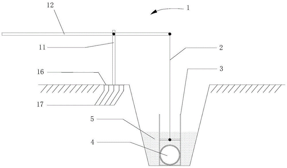
Fig. 1 is a schematic structural view of the auxiliary device for sanding an underground cable according to the embodiment.
Fig. 2 is a schematic structural view of the jig.
Fig. 3 is a schematic diagram of the hinge structure of two hinge arms.
Fig. 4 is a schematic structural view of the driving mechanism.
Illustration of the drawings: 1. a drive mechanism; 11. erecting a rod; 12. a lever; 13. a second hinge shaft; 14. a horizontal portion; 15. a vertical portion; 16. a support plate; 17. steel nails; 2. pulling a rope; 3. a clamp; 31. half holding clamp; 311. clamping arms; 312. a bracket arm; 313. an articulated arm; 314. an outer ring; 315. an inner ring; 32. a first hinge shaft; 4. an underground cable.
Detailed Description
The invention is further described below with reference to specific preferred embodiments, without thereby limiting the scope of protection of the invention.
Example (b):
as shown in fig. 1, the buried cable sanding auxiliary device of the present embodiment includes a driving mechanism 1, a pulling rope 2, and a clamp 3 for clamping or releasing a buried cable 4.
The clamp 3 comprises two half-clasping clamps 31 with opposite openings, the two half-clasping clamps 31 are hinged through a first hinge shaft 32 arranged along the axial direction of the buried cable 4, the lower end of the pull rope 2 is connected with the two half-clasping clamps 31, the upper end of the pull rope 2 is connected with the driving mechanism 1, the driving mechanism 1 can drive the pull rope 2 to lift so as to drive the two half-clasping clamps 31 to rotate around the first hinge shaft 32 to be closed so as to clamp the buried cable 4, and the driving mechanism 1 can drive the pull rope 2 to lower so as to drive the two half-clasping clamps 31 to rotate around the first hinge shaft 32 to be opened so as to loosen the buried cable 4.
Referring to fig. 2, the half clasping clamp 31 includes a clamping arm 311 for contacting with a side wall of the buried cable 4, a lower end of the clamping arm 311 is bent toward the other half clasping clamp 31 to form a supporting arm 312 for contacting with a bottom wall of the buried cable 4, and a hinged arm 313 extending toward the other half clasping clamp 31 is provided on the clamping arm 311. Referring to fig. 3, one of the hinge arms 313 is provided at an end thereof with an outer ring 314, the other hinge arm 313 is provided at an end thereof with an inner ring 315 fitted in the outer ring 314, the inner ring 315 and the outer ring 314 are rotatably connected to form a hinge bearing, and the inner ring 315 is provided therein with a first hinge shaft 32 to hinge the two hinge arms 313. The pull rope 2 is a steel strand, and the lower end of the pull rope 2 is wound on the hinged bearing.
With continued reference to fig. 1, the drive mechanism 1 comprises an upright 11, and a lever 12 hinged to the upper end of the upright 11. The lower end of the upright 11 is provided with a support plate 16 supported on the ground, and the bottom of the support plate 16 is provided with a plurality of steel nails 17 embedded in the foundation. The lever 12 is hinged to the vertical rod 11 through a second hinge shaft 13 arranged along the axial direction of the buried cable 4, and one end of the lever 12 facing the buried cable 4 is fixedly connected with the upper end of the pull rope 2.
Referring to fig. 4, a U-shaped member is disposed at an upper end of the vertical rod 11, the U-shaped member includes a horizontal portion 14 fixedly connected to the vertical rod 11, and two vertical portions 15 fixed to the horizontal portion 14, the two vertical portions 15 are disposed at two sides of the lever 12 in a radial direction, and a second hinge shaft 13 penetrates the two vertical portions 15 and the lever 12 to hinge the vertical rod 11 and the lever 12.
The working principle of the buried cable sand laying auxiliary device is as follows: clamping the cable by using a cable clamp; the steel strand penetrates through a central circular ring hole of the cable clamp and is connected and fastened with the end part of the T-shaped lifting lever; and a proper position is selected at the cable trench edge to firmly install the T-shaped lifting lever. After the procedure of laying sand on the cable is finished, the far end of the lever is pressed down to lift the pull rope, the pull rope pulls the clamp to drive the cable to move upwards, and sandy soil flows downwards due to self weight, so that the effect of laying sand on the upper/lower parts of the cable is achieved.
The invention relates to a novel auxiliary device for a sand paving procedure of an underground cable, which comprises the following specific manufacturing and using methods:
1. device manufacturing process
1) And manufacturing a T-shaped lever and a support. (see FIG. 1 and FIG. 2 for details.)
Preparing materials: 25 steel nails with the length of 100 mm; 1 square steel plate with the size of 400mm multiplied by 8 mm; 2 straight steel pipes with the length of 3200mm and 800mm respectively; 1U-shaped steel tube with the bottom side of 250mm and two side edges of 200 mm; 1 smooth round steel bar with the length of 150mm and the diameter of 20 mm;
the manufacturing process comprises the following steps: uniformly welding steel nails at the bottom of a square steel plate at intervals of 100mm multiplied by 100 mm; welding the 800mm straight steel pipe at the center of the top surface of the square steel plate; firmly welding the central point of the U-shaped steel pipe and the top end of the 800mm straight steel pipe; drilling a hole at the 1000mm position at one end of a 3200mm straight steel pipe, wherein the hole diameter is 22 mm; and inserting the smooth round steel bar into the drilled hole, and firmly welding the two ends of the smooth round steel bar and the two sides of the U-shaped steel pipe.
2) And manufacturing a cable clamp. (see FIG. 3, FIG. 4 for details)
Preparing materials: 2L-shaped steel bars with the length of 1000mm and 200mm and the diameter of 10mm are respectively arranged on two sides; 2 steel cross bars with the size of 200mm multiplied by 40mm multiplied by 10 mm; a, 1 inner steel ring is arranged, the radius of an outer circle is 14.9mm, the radius of an inner circle is 8mm, and the length is 20 mm; b, 1 outer steel ring, 20mm of outer circle radius, 15mm of inner circle radius and 20mm of length;
the manufacturing process comprises the following steps: embedding the A steel circular ring into the B steel circular ring, wherein the AB can rotate mutually; firmly welding the B steel ring and the 2 steel cross rods; and respectively welding the steel cross rods with the L-shaped steel bars, wherein the welding point is the center of the long edge.
3) And (4) steel strands. The length of the steel strand is 3m, and the length of the steel strand is adjusted according to the requirement when the steel strand is used.
4) Integral assembly
Preparing materials: manufactured T-shaped lever, support, cable clamp and steel strand
The assembling process comprises the following steps: and (3) penetrating the steel strand through a steel circular ring hole in the cable clamp, adjusting the length of the steel strand according to construction requirements, and then firmly connecting the steel strand with the short end of the T-shaped lever.
Instructions for use.
1) After the cable trench is dug, laying the cable, and then covering soil according to the required thickness;
2) selecting a proper position of the cable trench edge, vertically inserting the T-shaped lever strip steel nail base into soil and treading tightly;
3) clamping and fixing the cable by using a cable clamp;
4) force is applied to the long end of the lever, the lever is used for lifting the cable to a certain height, and fine sand flows into the lower part of the cable under the action of gravity;
5) and lifting the whole section of cable at intervals of 3m in sequence. Then, leveling the whole section of sand manually.
The above description is only for the preferred embodiment of the present application and should not be taken as limiting the present application in any way, and although the present application has been disclosed in the preferred embodiment, it is not intended to limit the present application, and those skilled in the art should understand that they can make various changes and modifications within the technical scope of the present application without departing from the scope of the present application, and therefore all the changes and modifications can be made within the technical scope of the present application.