Multifunctional cable test system and use method thereof
Technical Field
The invention belongs to the technical field of cable testing, and particularly relates to a multifunctional cable testing system and a using method thereof.
Background
In the power equipment, the smoothness of wired communication and the transmission of power depend on the normal operation of the cable line. Once a line is obstructed, communication and power interruption can be caused, and if the fault cannot be detected and eliminated quickly in time, great economic loss and adverse social effects can be caused. Thus, cable fault testers are an important tool for maintaining various cables. The cable fault tester is a set of comprehensive cable fault detection equipment, and is used for testing open circuit, short circuit, grounding, low resistance, high resistance flashover and high resistance leakage faults of a power cable and accurately testing open circuit and short circuit faults of a coaxial communication cable and a local telephone cable.
The capacitor capacity of the traditional high-voltage impact generator is fixed, the impact energy output by the high-voltage impact generator is enough when a cable with high voltage grade is tested, but the voltage output by the high-voltage impact generator cannot be too high when a low-voltage cable is tested, the impact energy output by the high-voltage impact generator is too small, a cable fault point is not easy to break down, the low-voltage cable fault test is difficult, and the special voltage impact generator for the low-voltage cable test needs to be purchased. Sometimes, it is very inconvenient to carry two kinds of voltage impact signal generators during field test, and the existing cable fault tester has single function and is very inconvenient to move, so that a set of multifunctional cable test system is formed, and the multifunctional cable test system is convenient for a user to use on the field.
Disclosure of Invention
The invention aims to: in order to solve the above-mentioned problems, a multifunctional cable testing system and a method for using the same are provided.
The technical scheme adopted by the invention is as follows: the multifunctional cable testing system comprises a damping, moving and fixing integrated mechanism, wherein the upper end of the damping, moving and fixing integrated mechanism is fixedly arranged on the outer wall of the bottom end of a cable testing box body, a distribution box is arranged on the outer side of the lower end of the cable testing box body, a handle is fixedly arranged at the top end of the cable testing box body, a signal lamp is arranged outside the left side of the upper end of the cable testing box body, a function selection button is arranged at the outer end of the cable testing box body and below the signal lamp, a switch button is arranged at the outer end of the cable testing box body and below the function selection button, a storage box is arranged on the left side of the switch button, a liquid crystal display screen is arranged at the upper end of the storage box, a pulse input interface is arranged at the left end of the storage box, the lower end of the voltage display screen is provided with a socket, the socket comprises a charging socket and a USB interface, and a test connecting line is arranged inside the storage box.
In a preferred embodiment, a data storage unit, a fault analysis unit, a control unit, a capacitance adjustment unit, a signal receiving module, a signal processing module, a power supply module, an adjustment module, a pulse generation unit, a data display module, an on-off test module and an insulation test module are integrated inside the cable test box body, the power supply module is connected with the socket, and the display unit is connected with the voltage display screen and the liquid crystal display screen.
In a preferred embodiment, the on-off test module and the insulation test module are connected with a test connecting line arranged inside the storage box, the adjusting module is connected with the adjusting knob, the tested cable is connected with the pulse input interface and the test connecting line, the on-off test module and the insulation test module are electrically connected with a data storage unit, and the data storage unit is electrically connected with a fault analysis unit.
In a preferred embodiment, the fault analysis unit is electrically connected to the control unit and the data display module, the control unit is electrically connected to the pulse generation unit, the pulse generation unit is electrically connected to the capacitance adjustment unit, the capacitance adjustment unit is electrically connected to the power supply module, the adjustment module and the capacitance adjustment unit, the capacitance adjustment unit is electrically connected to the signal receiving module, the signal receiving module is electrically connected to the signal processing module, and the signal processing module is electrically connected to the data display module.
In a preferred embodiment, the fixed integration mechanism of shock attenuation removal includes universal wheel, support base, connecting rod, spring beam, sleeve pipe and screw thread seat, spring beam upper end is through connecting seat fixed mounting in cable test box bottom, spring beam movable mounting is on the sleeve pipe, the sleeve pipe bottom is through connecting plate fixedly connected with connecting rod, the connecting rod is close to the one end at cable test box middle part and has seted up the screw thread seat, threaded mounting has the support base on the screw thread seat, the connecting rod is kept away from the one end movable mounting at cable test box center and has the universal wheel.
In a preferred embodiment, the socket is electrically connected with an input end of an alternating current 22OV power supply, the alternating current 22OV power supply is electrically connected with an input end of an alternating current voltage regulator, and the alternating current voltage regulator is electrically connected with input ends of a first direct current high voltage generator, a second direct current high voltage generator, a third direct current high voltage generator and a fourth direct current high voltage generator.
In a preferred embodiment, the first dc high voltage generator is electrically connected to the first high voltage capacitor input, the second dc high voltage generator is electrically connected to the second high voltage capacitor input, the third dc high voltage generator is electrically connected to the third high voltage capacitor input, and the fourth dc high voltage generator is electrically connected to the fourth high voltage capacitor input.
In a preferred embodiment, the fourth high voltage capacitor, the third high voltage capacitor, the second high voltage capacitor and the first high voltage capacitor are electrically connected to the input ends of the capacitance switching static disc and the capacitance switching dynamic disc.
In a preferred embodiment, the first dc high voltage generator, the second dc high voltage generator, the third dc high voltage generator and the fourth dc high voltage generator are electrically connected to an input end of a high voltage meter, the high voltage meter is electrically connected to a high voltage output power source, the high voltage output power source is electrically connected to a high voltage discharge switch, the high voltage discharge switch is electrically connected to a resistor, and the resistor is electrically connected to the high voltage meter.
In a preferred embodiment, the input voltage of the cable test box body is 220V50Hz, the maximum power of the cable test box body is 1.5kW, the sampling frequency of the cable test box body is 200MHz, the maximum distance measurement distance of the cable test box body is 32kM, and the total weight of the cable test box body is 50 Kg.
The use method of the multifunctional cable test system comprises the following steps:
the method comprises the following steps: before the cable test box is used, the position of the device is adjusted, the position of the supporting base is adjusted in the reverse direction, when the height of the supporting base is higher than that of the universal wheel, the device can be driven to move through the universal wheel, in the moving process, the pressure applied to the device in the moving process can be reduced through the cooperation of the spring rod and the sleeve, the damping effect of the device is improved, the possibility of damage of internal electronic elements is reduced, when the position is adjusted, the position of the supporting base is adjusted in the forward direction, when the low degree of the supporting base is higher than that of the universal wheel, the cable test box can be fixed through the supporting base, meanwhile, the cable test box is conveniently lifted through the handle, and the cable test box is small in size, light in weight and convenient to move and carry;
step two: the 220v alternating current power supply is inserted through the socket, then the tested cable is connected with the test connecting line, the fault reason of the tested cable is detected through the on-off test module and the insulation test module, then the fault reason is analyzed through the fault analysis unit, and then the fault reason is displayed through the liquid crystal display screen connected with the data display module;
step three: when cables with different voltage grades need to be tested, when the capacitance switching static disc and the capacitance switching movable disc are rotated to correspond to each other, the fourth high-voltage capacitor, the third high-voltage capacitor, the second high-voltage capacitor and the first high-voltage capacitor are connected in parallel, the capacity is 128uF, the output voltage is at most 8kv, when the adjusting knob is rotated, when the capacitance switching static disc and the capacitance switching movable disc rotate 30 degrees clockwise from the positioning points, the fourth high-voltage capacitor and the second high-voltage capacitor are connected in parallel, the third high-voltage capacitor and the first high-voltage capacitor are connected in parallel, then the fourth high-voltage capacitor and the second high-voltage capacitor are connected in series with the third high-voltage capacitor and the first high-voltage capacitor, the capacity is 32uF, the output voltage is at most 16kv, when the capacitance switching static disc and the capacitance switching movable disc rotate 60 degrees clockwise from the positioning points, the fourth high-voltage capacitor, the third high-, The second high-voltage capacitor and the first high-voltage capacitor are all connected in series, the capacity is 8uF, the output voltage is at most 32kv, and different switching of voltages is realized;
step four: the high-voltage discharge switch and the resistor can discharge for the fourth high-voltage capacitor, the third high-voltage capacitor, the second high-voltage capacitor and the first high-voltage capacitor, after all capacitors are discharged, the fourth high-voltage capacitor, the third high-voltage capacitor, the second high-voltage capacitor and the first high-voltage capacitor can be switched, the high-voltage voltmeter can display the numerical value of the output voltage, after the capacitors are adjusted, the data of the tested cable is displayed through the data display module, and the test flow of the cable is finished.
In summary, due to the adoption of the technical scheme, the invention has the beneficial effects that:
1. according to the invention, the matching of the spring rod and the sleeve can reduce the pressure applied to the device in the moving process, so that the damping effect of the device is improved, and the possibility of damaging internal electronic elements is reduced.
2. According to the cable testing box, the position of the supporting base is adjusted in the forward direction, when the supporting base is higher than the universal wheels, the cable testing box can be fixed through the supporting base, the position of the supporting base is adjusted in the reverse direction, and when the supporting base is higher than the universal wheels, the device can be driven to move through the universal wheels, so that the device can be conveniently moved, installed and fixed, and the cable testing box is small in size, light in weight and convenient to move and transport.
3. According to the invention, the rotation of the capacitance switching static disc and the capacitance switching movable disc is realized by rotating the regulating knob, then different connection modes of the fourth high-voltage capacitor, the second high-voltage capacitor, the third high-voltage capacitor and the first high-voltage capacitor are realized according to the rotation of the capacitance switching static disc and the capacitance switching movable disc, and the change of the capacity and the output voltage is realized according to the different connection modes of the fourth high-voltage capacitor, the second high-voltage capacitor, the third high-voltage capacitor and the first high-voltage capacitor, so that the quick fixed point of the power cable suitable for different voltage grades is realized.
4. According to the invention, the high-voltage discharge switch and the resistor can discharge the fourth high-voltage capacitor, the second high-voltage capacitor, the third high-voltage capacitor and the first high-voltage capacitor, the fourth high-voltage capacitor, the second high-voltage capacitor, the third high-voltage capacitor and the first high-voltage capacitor can be switched after all capacitors are discharged, and the tested cable and the internal capacitor can be automatically discharged after the equipment is disconnected, so that the safety of the device is improved.
5. The tested cable is connected with the test connecting line, fault reasons of the tested cable are detected through the on-off test module and the insulation test module, then the fault reasons are analyzed through the fault analysis unit, then the fault reasons are displayed through the liquid crystal display screen connected with the data display module, automatic analysis of the tested cable is achieved, data can be displayed through the liquid crystal display screen, and the intelligence of the device is improved.
Drawings
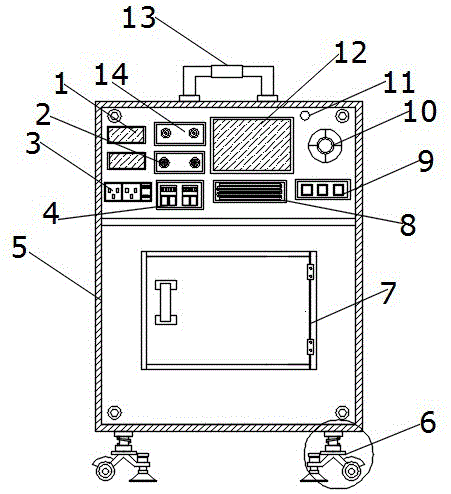
FIG. 1 is a schematic structural view of the present invention;
FIG. 2 is an enlarged schematic diagram of the damping, moving and fixing integrated mechanism of the present invention;
FIG. 3 is a schematic diagram of the system architecture for capacitance tuning of the present invention;
FIG. 4 is a functional block diagram of the cable test of the present invention;
FIG. 5 is a schematic diagram of the electric switching rotor configuration of the present invention.
The labels in the figure are: 1-a voltage display screen, 2-a regulation knob, 3-a socket, 4-a pulse input interface, 5-a cable test box body, 6-a damping moving and fixing integrated mechanism, 601-a spring rod, 602-a sleeve, 603-a connecting rod, 604-a universal wheel, 605-a supporting base, 606-a threaded base, 7-a distribution box, 8-a storage box, 9-a switch button, 10-a function selection button, 11-a signal lamp, 12-a liquid crystal display screen, 13-a handle, 14-a current input interface, 15-a signal processing module, 16-a signal receiving module, 17-a capacitance adjusting unit, 18-a pulse generating unit, 19-a power supply module, 20-a control unit, 21-a fault analyzing unit, 22-a data storage unit, 23-an insulation test module, 24-a tested cable, 25-an on-off test module, 26-a data display module, 27-a high-voltage voltmeter, 28-a third high-voltage capacitor, 29-a first high-voltage capacitor, 30-a third direct-current high-voltage generator, 31-a fourth direct-current high-voltage generator, 32-a second direct-current high-voltage generator, 33-a first direct-current high-voltage generator, 34-an alternating-current voltage regulator, 35-an alternating-current 22OV power supply, 36-a resistor, 37-a high-voltage discharge switch, 38-a high-voltage output power supply, 39-a capacitance switching static disc, 40-a second high-voltage capacitor, 41-a fourth high-voltage capacitor, 42-a capacitance switching dynamic disc and 43-a regulation module.
Detailed Description
In order to make the objects, technical solutions and advantages of the present invention more apparent, the present invention is described in further detail below with reference to the accompanying drawings and embodiments. It should be understood that the specific embodiments described herein are merely illustrative of the invention and are not intended to limit the invention.
Referring to fig. 1-5, the multifunctional cable testing system comprises a damping, moving and fixing integrated mechanism 6, the upper end of the damping, moving and fixing integrated mechanism 6 is fixedly installed on the outer wall of the bottom end of a cable testing box 5, the outer side of the lower end of the cable testing box 5 is provided with a distribution box 7, the top end of the cable testing box 5 is fixedly provided with a handle 13, the left outer side of the upper end of the cable testing box 5 is provided with a signal lamp 11, the lower side of the signal lamp 11 is provided with a function selection button 10 at the outer end of the cable testing box 5, the lower side of the function selection button 10 is provided with a switch button 9 at the outer end of the cable testing box 5, the left side of the switch button 9 is provided with a storage box 8, the upper end of the storage box 8 is provided with a liquid crystal display screen 12, the fault cause is displayed, the upper side of the regulation knob 2 is provided with a current input interface 14, the regulation knob 2 rotates to regulate the capacitance switching static disc 39 and the capacitance switching dynamic disc 42, the change of capacity and output voltage is realized, the left side of the current input interface 14 is provided with a voltage display screen 1, the lower end of the voltage display screen 1 is provided with a socket 3, the socket 3 comprises a charging socket and a USB interface, a test connecting wire is arranged inside the storage box 8, a 220v alternating current power supply is inserted through the socket 3, and then the tested cable 24 is connected with the test connecting wire.
It should be noted that the cable testing box 5 is internally integrated with a data storage unit 22, a fault analysis unit 21, a control unit 20, a capacitance adjustment unit 17, a signal receiving module 16, a signal processing module 15, a power supply module 19, an adjustment module 43, a pulse generation unit 18, a data display module 26, an on-off testing module 25 and an insulation testing module 23, the power supply module 19 is connected with the socket 3, and the display unit is connected with the voltage display screen 1 and the liquid crystal display screen 12.
It should be noted that the on-off test module 25 and the insulation test module 23 are connected to a test connection line arranged inside the storage box 8, the adjusting module 43 is connected to the adjusting knob 2, the tested cable 24 is connected to the pulse input interface 4 and the test connection line, the on-off test module 25 and the insulation test module 23 are electrically connected to the data storage unit 22, the data storage unit 22 is electrically connected to the fault analysis unit 21, the fault reason of the tested cable 24 is detected through the on-off test module 25 and the insulation test module 23, and then the fault reason is analyzed through the fault analysis unit 21.
It should be noted that the fault analysis unit 21 is electrically connected to the control unit 20 and the data display module 26, the control unit 20 is electrically connected to the pulse generation unit 18, the pulse generation unit 18 is electrically connected to the capacitance adjustment unit 17, the capacitance adjustment unit 17 is electrically connected to the power supply module 19, the adjustment module 43 and the capacitance adjustment unit 17, the capacitance adjustment unit 17 is electrically connected to the signal receiving module 16, the signal receiving module 16 is electrically connected to the signal processing module 15, and the signal processing module 15 is electrically connected to the data display module 26.
It should be noted that, fixed integration mechanism 6 is removed in shock attenuation includes universal wheel 604, support base 605, connecting rod 603, spring beam 601, sleeve pipe 602 and screw thread seat 606, spring beam 601 upper end is through connecting seat fixed mounting in cable test box 5 bottom, spring beam 601 movable mounting is on sleeve pipe 602, sleeve pipe 602 bottom is through connecting plate fixedly connected with connecting rod 603, threaded seat 606 has been seted up to the one end that connecting rod 603 is close to cable test box 5 middle part, threaded mounting has support base 605 on the threaded seat 606, the one end movable mounting that connecting rod 603 kept away from cable test box 5 center has universal wheel 604.
It should be noted that the socket 3 is electrically connected to an input terminal of an ac 22OV power source 35, the ac 22OV power source 35 is electrically connected to an input terminal of an ac voltage regulator 34, and the ac voltage regulator 34 is electrically connected to input terminals of a first dc high voltage generator 33, a second dc high voltage generator 32, a third dc high voltage generator 30, and a fourth dc high voltage generator 31.
It should be noted that the first dc high voltage generator 33 is electrically connected to the input terminal of the first high voltage capacitor 29, the second dc high voltage generator 32 is electrically connected to the input terminal of the second high voltage capacitor 40, the third dc high voltage generator 30 is electrically connected to the input terminal of the third high voltage capacitor 28, the fourth dc high voltage generator 31 is electrically connected to the input terminal of the fourth high voltage capacitor 41, the capacity is 128uF and the output voltage is at most 8kv through the fourth high voltage capacitor 41, the third high voltage capacitor 28, the second high voltage capacitor 40 and the first high voltage capacitor 29 being connected in parallel, when the regulation knob 2 is rotated, when the capacitance switching stator 39 and the capacitance switching rotor 42 are rotated clockwise by 30 degrees from the positioning point, the fourth high voltage capacitor 41 and the second high voltage capacitor 40 are connected in parallel, the third high voltage capacitor 28 and the first high voltage capacitor 29 are connected in parallel, then the fourth high voltage capacitor 41 and the second high voltage capacitor 40 are connected in series with the third high voltage capacitor 28 and the first high voltage capacitor 29, the capacity is 32uF, the output voltage is 16kv at most, when the capacitance switching static disc 39 and the capacitance switching dynamic disc 42 rotate 60 degrees clockwise from the positioning points, the fourth high-voltage capacitor 41, the third high-voltage capacitor 28, the second high-voltage capacitor 40 and the first high-voltage capacitor 29 are all connected in series, the capacity is 8uF, the output voltage is 32kv at most, and different switching of voltages is realized.
It should be noted that the fourth high-voltage capacitor 41, the third high-voltage capacitor 28, the second high-voltage capacitor 40, and the first high-voltage capacitor 29 are electrically connected to the input ends of the capacitance switching static plate 39 and the capacitance switching dynamic plate 42.
It should be noted that, the first dc high voltage generator 33, the second dc high voltage generator 32, the third dc high voltage generator 30 and the fourth dc high voltage generator 31 are electrically connected to the input end of the high voltage voltmeter 27, the high voltage voltmeter 27 is electrically connected to the high voltage output power source 38, the high voltage voltmeter 27 can display the value of the output voltage, the high voltage output power source 38 is electrically connected to the high voltage discharge switch 37, the high voltage discharge switch 37 is electrically connected to the resistor 36, the resistor 36 is electrically connected to the high voltage voltmeter 27, the high voltage discharge switch 37 and the resistor 36 can discharge the fourth high voltage capacitor 41, the third high voltage capacitor 28, the second high voltage capacitor 40 and the first high voltage capacitor 29, after all the capacitors are discharged, the fourth high voltage capacitor 41, the third high voltage capacitor 28, the second high voltage capacitor 40 and the first high voltage capacitor 29 can be switched.
It should be noted that the input voltage of the cable testing box 5 is 220V50Hz, the maximum power of the cable testing box 5 is 1.5kW, the sampling frequency of the cable testing box 5 is 200MHz, the maximum distance measurement distance of the cable testing box 5 is 32kM, and the total weight of the cable testing box 5 is 50 Kg.
The use method of the multifunctional cable test system comprises the following steps:
the method comprises the following steps: before the cable test box is used, firstly, the position of the device is adjusted, the position of the support base 605 is adjusted in the reverse direction, when the height of the support base 605 is higher than that of the universal wheel 604, the device can be driven to move through the universal wheel 604, in the moving process, the pressure applied to the device in the moving process can be reduced through the matching of the spring rod 601 and the sleeve 602, the damping effect of the device is improved, the possibility of damaging an internal electronic element is reduced, when the position adjustment is finished, the position of the support base 605 is adjusted in the forward direction, when the height of the support base 605 is higher than that of the universal wheel 604, the cable test box 5 can be fixed through the support base 605, meanwhile, the cable test box 5 is conveniently lifted through the handle 13, and the cable test box 5 is small in size, light in weight and convenient to move and transport;
step two: a 220v alternating current power supply is inserted through the socket 3, then the tested cable 24 is connected with a test connecting line, the fault reason of the tested cable 24 is detected through the on-off test module 25 and the insulation test module 23, then the fault reason is analyzed through the fault analysis unit 21, and then the fault reason is displayed through the liquid crystal display 12 connected with the data display module 26;
step three: when cables with different voltage grades need to be tested, when the positioning points of the rotating capacitance switching static disc 39 and the capacitance switching movable disc 42 correspond, the capacity is 128uF and the output voltage is 8kv at most through the parallel connection of the fourth high-voltage capacitor 41, the third high-voltage capacitor 28, the second high-voltage capacitor 40 and the first high-voltage capacitor 29, when the capacitance switching static disc 39 and the capacitance switching movable disc 42 rotate 30 DEG clockwise from the positioning points when the adjusting knob 2 is rotated, the fourth high-voltage capacitor 41 and the second high-voltage capacitor 40 are connected in parallel, the third high-voltage capacitor 28 and the first high-voltage capacitor 29 are connected in parallel, then the fourth high-voltage capacitor 41 and the second high-voltage capacitor 40 are connected in series with the third high-voltage capacitor 28 and the first high-voltage capacitor 29, the capacity is 32uF and the output voltage is 16kv at most, when the capacitance switching static disc 39 and the capacitance switching movable disc 42 rotate 60 DEG clockwise from the positioning points, the fourth high-voltage capacitor 41, the third high-voltage capacitor 28, the second high-voltage capacitor 40 and the first high-voltage capacitor 29 are all connected in series, the capacity is 8uF, the output voltage is at most 32kv, and different switching of voltages is realized;
step four: the ac voltage regulator 34 is used to regulate the charging voltage of the first dc high voltage generator 33, the second dc high voltage generator 32, the third dc high voltage generator 30 and the fourth dc high voltage generator 31, the high voltage discharge switch 37 and the resistor 36 can discharge the fourth high voltage capacitor 41, the third high voltage capacitor 28, the second high voltage capacitor 40 and the first high voltage capacitor 29, after all the capacitors are discharged, the fourth high voltage capacitor 41, the third high voltage capacitor 28, the second high voltage capacitor 40 and the first high voltage capacitor 29 can be switched, the high voltage voltmeter 27 can display the value of the output voltage, and after the capacitors are regulated, the data of the cable to be tested is displayed through the data display module 26, and the testing process of the cable is finished.
The working principle is as follows:
before the cable test box body 5 is used, firstly, the position of the device is adjusted, the position of the support base 605 is adjusted in the reverse direction, when the height of the support base 605 is higher than that of the universal wheel 604, the device can be driven to move through the universal wheel 604, in the moving process, the pressure applied to the device in the moving process can be reduced through the matching of the spring rod 601 and the sleeve 602, the damping effect of the device is improved, the possibility of damaging an internal electronic element is reduced, when the position adjustment is finished, the position of the support base 605 is adjusted in the forward direction, when the height of the support base 605 is higher than that of the universal wheel 604, the cable test box body 5 can be fixed through the support base 605, meanwhile, the cable test box body 5 is convenient to lift through the handle 13, and the cable test box body 5 is small in size, light in weight and convenient to move.
When the device is used, firstly, a 220v alternating current power supply is inserted through the socket 3, then the tested cable 24 is connected with a test connecting line, the fault reason of the tested cable 24 is detected through the on-off test module 25 and the insulation test module 23, then the fault reason is analyzed through the fault analysis unit 21, then the fault reason is displayed through the liquid crystal display 12 connected with the data display module 26, when cables with different voltage levels need to be tested, when the capacitance switching static disc 39 and the capacitance switching dynamic disc 42 correspond to each other in positioning point, the fourth high-voltage capacitor 41, the third high-voltage capacitor 28, the second high-voltage capacitor 40 and the first high-voltage capacitor 29 are connected in parallel, the capacity is 128uF, the output voltage is at most 8kv, when the regulation knob 2 is rotated, when the capacitance switching static disc 39 and the capacitance switching dynamic disc 42 are rotated 30 degrees clockwise from the positioning point, a fourth high voltage capacitor 41 and a second high voltage capacitor 40 are connected in parallel, a third high voltage capacitor 28 and a first high voltage capacitor 29 are connected in parallel, then the fourth high voltage capacitor 41 and the second high voltage capacitor 40 are connected in series with the third high voltage capacitor 28 and the first high voltage capacitor 29, the capacity is 32uF, the output voltage is 16kv at most, when the capacitance switching static disc 39 and the capacitance switching dynamic disc 42 are rotated 60 degrees clockwise from the positioning points, the fourth high voltage capacitor 41, the third high voltage capacitor 28, the second high voltage capacitor 40 and the first high voltage capacitor 29 are all connected in series, the capacity is 8uF, the output voltage is 32kv at most, different switching of the voltages is realized, an AC voltage regulator 34 is used for adjusting the charging voltages of the first DC high voltage generator 33, the second DC high voltage generator 32, the third DC high voltage generator 30 and the fourth DC high voltage generator 31, a high voltage discharge switch 37 and a resistor 36 can supply the fourth high voltage capacitor 41, the second DC high voltage capacitor 32, the third DC high voltage capacitor 28, The third high-voltage capacitor 28, the second high-voltage capacitor 40 and the first high-voltage capacitor 29 are discharged, after all the capacitors are discharged, the fourth high-voltage capacitor 41, the third high-voltage capacitor 28, the second high-voltage capacitor 40 and the first high-voltage capacitor 29 can be switched, the high-voltage voltmeter 27 can display the numerical value of the output voltage, after the capacitors are adjusted, the data of the tested cable is displayed through the data display module 26, and the testing process of the cable is finished.
The above description is only for the purpose of illustrating the preferred embodiments of the present invention and is not to be construed as limiting the invention, and any modifications, equivalents and improvements made within the spirit and principle of the present invention are intended to be included within the scope of the present invention.