CN112723604A - High efficiency air supporting water purification unit - Google Patents
High efficiency air supporting water purification unit Download PDFInfo
- Publication number
- CN112723604A CN112723604A CN202110019019.0A CN202110019019A CN112723604A CN 112723604 A CN112723604 A CN 112723604A CN 202110019019 A CN202110019019 A CN 202110019019A CN 112723604 A CN112723604 A CN 112723604A
- Authority
- CN
- China
- Prior art keywords
- air
- fixedly connected
- driving motor
- pipe
- top end
- Prior art date
- Legal status (The legal status is an assumption and is not a legal conclusion. Google has not performed a legal analysis and makes no representation as to the accuracy of the status listed.)
- Pending
Links
- XLYOFNOQVPJJNP-UHFFFAOYSA-N water Substances O XLYOFNOQVPJJNP-UHFFFAOYSA-N 0.000 title claims abstract description 93
- 238000000746 purification Methods 0.000 title claims abstract description 27
- 238000005188 flotation Methods 0.000 claims abstract description 45
- 230000005540 biological transmission Effects 0.000 claims abstract description 31
- 239000002893 slag Substances 0.000 claims abstract description 18
- 238000003756 stirring Methods 0.000 claims abstract description 16
- 238000009434 installation Methods 0.000 claims description 14
- 230000006837 decompression Effects 0.000 claims description 6
- 238000007790 scraping Methods 0.000 claims description 4
- 238000007599 discharging Methods 0.000 claims description 3
- 239000013049 sediment Substances 0.000 claims 3
- 239000003818 cinder Substances 0.000 claims 1
- 238000005189 flocculation Methods 0.000 abstract description 5
- 230000016615 flocculation Effects 0.000 abstract description 4
- 239000012535 impurity Substances 0.000 description 14
- 239000010865 sewage Substances 0.000 description 11
- 239000008394 flocculating agent Substances 0.000 description 9
- 230000005484 gravity Effects 0.000 description 5
- 239000003814 drug Substances 0.000 description 4
- 230000000694 effects Effects 0.000 description 4
- 230000001105 regulatory effect Effects 0.000 description 4
- 238000010586 diagram Methods 0.000 description 2
- 238000000034 method Methods 0.000 description 2
- FGRBYDKOBBBPOI-UHFFFAOYSA-N 10,10-dioxo-2-[4-(N-phenylanilino)phenyl]thioxanthen-9-one Chemical compound O=C1c2ccccc2S(=O)(=O)c2ccc(cc12)-c1ccc(cc1)N(c1ccccc1)c1ccccc1 FGRBYDKOBBBPOI-UHFFFAOYSA-N 0.000 description 1
- 229940037003 alum Drugs 0.000 description 1
- 230000001174 ascending effect Effects 0.000 description 1
- 230000009286 beneficial effect Effects 0.000 description 1
- 238000005345 coagulation Methods 0.000 description 1
- 230000015271 coagulation Effects 0.000 description 1
- 238000004891 communication Methods 0.000 description 1
- 239000003344 environmental pollutant Substances 0.000 description 1
- 230000003311 flocculating effect Effects 0.000 description 1
- 239000007788 liquid Substances 0.000 description 1
- 238000004519 manufacturing process Methods 0.000 description 1
- 230000004048 modification Effects 0.000 description 1
- 238000012986 modification Methods 0.000 description 1
- 238000005192 partition Methods 0.000 description 1
- 231100000719 pollutant Toxicity 0.000 description 1
- 238000000926 separation method Methods 0.000 description 1
- 239000000126 substance Substances 0.000 description 1
- 239000008400 supply water Substances 0.000 description 1
- 239000002351 wastewater Substances 0.000 description 1
Images


Classifications
-
- C—CHEMISTRY; METALLURGY
- C02—TREATMENT OF WATER, WASTE WATER, SEWAGE, OR SLUDGE
- C02F—TREATMENT OF WATER, WASTE WATER, SEWAGE, OR SLUDGE
- C02F1/00—Treatment of water, waste water, or sewage
- C02F1/24—Treatment of water, waste water, or sewage by flotation
-
- C—CHEMISTRY; METALLURGY
- C02—TREATMENT OF WATER, WASTE WATER, SEWAGE, OR SLUDGE
- C02F—TREATMENT OF WATER, WASTE WATER, SEWAGE, OR SLUDGE
- C02F1/00—Treatment of water, waste water, or sewage
- C02F1/52—Treatment of water, waste water, or sewage by flocculation or precipitation of suspended impurities
- C02F1/5281—Installations for water purification using chemical agents
-
- C—CHEMISTRY; METALLURGY
- C02—TREATMENT OF WATER, WASTE WATER, SEWAGE, OR SLUDGE
- C02F—TREATMENT OF WATER, WASTE WATER, SEWAGE, OR SLUDGE
- C02F2201/00—Apparatus for treatment of water, waste water or sewage
- C02F2201/002—Construction details of the apparatus
-
- C—CHEMISTRY; METALLURGY
- C02—TREATMENT OF WATER, WASTE WATER, SEWAGE, OR SLUDGE
- C02F—TREATMENT OF WATER, WASTE WATER, SEWAGE, OR SLUDGE
- C02F2201/00—Apparatus for treatment of water, waste water or sewage
- C02F2201/002—Construction details of the apparatus
- C02F2201/004—Seals, connections
-
- C—CHEMISTRY; METALLURGY
- C02—TREATMENT OF WATER, WASTE WATER, SEWAGE, OR SLUDGE
- C02F—TREATMENT OF WATER, WASTE WATER, SEWAGE, OR SLUDGE
- C02F2209/00—Controlling or monitoring parameters in water treatment
- C02F2209/40—Liquid flow rate
-
- C—CHEMISTRY; METALLURGY
- C02—TREATMENT OF WATER, WASTE WATER, SEWAGE, OR SLUDGE
- C02F—TREATMENT OF WATER, WASTE WATER, SEWAGE, OR SLUDGE
- C02F2303/00—Specific treatment goals
- C02F2303/14—Maintenance of water treatment installations
Abstract
The invention provides a high-efficiency air-flotation water purification device, which comprises a treatment tank and an air-flotation tank, wherein one side of the treatment tank is fixedly connected with the air-flotation tank, the top end of the treatment tank is fixedly connected with a stirring mechanism, one side of the air-flotation tank is provided with a slag discharge groove, the top end of the air-flotation tank is fixedly connected with a slag discharge mechanism, one side of the top end of the air-flotation tank is fixedly connected with a support plate, the back of the top end of the support plate is fixedly connected with a fixed block, the top end of the fixed block is fixedly connected with a first driving motor, an output shaft of the first driving motor is fixedly connected with a driving gear, the driving gear is in transmission connection with the slag discharge: through the pipe chute that is equipped with, increase air supporting area is that micro-bubble avoids going on under turbulent state, makes good laminar flow state for bubble and the better adhesion of flocculation thing, the effectual efficiency that improves the air supporting and purify.
Description
Technical Field
The invention relates to the technical field of water purification equipment, in particular to high-efficiency air-flotation water purification equipment.
Background
The air flotation device firstly enters raw water into a mixing reactor, a medicament is added into the mixing reactor to form separable flocs, pretreated sewage enters the air flotation device, a large amount of air is dissolved in the water under certain conditions to form air-dissolved water as a working medium, the air-dissolved water is condensed and decompressed through a releaser, a large amount of micro-bubbles are quickly released and generated to be adhered to alum flocs of the waste water after coagulation reaction, the micro-bubbles are adhered to the flocs in the sewage to form an air floating body with the specific gravity smaller than that of the water so as to float the flocs, the air floating body rises to the water surface to be condensed into floating oil (or scum) according to the buoyancy principle, the floating oil (scum) is scraped to an oil (scum) collecting tank through an oil (scum) scraping machine, solid-liquid separation is realized, and the sewage is purified, and the existing air flotation water purification equipment:
(1) when the existing air-flotation water purification equipment is used for air-flotation purification of a water body, the contact time of bubbles and flocculated impurities is short, so that the bubbles cannot be well adhered to the impurities, the air-flotation purification time of sewage is long, and the production input cost of enterprises is increased invisibly;
(2) when carrying out the flocculation process to sewage, flocculate to the raw water in the reaction tank through charge device, but because the great reason of equipment volume, the medicament is inhomogeneous with the raw water contact, leads to flocculating the effect poor.
Disclosure of Invention
The invention aims to provide high-efficiency air-flotation water purification equipment, aiming at the problems that the air-flotation purification time is long and the contact time of micro bubbles and impurities is short in the prior art; the medicament is not uniformly contacted with raw water due to large equipment volume in the dosing process, and the flocculation effect is poor.
In order to achieve the purpose, the invention provides the following technical scheme: a high-efficiency air-flotation water purification device comprises a treatment tank and an air-flotation tank, wherein the air-flotation tank is fixedly connected to one side of the treatment tank, a stirring mechanism is fixedly connected to the top end of the treatment tank, a deslagging groove is formed in one side of the air-flotation tank, a baffle is fixedly connected to the bottom end of the air-flotation tank at one side of the deslagging groove, a groove is formed in the middle of the top end of the baffle, a deslagging mechanism is fixedly connected to the top end of the air-flotation tank, a support plate is fixedly connected to one side of the top end of the support plate, a fixed block is fixedly connected to the back of the top end of the support plate, a first driving motor is fixedly connected to the top end of the fixed block, an output shaft of the first driving motor is fixedly connected with a driving gear, the driving gear is in transmission connection with the deslagging mechanism, a, first communicating pipe and the installation of the end intercommunication of intaking of water pump, the play water end and the installation of second communicating pipe intercommunication of water pump, the second communicating pipe still with air supporting pond one side outer wall bottom intercommunication installation, it is provided with the air compressor machine to handle pond one side, the gas outlet and the pressure of air compressor machine dissolve gas pitcher intercommunication installation, pressure dissolves the gas pitcher bottom and passes through the decompression pipe and air supporting pond intercommunication installation, the relief pressure valve is installed at decompression pipe top, pressure dissolves the gas pitcher and openly still feeds through and installs the inlet tube, air supporting pond middle part fixedly connected with baffle, baffle surface equidistance evenly alternates and is connected with a plurality of pipe chute, baffle and scum groove bottom fixed connection, the air supporting pond is close to first driving motor one side lateral wall fixedly connected with flush.
In order to sufficiently stir the chemical and the raw water, a preferable embodiment of the present invention is: the stirring mechanism comprises a connecting plate fixedly connected to the top end of the treatment pool, a second driving motor is fixedly connected to the top end of the connecting plate through a motor support, and an output shaft of the second driving motor penetrates through the connecting plate and is fixedly connected with a stirring rod located inside the treatment pool.
In order to filter the resulting air-floating body, as a preferred embodiment of the present invention: the slag discharging mechanism comprises four bearing fixing seats fixedly connected to the top end of the air floatation tank, wherein the bearing fixing seats are located at the same side, a transmission rod is rotatably connected between the bearing fixing seats, two transmission rods are rotatably connected between the two transmission rods, the top ends of one sides of the two transmission belts and the bottom end of the other side of the two transmission belts are fixedly connected with scraping plates, the scraping plates are close to one ends of the transmission rods of the first driving motors, and the driven gears are in transmission connection with driving gears through chains.
In order to adjust the flow rate of the purified clean water, as a preferable scheme of the invention: flow control mechanism includes fixed connection in the rotation mount on backup pad top, rotate mount and threaded rod threaded connection, threaded rod top fixedly connected with hand runner, the threaded rod bottom runs through backup pad and adjusting plate top fixed connection's bearing frame and rotates and be connected, adjusting plate and the sealed sliding connection of fluting.
In order to supply water to the treatment tank and discharge purified clean water from the air flotation tank, the invention is a preferable scheme that: and the bottom end of the side wall of the treatment tank is communicated with and provided with a raw water pipe, and the bottom end of the side wall of the air flotation tank, which is just opposite to the raw water pipe, is communicated with and provided with a clear water pipe.
In order to remove impurities generated in the purification process, as a preferred embodiment of the present invention: the air floatation tank is characterized in that a deslagging pipe is communicated with and mounted on the side wall of the front side of the air floatation tank and is located at the bottom of a deslagging groove, and blowdown pipes are communicated with and mounted on two sides of the bottom of the side wall of the front side of the air floatation tank.
In order to make the equipment work normally, the invention adopts a preferable scheme that: the second driving motor, the first driving motor, the air compressor and the water pump are respectively electrically connected with the external power supply through a second driving motor control switch, a first driving motor control switch, an air compressor control switch and a water pump control switch on the switch panel, and the switch panel is electrically connected with the external power supply.
Compared with the prior art, the high-efficiency air-flotation water purification equipment provided by the invention has the following beneficial effects:
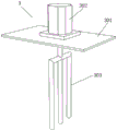
1) through the inclined tube, a large amount of micro bubbles generated by gas dissolving water released by the pressure reducing tube are adhered to flocculent impurities floating in the air floatation tank, so that flocculent air floating bodies float on the surface of a water body, the air floating bodies are removed through the slag discharging mechanism, and the air floatation area is increased through the inclined tube, so that the micro bubbles are prevented from being carried out in a turbulent flow state, a good laminar flow state is manufactured, the air floatation purification efficiency is effectively improved, and meanwhile, pollutants with large specific gravity and difficult to float upwards can be concentrated and precipitated at the bottom end of the air floatation tank through the inclined tube, so that the purpose of purifying water is achieved;
2) through the rabbling mechanism that is equipped with, back when the processing pond pours into the raw water into, need pour into former aquatic with the flocculating agent through medicine mechanism, flocculate through the impurity of flocculating agent with former aquatic, carry out intensive mixing through second driving motor drive stirring rod to flocculating agent and raw water to reach the mesh of flocculating agent and raw water intensive mixing, and then improve the flocculation effect.
Drawings
The accompanying drawings, which are included to provide a further understanding of the invention and are incorporated in and constitute a part of this specification, illustrate embodiments of the invention and together with the description serve to explain the principles of the invention and not to limit the invention. In the drawings:
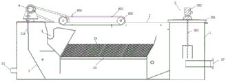
FIG. 1 is a schematic structural view of a high efficiency air-float water purification device according to the present invention;
FIG. 2 is a schematic view of a high efficiency air-floating water purification apparatus according to the present invention;
FIG. 3 is a schematic cross-sectional view of a high-efficiency air-floating water purification apparatus according to the present invention;
FIG. 4 is a schematic structural diagram of a stirring mechanism in a high-efficiency air-flotation water purification device according to the present invention;
FIG. 5 is a schematic structural diagram of a slag discharge mechanism in the high-efficiency air-flotation water purification device according to the present invention;
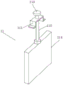
fig. 6 is a schematic structural view of a flow rate adjusting mechanism in a high-efficiency air-flotation water purifying device according to the present invention.
In the figure: 1. a treatment tank; 2. an air floatation tank; 3. a stirring mechanism; 301. a connecting plate; 302. a second drive motor; 303. a stirring rod; 4. a slag discharge groove; 5. a baffle plate; 6. a slag discharge mechanism; 601. a bearing fixing seat; 602. a transmission rod; 603. a conveyor belt; 604. a squeegee; 605. a driven gear; 7. a support plate; 8. a fixed block; 9. a first drive motor; 10. a driving gear; 11. a flow rate adjusting mechanism; 111. rotating the fixed frame; 112. a threaded rod; 113. a hand wheel; 114. an adjusting plate; 12. a first communication pipe; 13. a water pump; 14. a second communicating pipe; 15. an air compressor; 16. a pressure dissolved air tank; 17. a pressure reducing tube; 18. a pressure reducing valve; 19. a water inlet pipe; 20. a raw water pipe; 21. a clear water pipe; 22. a switch panel; 23. a partition plate; 24. an inclined tube; 25. a slag discharge pipe; 26. a sewage discharge pipe.
Detailed Description
The technical solutions in the embodiments of the present invention will be clearly and completely described below with reference to the drawings in the embodiments of the present invention, and it is obvious that the described embodiments are only a part of the embodiments of the present invention, and not all of the embodiments. All other embodiments, which can be derived by a person skilled in the art from the embodiments given herein without making any creative effort, shall fall within the protection scope of the present invention.
Example 1
Referring to fig. 1-6, the present invention provides the following technical solutions: a high-efficiency air-flotation water purification device comprises a treatment tank 1 and an air-flotation tank 2, wherein one side of the treatment tank 1 is fixedly connected with the air-flotation tank 2, the top end of the treatment tank 1 is fixedly connected with a stirring mechanism 3, one side of the air-flotation tank 2 is provided with a slag discharge groove 4, the bottom end of the air-flotation tank 2 is fixedly connected with a baffle 5 at one side of the slag discharge groove 4, the middle part of the top end of the baffle 5 is provided with a notch, the top end of the air-flotation tank 2 is fixedly connected with a slag discharge mechanism 6, one side of the top end of the air-flotation tank 2 is fixedly connected with a support plate 7, the back of the top end of the support plate 7 is fixedly connected with a fixed block 8, the top end of the fixed block 8 is fixedly connected with a first driving motor 9, an output shaft of the first driving motor 9 is fixedly connected with a driving gear, first communicating pipe 12 and water pump 13's the end intercommunication installation of intaking, water pump 13's play water end and second communicating pipe 14 intercommunication installation, second communicating pipe 14 still with 2 one side outer wall bottoms intercommunication installations in air supporting pond, it is provided with air compressor machine 15 to handle 1 one side in the pond, air compressor machine 15's gas outlet and pressure dissolve gas pitcher 16 intercommunication installation, pressure dissolve gas pitcher 16 bottom through decompression pipe 17 and 2 intercommunication installations in air supporting pond, relief pressure valve 18 is installed at decompression pipe 17 top, pressure dissolve gas pitcher 16 openly still the intercommunication and install inlet tube 19, 2 middle part fixedly connected with baffles 23 in air supporting pond, baffle 23 surface equidistance evenly alternates and is connected with a plurality of pipe chute 24, baffle 23 and 4 bottom fixed connection in scum groove, air supporting pond 2 is close to first driving motor 9 one side lateral wall fixedly connected.
In this embodiment: fixed connection that rabbling mechanism 3 includes is in the connecting plate 301 on 1 top in processing pond, and motor support fixedly connected with second driving motor 302 is passed through on connecting plate 301 top, and the output shaft of second driving motor 302 runs through connecting plate 301 and is located the inside stirring rod 303 fixed connection in processing pond 1, rotates through second driving motor 302 and drives stirring rod 303 and rotate, and then carries out intensive mixing to raw water and flocculating agent in handling pond 1, improves the flocculation effect.
In this embodiment: the deslagging mechanism 6 comprises four bearing fixing seats 601 fixedly connected to the top end of the air flotation tank 2, wherein a transmission rod 602 is rotatably connected between the two bearing fixing seats 601 on the same side, two transmission belts 603 are rotatably connected between the two transmission rods 602, scrapers 604 are fixedly connected to the top ends of one side and the bottom end of the other side of the two transmission belts 603, one end of the transmission rod 602 close to the first driving motor 9 is fixedly connected with a driven gear 605, the driven gear 605 is in transmission connection with a driving gear 10 through a chain, the driving gear 10 is driven to rotate through the rotation of the first driving motor 9, the driving gear 10 is connected with the driven gear 605 through the chain, and then the driven gear 605 drives the transmission rod 602 to rotate, the transmission rod 602 drives the transmission belt 603 to rotate, so that the scrapers 604 perform deslagging.
In this embodiment: flow control mechanism 11 includes fixed connection in the rotation mount 111 on backup pad 7 top, rotate mount 111 and threaded rod 112 threaded connection, threaded rod 112 top fixedly connected with hand wheel 113, the bearing frame that backup pad 7 and regulating plate 114 top fixed connection were run through to threaded rod 112 bottom rotates to be connected, regulating plate 114 and the sealed sliding connection of fluting, make threaded rod 112 drive regulating plate 114 go up and down in the fluting through rotatory hand wheel 113, make to have the space that purifies back clear water outflow between fluting and the regulating plate 114, and then adjust the velocity of flow of the clear water after purifying through the size in regulation space.
In this embodiment: the bottom end of the side wall of the treatment tank 1 is communicated with a raw water pipe 20, the bottom end of the side wall of the air flotation tank 2 opposite to the raw water pipe 20 is communicated with a clear water pipe 21, a worker injects raw water to be flocculated into the treatment tank 1 through the raw water pipe 20, and purified clear water is discharged through the clear water pipe 21.
In this embodiment: the deslagging pipe 25 is installed in the intercommunication of the front side wall of the air flotation tank 2, the deslagging pipe 25 is located at the bottom of the deslagging groove 4, the sewage discharge pipe 26 is installed in the intercommunication of the two sides of the bottom of the front side wall of the air flotation tank 2, the air floating body impurities collected in the deslagging groove 4 are removed through the deslagging pipe 25 by a worker, and the subsequent sewage purification caused by the excessive influence of the air floating body collection is avoided.
In this embodiment: the second driving motor 302, the first driving motor 9, the air compressor 15 and the water pump 13 are respectively electrically connected with the external power supply through a second driving motor control switch, a first driving motor control switch, an air compressor control switch and a water pump control switch on the switch panel 22, the switch panel 22 is electrically connected with the external power supply, and the electric equipment of the equipment is controlled through each control switch on the switch panel 22.
The working principle is as follows: the method comprises the steps that firstly, a worker injects sewage to be treated into a treatment tank 1 through a raw water pipe 20, then the air flotation tank 2 is filled with clear water, the worker injects water into a pressure dissolved air tank 16 through a water inlet pipe 19, then an air compressor control switch on a switch panel 22 is turned on, the air compressor 15 pressurizes the pressure dissolved air tank 16 to ensure that water in the pressure dissolved air tank 16 is fully mixed with gas compressed by the air compressor 15, then the worker injects a flocculating agent into the treatment tank 1 through a dosing device, then the worker turns on a second driving motor control switch on the switch panel 22, a second driving motor 302 starts to normally work, an output shaft of the second driving motor 302 drives a stirring rod 303 to start rotating to stir raw water and the flocculating agent in the treatment tank 1 at a high speed so that the flocculating agent is fully reacted with the flocculating agent to generate flocculate, then the worker turns on a water pump control switch on the switch panel 22, the water pump 13 pumps flocculated sewage generated in the treatment tank 1 into the air floatation tank 2 through the first communicating pipe 12 and the second communicating pipe 14, then the worker opens the pressure reducing valve 18, so that water dissolved with gas in the pressure dissolved gas tank 16 is injected into the air floatation tank 2 through the pressure reducing pipe 17 to generate a large amount of micro bubbles, the micro bubbles are adhered with flocculates to form an air floating body, the air floating body rises and floats to the surface of a water body according to the principle of buoyancy, then the worker opens the first driving motor control switch on the switch panel 22, the first driving motor 9 works to drive the driving gear 10 to rotate, the driving gear 10 is connected with the driven gear 605 through chain transmission, the driven gear 605 drives the transmission rod 602 to rotate, the transmission rod 602 is rotationally connected with the transmission belt 603, so that the transmission belt 603 drives the scraper 604 to scrape off impurities of the air floating body on the surface of the water, the scraped impurities enter the deslagging tank 4 to be collected, the air floatation area can be increased through the arranged inclined pipe 24, so that micro bubbles are prevented from being carried out under the turbulent flow state, a good laminar flow state is manufactured, the impurities with large specific gravity are better adhered to flocculates, the air floatation purification time is shortened, the air floatation purification efficiency is effectively improved, meanwhile, the impurities with large specific gravity sink to the bottom end of the air floatation tank 2 through the inclined pipe 24 to be precipitated through the inclined pipe 24, then a worker rotates the hand rotating wheel 113 to enable the threaded rod 112 to drive the adjusting plate 114 to ascend, a gap for purified clean water to flow out is reserved between the adjusting plate 114 and the open groove, the size of the gap is adjusted by adjusting the ascending height of the threaded rod 112, the flow rate of the purified clean water is controlled, and then the worker can remove the impurities with large specific gravity precipitated at the bottom end of the air floatation tank 2, the air floating body impurities collected in the slag discharge groove 4 are discharged through the slag discharge pipe 25, the phenomenon that the sewage purification efficiency is influenced due to excessive storage of the air floating body impurities is avoided, and clear water after air floating purification is discharged through the clear water pipe 21 for further treatment.
Finally, it should be noted that: although the present invention has been described in detail with reference to the foregoing embodiments, it will be apparent to those skilled in the art that changes may be made in the embodiments and/or equivalents thereof without departing from the spirit and scope of the invention. Any modification, equivalent replacement, or improvement made within the spirit and principle of the present invention should be included in the protection scope of the present invention.
Claims (7)
1. The utility model provides a high efficiency air supporting water purification unit, includes treatment tank (1) and air supporting pond (2), its characterized in that: the device is characterized in that an air floatation tank (2) is fixedly connected to one side of a treatment tank (1), a stirring mechanism (3) is fixedly connected to the top end of the treatment tank (1), a slag discharge groove (4) is formed in one side of the air floatation tank (2), a baffle (5) is fixedly connected to one side of the slag discharge groove (4) at the bottom end of the air floatation tank (2), a slot is formed in the middle of the top end of the baffle (5), a slag discharge mechanism (6) is fixedly connected to the top end of the air floatation tank (2), a support plate (7) is fixedly connected to one side of the top end of the air floatation tank (2), a fixed block (8) is fixedly connected to the back of the top end of the support plate (7), a first driving motor (9) is fixedly connected to the top end of the fixed block (8), an output shaft of the first driving motor, the utility model discloses a sealed sliding connection of fluting, including backup pad (7) top still fixedly connected with flow control mechanism (11), flow control mechanism (11) with the sealed sliding connection of fluting, handle pond (1) one side outer wall bottom intercommunication and install first communicating pipe (12), first communicating pipe (12) and the installation of the end intercommunication of intaking of water pump (13), the play water end and the installation of second communicating pipe (14) intercommunication of water pump (13), second communicating pipe (14) still with air supporting pond (2) one side outer wall bottom intercommunication installation, it is provided with air compressor machine (15) to handle pond (1) one side, the gas outlet and the pressure of air compressor machine (15) dissolve gas pitcher (16) intercommunication installation, pressure dissolve gas pitcher (16) bottom and install with air supporting pond (2) intercommunication through decompression pipe (17), relief pressure release valve (18) are installed at decompression pipe (17) top, inlet tube (19) are openly still installed in intercommunication to pressure dissolve gas pitcher (16), air supporting pond (2) middle part fixedly connected with baffle (23), baffle (23) surface equidistance evenly alternates and is connected with a plurality of pipe chute (24), baffle (23) and row's cinder notch (4) bottom fixed connection, air supporting pond (2) are close to first driving motor (9) one side lateral wall fixedly connected with flush mounting plate of switch (22).
2. The high-efficiency air-flotation water purifying device as claimed in claim 1, wherein: fixed connection that rabbling mechanism (3) include is in connecting plate (301) of handling pond (1) top, motor support fixedly connected with second driving motor (302) is passed through on connecting plate (301) top, the output shaft of second driving motor (302) runs through connecting plate (301) and is located the inside stirring rod (303) fixed connection of handling pond (1).
3. The high-efficiency air-flotation water purifying device as claimed in claim 1, wherein: the slag discharging mechanism (6) comprises four bearing fixing seats (601) fixedly connected to the top end of the air floatation tank (2), wherein the bearing fixing seats (601) are located on the same side, a transmission rod (602) is rotatably connected between the bearing fixing seats (601), two transmission rods (603) are rotatably connected between the two transmission rods (602), the top ends of one sides of the two transmission belts (603) and the bottom ends of the other sides of the two transmission belts are fixedly connected with scraping plates (604), one end of each transmission rod (602) close to the first driving motor (9) is fixedly connected with a driven gear (605), and the driven gear (605) is in transmission connection with a driving gear (10) through a chain.
4. The high-efficiency air-flotation water purifying device as claimed in claim 1, wherein: flow control mechanism (11) include rotation mount (111) of fixed connection in backup pad (7) top, rotate mount (111) and threaded rod (112) threaded connection, threaded rod (112) top fixedly connected with hand wheel (113), threaded rod (112) bottom is run through backup pad (7) and adjusting plate (114) top fixed connection's bearing frame and is rotated and be connected, adjusting plate (114) and the sealed sliding connection of fluting.
5. The high-efficiency air-flotation water purifying device as claimed in claim 1, wherein: a raw water pipe (20) is installed in the bottom end of the side wall of the treatment tank (1) in a communicated mode, and a clear water pipe (21) is installed just opposite to the bottom end of the side wall of the raw water pipe (20) in the air floatation tank (2) in a communicated mode.
6. The high-efficiency air-flotation water purifying device as claimed in claim 1, wherein: the air supporting pond (2) openly the lateral wall intercommunication install row's sediment pipe (25), row's sediment pipe (25) are located row's sediment groove (4) bottom, air supporting pond (2) openly lateral wall bottom both sides all communicate and install blow off pipe (26).
7. The high-efficiency air-flotation water purifying device as claimed in claim 2, wherein: the second driving motor (302), the first driving motor (9), the air compressor (15) and the water pump (13) are respectively electrically connected with an external power supply through a second driving motor control switch, a first driving motor control switch, an air compressor control switch and a water pump control switch on a switch panel (22), and the switch panel (22) is electrically connected with the external power supply.
Priority Applications (1)
| Application Number | Priority Date | Filing Date | Title |
|---|---|---|---|
| CN202110019019.0A CN112723604A (en) | 2021-01-07 | 2021-01-07 | High efficiency air supporting water purification unit |
Applications Claiming Priority (1)
| Application Number | Priority Date | Filing Date | Title |
|---|---|---|---|
| CN202110019019.0A CN112723604A (en) | 2021-01-07 | 2021-01-07 | High efficiency air supporting water purification unit |
Publications (1)
| Publication Number | Publication Date |
|---|---|
| CN112723604A true CN112723604A (en) | 2021-04-30 |
Family
ID=75591118
Family Applications (1)
| Application Number | Title | Priority Date | Filing Date |
|---|---|---|---|
| CN202110019019.0A Pending CN112723604A (en) | 2021-01-07 | 2021-01-07 | High efficiency air supporting water purification unit |
Country Status (1)
| Country | Link |
|---|---|
| CN (1) | CN112723604A (en) |
Cited By (1)
| Publication number | Priority date | Publication date | Assignee | Title |
|---|---|---|---|---|
| CN114772735A (en) * | 2022-03-17 | 2022-07-22 | 杭州国泰环保科技股份有限公司 | Floated ecological bed system that floats of multilayer aquatic plant |
Citations (3)
| Publication number | Priority date | Publication date | Assignee | Title |
|---|---|---|---|---|
| CN108194678A (en) * | 2017-12-28 | 2018-06-22 | 安徽荣达阀门有限公司 | A kind of flow control valve door gear |
| CN208829418U (en) * | 2018-06-12 | 2019-05-07 | 河北众源水处理设备有限公司 | A kind of sewage solid-liquid separation device |
| CN210367056U (en) * | 2019-07-05 | 2020-04-21 | 苏州清泉环保科技有限公司 | High-efficiency dissolved air floatation treatment equipment |
-
2021
- 2021-01-07 CN CN202110019019.0A patent/CN112723604A/en active Pending
Patent Citations (3)
| Publication number | Priority date | Publication date | Assignee | Title |
|---|---|---|---|---|
| CN108194678A (en) * | 2017-12-28 | 2018-06-22 | 安徽荣达阀门有限公司 | A kind of flow control valve door gear |
| CN208829418U (en) * | 2018-06-12 | 2019-05-07 | 河北众源水处理设备有限公司 | A kind of sewage solid-liquid separation device |
| CN210367056U (en) * | 2019-07-05 | 2020-04-21 | 苏州清泉环保科技有限公司 | High-efficiency dissolved air floatation treatment equipment |
Cited By (2)
| Publication number | Priority date | Publication date | Assignee | Title |
|---|---|---|---|---|
| CN114772735A (en) * | 2022-03-17 | 2022-07-22 | 杭州国泰环保科技股份有限公司 | Floated ecological bed system that floats of multilayer aquatic plant |
| CN114772735B (en) * | 2022-03-17 | 2023-05-09 | 杭州国泰环保科技股份有限公司 | Ecological bed system that floats of suspension type multilayer aquatic plant |
Similar Documents
| Publication | Publication Date | Title |
|---|---|---|
| CN113149280B (en) | High-efficient sewage treatment system | |
| CN112340804A (en) | Vertical flow type air flotation machine for wastewater treatment | |
| CN215886443U (en) | High-efficient air supporting water treatment facilities | |
| CN112723604A (en) | High efficiency air supporting water purification unit | |
| CN111498979B (en) | Ozone adding device used in sewage treatment process | |
| CN101575124B (en) | Rotary dissolving air flotation purifier | |
| CN210163246U (en) | High-efficient air supporting deposits integrative device | |
| CN213708002U (en) | Composite sewage treatment device | |
| CN213707994U (en) | Large-scale H that contains2Efficient S petrochemical sewage air floatation treatment system | |
| CN211546007U (en) | Novel cavitation air supporting device | |
| CN112250125A (en) | Scum separation system and water treatment equipment comprising same | |
| CN210595365U (en) | Integrated air floatation machine | |
| CN210825517U (en) | Gas dissolving system device for pressurized gas dissolving and air floating water treatment | |
| CN210656461U (en) | Dissolved air flotation water purifying device | |
| CN209853875U (en) | Integrated water purifying device | |
| CN211141581U (en) | Novel air supporting machine for sewage treatment | |
| CN213865417U (en) | Scum separation system and water treatment equipment comprising same | |
| CN215627276U (en) | A air supporting deposits all-in-one for sewage treatment | |
| CN219174306U (en) | Air-floatation coagulation separation device | |
| CN220665011U (en) | Sediment air supporting integrated device | |
| CN220684820U (en) | Efficient dissolved air floatation machine for sewage treatment | |
| CN220317462U (en) | Printing and dyeing sewage treatment air supporting pond | |
| CN210559774U (en) | Novel integral type air supporting waste water treatment equipment | |
| CN216863851U (en) | Ecological environmental protection quality of water clarification plant | |
| CN216191515U (en) | Dissolved air flotation machine |
Legal Events
| Date | Code | Title | Description |
|---|---|---|---|
| PB01 | Publication | ||
| PB01 | Publication | ||
| SE01 | Entry into force of request for substantive examination | ||
| SE01 | Entry into force of request for substantive examination | ||
| RJ01 | Rejection of invention patent application after publication | ||
| RJ01 | Rejection of invention patent application after publication |
Application publication date: 20210430 |