Improved suspension support frame for cleaning building outer wall glass
Technical Field
The invention relates to an improved suspension support frame for cleaning building outer wall glass.
Background
When the high-rise building outer wall glass needs to be cleaned, professional workers are specially hired to treat the outer wall glass, at present, the workers responsible for cleaning the building outer wall glass can directly tie lifting ropes on certain fixed supporting points of a parapet, and the operation mode has potential safety hazards.
Disclosure of Invention
In order to solve the problems, the invention provides an improved suspension support frame for cleaning building outer wall glass, which has the characteristics of novel structure, simplicity and convenience in disassembly and assembly, high safety performance and strong practicability.
In order to achieve the purpose, the invention adopts the following specific technical measures: an improved suspension support frame for cleaning building outer wall glass, which consists of a fixing mechanism and a hanger mechanism and is characterized in that,
the first steel pipes are bent to form n-shaped clamping pipes, the left first steel pipe and the right first steel pipe are pulled open in parallel, an upper transverse steel pipe and a lower transverse steel pipe are welded between the front sides of the left first steel pipe and the right first steel pipe, and an upper transverse steel pipe and a lower transverse steel pipe are welded between the rear sides of the left first steel pipe and the right first steel pipe;
a transverse connecting steel plate is welded between the middle parts of the front sides of the left first steel pipe and the right first steel pipe, and a left vertical through hole and a right vertical through hole are drilled in the transverse connecting steel plate;
the transverse steel plate, the transverse steel pipe I and the transverse steel pipe II are parallel to each other;
the first steel pipe, the transverse steel pipe I, the transverse steel pipe II and the transverse steel plate are combined to form a fixing mechanism;
the fixing mechanism can be clamped downwards from the top end of the parapet through the left first steel pipe and the right first steel pipe, so that the purpose of fastening and connecting the fixing mechanism and the parapet is achieved;
the second steel pipes are bent to form n-shaped hanger pipes, the left second steel pipes and the right second steel pipes are pulled open in parallel, a third transverse connecting steel pipe is welded between the upper ends of the front sides of the left second steel pipes and the right second steel pipes, and a fourth five transverse connecting steel pipes are welded between the rear sides of the left second steel pipes and the right second steel pipes;
the front pipe ends of the left second steel pipe and the right second steel pipe are milled with rotary connecting grains;
the left second steel pipe and the right second steel pipe can be embedded downwards from the upper part of the fixing mechanism;
the front pipe end of the second steel pipe on the left side can be downwards inserted into the vertical through hole on the left side in the transverse connecting steel plate and is screwed with a first positioning nut;
the front pipe end of the second steel pipe on the right side can be downwards inserted into the vertical through hole on the right side in the transverse connecting steel plate and is screwed with a second positioning nut;
the second steel pipe, the first positioning nut, the second positioning nut, the third transverse connecting steel pipe and the fourth transverse connecting steel pipe are combined to form the hanging frame mechanism.
Because the force generated when the building outer wall cleaning operation is carried out is vertical downward, the hanger mechanism and the fixing mechanism can be stably fixed on the parapet all the time, and the safety performance is higher during the operation.
The cross-connecting steel pipe IV can be used for binding a lifting rope and a safety rope respectively, and the invention can also effectively avoid the breakage caused by the friction between the lifting rope and the safety rope and the corner of the parapet wall.
The invention has the advantages of novel structure, simple and convenient disassembly and assembly, high safety performance and strong practicability.
The invention is further described below with reference to the accompanying drawings and examples.
Drawings
FIG. 1 is a side view of the composite joint structure of the present invention in an installed condition;
FIG. 2 is a side view of the composite connection structure of the present invention;
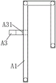
FIG. 3 is a side view of the fastening mechanism of the present invention;
FIG. 4 is a left side view of FIG. 3;
FIG. 5 is a side view of the combination coupling structure of the hanger mechanism of the present invention;
fig. 6 is a left side view of fig. 5.
In the figure: the steel pipe comprises a first steel pipe A1, a first transverse connecting steel pipe A2, a first transverse connecting steel plate A3, a vertical through hole A31, a second steel pipe B1, a third transverse connecting steel pipe B2, a fourth transverse connecting steel pipe B3, a first positioning nut B41, a second positioning nut B42 and a parapet wall C.
Detailed Description
As shown in fig. 1, fig. 2, fig. 3, fig. 4, fig. 5 and fig. 6, an improved suspension support frame for cleaning building outer wall glass is composed of a fixing mechanism and a hanging bracket mechanism, and is characterized in that,
the first steel pipe A1 is bent to form an n-shaped clamping pipe, the left first steel pipe A1 and the right first steel pipe A1 are pulled open in parallel, an upper transverse steel pipe A2 and a lower transverse steel pipe A2 are welded between the front sides of the left first steel pipe A1 and the right first steel pipe A1, and an upper transverse steel pipe B and a lower transverse steel pipe B are welded between the rear sides of the left first steel pipe A1 and the right first steel pipe A1;
a transverse connecting steel plate A3 is welded between the middle parts of the front sides of the left and right first steel pipes A1, and a left and right vertical through hole A31 is drilled on the transverse connecting steel plate A3;
the transverse steel plate A3, the transverse steel pipe A2 and the transverse steel pipe II are parallel to each other;
the first steel pipe A1, the first transverse connecting steel pipe A2, the second transverse connecting steel pipe and the transverse connecting steel plate A3 are combined to form a fixing mechanism;
the fixing mechanism can be clamped downwards from the top end of the parapet C through the left first steel pipe A1 and the right first steel pipe A1, so that the purpose of fastening and connecting the fixing mechanism and the parapet C is achieved;
the second steel pipes B1 are bent to form n-shaped hanger pipes, the left second steel pipe B1 and the right second steel pipe B1 are pulled open in parallel, a transverse steel pipe III B2 is welded between the upper ends of the front sides of the left second steel pipe B1 and the right second steel pipe B1, and five transverse steel pipes IV B3 are welded between the rear sides of the left second steel pipe B1 and the right second steel pipe B1;
the front pipe ends of the left second steel pipe B1 and the right second steel pipe B1 are milled with screw joint lines;
the left second steel pipe B1 and the right second steel pipe B1 can be embedded downwards from the upper part of the fixing mechanism;
the front pipe end of the second steel pipe B1 positioned on the left side can be downwards inserted into the vertical through hole positioned on the left side in the transverse steel plate A3 and is screwed with a first positioning nut B41;
the front pipe end of the second steel pipe B1 positioned on the right side can be downwards inserted into the vertical through hole positioned on the right side in the transverse steel plate A3 and is screwed with a second positioning nut B42;
the second steel pipe B1, the first positioning nut B41, the second positioning nut B42, the third transverse steel pipe B2 and the fourth transverse steel pipe B3 are combined to form a hanger mechanism.