Automotive interior spare forming die with heating function
Technical Field
The invention relates to the technical field of molds, in particular to a forming mold for an automotive interior part with a heating function.
Background
The automotive interior part has the functions of decorating and beautifying the automobile, the internal and external images of the automobile are directly influenced by the quality of the decorative effect, the decorative part is pertinently selected according to the actual condition of the automobile according to the principles of beauty, coordination, practicability and safety, the decorative effect is ensured, the automotive interior part is finished through a forming die, and the appearance of an article is processed mainly through the change of the physical state of a formed material. Plain has the title of "industrial mother"; aiming at some dies for molding raw materials by extrusion, in the production and processing process, because the dies do not have the heating function, cracks often appear in the extrusion process of the raw materials, which leads to the appearance of inferior-quality products, the existing forming die with the heating function is provided, and the defects can be effectively solved;
through retrieval, in a patent of a forming die with a heating function disclosed in application number CN201921073159.0, an electric heating tube is arranged in a second cavity surrounded by a fixed block and an upper die, so that the raw material can be heated in the process of processing and forming the raw material, the efficiency and the success rate of forming the raw material are improved, and the upper die can be detached from the fixed block by detaching a fastening screw, so that the electric heating tube is convenient to replace;
the following drawbacks remain for the above patents: although the heating function of the raw material can be realized by arranging the heating pipe, and the detachment of the heating pipe is realized by the matching of the fastening screw and the thread, when the heating pipe is detached, the operation can be completed by using an external tool, and when the heating pipe is installed, the installation block between the fixed block and the upper die needs to be repeatedly butted, so that the two installation holes are positioned on the same straight line, at the moment, the fastening screw is inserted into the installation hole, and the fastening screw is rotationally locked by the external tool, and the installation of the heating pipe is completed, the operation process is complicated, time and labor are consumed, the quick detachment of the heating pipe is realized on the premise that the external tool is not provided, the detachment process of the heating pipe is delayed, the detachment efficiency is reduced, and the fastening screw is repeatedly screwed, so that the surface of the fastening screw repeatedly rubs with the thread, make the screw thread wearing and tearing appear, lead to fastening screw and screw thread to mismatch for the fixed block with go up the mould installation unstability, lead to the mould to take place to rock at the in-process of work again, further cause the influence to the processingquality of work piece, increased the probability that the wastrel produced, and then reduced work efficiency, reduced the practicality.
Disclosure of Invention
According to the technical problems, the invention provides an automobile interior trim part forming die with a heating function, which is characterized by comprising a top plate, an upper die, a fixed plate, a supporting cylinder, a mounting plate, a spring, a supporting plate, a push rod, a push plate, a limiting plate, a pull ring, a protective pad, a lower die, a bottom plate and a telescopic rod, wherein one end of the telescopic rod is arranged at each of the left end and the right end of the bottom plate; the bottom of the upper die is provided with a fixed plate, the left side wall and the right side wall of the upper die are respectively provided with a sliding chute, two ends of the fixed plate are respectively matched with the sliding chutes for use, the left end and the right end of the upper die are respectively provided with a rectangular groove, the rectangular grooves are arranged on the upper sides of the sliding chutes, one end of each rectangular groove is provided with a supporting cylinder, and the other end of each rectangular groove is provided with a rectangular through hole; one end of a mounting plate is arranged in the supporting cylinder, one end of a spring is mounted at the other end of the mounting plate, one end of a supporting plate is mounted at the other end of the spring, one end of a push rod is mounted at the other end of the supporting plate, the other end of the push rod penetrates through the rectangular through hole to extend to the outer side of the upper die and is provided with a pull ring, a protective pad is arranged on the outer side wall of the pull ring, and the protective pad is made of rubber; a push plate is sleeved on the outer side wall of the pull rod, and a limiting plate is arranged at the bottom of the push plate; the bottom of the rectangular groove is provided with a through groove; the left end and the right end of the fixed plate are respectively provided with a slot, the side wall of each slot is provided with a limiting groove, the lower end of the push plate penetrates through the through groove and extends into the slots, and the limiting plate is matched with the limiting grooves for use; the sliding grooves are formed in the two ends of the fixing plate respectively and communicated with the rear ends of the slots, and transverse grooves are formed in the side walls of the sliding grooves.
The invention has the beneficial effects that: the invention adds a supporting cylinder, a mounting plate, a spring, a supporting plate, a push rod, a push plate, a limiting plate and a pull ring, drives the supporting plate to transversely move in the supporting cylinder by transversely pulling the pull rod, drives the spring in the supporting cylinder to generate spring deformation, drives the push plate to transversely move in the slot by the elastic action of the spring, further drives the limiting plate to transversely move, realizes the operation of matching or separating the limiting plate and the limiting plate, achieves the aim of locking and releasing the fixing plate by the limiting block, realizes the disassembly and assembly of the fixing plate, thereby achieving the disassembly and replacement of a heating pipe, and through improvement, the disassembly and assembly of the fixing plate can be realized only by hand in the disassembly and assembly process without the help of external tools, further quickens the disassembly and assembly progress, does not need to repeatedly butt joint mounting holes when the fixing plate is installed, and reduces the operation steps to a certain, the process is simple to operate, time-saving and labor-saving, and avoids the phenomena that the upper die shakes in the working process and a large number of defective products are generated in the production process due to the fact that the fixed plate is abraded in the dismounting process, and the like, so that the working efficiency of the invention is improved, and the practicability is improved;
the fixing plate is disassembled by arranging the sliding groove communicated with the slot, and when the limiting plate is separated from the limiting groove and the push plate and the limiting plate are moved to be on the same straight line with the sliding groove by pulling the pull rod, the fixing plate is manually pulled outwards to enable the sliding groove to move towards the front side of the upper die, so that the sliding groove penetrates through the push plate, the transverse groove penetrates through the limiting plate, and if the fixing plate in the moving process is separated from the upper die, the fixing plate is disassembled;
according to the invention, the protective pad is additionally arranged on the outer side wall of the pull ring, the protective pad made of rubber can play an effective protective role, and the use comfort level of the pull ring is further increased.
Drawings
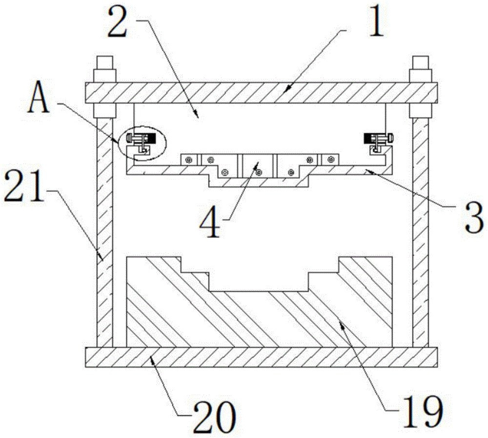
FIG. 1 is a schematic view of the overall structure of the present invention;
FIG. 2 is an enlarged view of the present invention at A;
FIG. 3 is a schematic view of the fixing plate of the present invention having slots and sliding grooves;
FIG. 4 is a schematic view of the side wall of the sliding groove provided with a transverse groove;
FIG. 5 is a schematic view of the fixing plate of the present invention in a disassembled state;
fig. 6 is a schematic view of the mounting of the pulling plate and the fixing plate according to the present invention.
As shown in the figure, 1-top plate, 2-upper die, 3-fixing plate, 4-heating component, 5-rectangular groove, 6-supporting cylinder, 7-mounting plate, 8-spring, 9-supporting plate, 10-push rod, 11-push plate, 12-limiting plate, 13-pull ring, 14-protecting pad, 15-slot, 16-limiting groove, 17-sliding groove, 18-transverse groove, 19-lower die, 20-bottom plate and 21-telescopic rod.
Detailed Description
Example 1
The invention provides a forming die for automotive interior parts with a heating function, which is characterized by comprising a top plate 1, an upper die 2, a fixed plate 3, a supporting cylinder 6, a mounting plate 7, a spring 8, a supporting plate 9, a push rod 10, a push plate 11, a limiting plate 12, a pull ring 13, a protective pad 14, a lower die 19, a bottom plate 20 and a telescopic rod 21, wherein the left end and the right end of the bottom plate 20 are respectively provided with one end of the telescopic rod 21, the other end of the telescopic rod 21 is provided with the top plate 1, the bottom of the top plate 1 is provided with the upper die 2, the bottom of the upper die 2 is provided with a groove, a heating component 4 is; the bottom of the upper die 2 is provided with a fixed plate 3, the left side wall and the right side wall of the upper die 2 are respectively provided with a sliding chute, two ends of the fixed plate 3 are respectively matched with the sliding chutes for use, the left end and the right end of the upper die 2 are respectively provided with a rectangular groove 5, the rectangular grooves 5 are arranged on the upper sides of the sliding chutes, one end of each rectangular groove 5 is provided with a supporting cylinder 6, and the other end of each rectangular groove 5 is provided with; one end of a mounting plate 7 is arranged in the supporting cylinder 6, one end of a spring 8 is arranged at the other end of the mounting plate 7, one end of a supporting plate 9 is arranged at the other end of the spring 8, one end of a push rod 10 is arranged at the other end of the supporting plate 9, the other end of the push rod 10 penetrates through the rectangular through hole to extend to the outer side of the upper die 2, a pull ring 13 is arranged, a protective pad 14 is arranged on the outer side wall of the pull ring 13, and the protective pad 14; a push plate 11 is sleeved on the outer side wall of the pull rod, and a limit plate 12 is arranged at the bottom of the push plate 11; the bottom of the rectangular groove 5 is provided with a through groove; the left end and the right end of the fixed plate 3 are respectively provided with a slot 15, the side wall of the slot 15 is provided with a limit groove 16, the lower end of the push plate 11 passes through the through groove and extends into the slot 15, and the limit plate 12 is matched with the limit groove 16 for use; the two ends of the fixing plate 3 are respectively provided with a sliding groove 17, the sliding groove 17 is communicated with the rear end of the slot 15, and the side wall of the sliding groove 17 is provided with a transverse groove 18.
Example 2
When the automobile interior trim part forming device is used, the heating component 4 is the prior art and is used for heating raw materials for forming the automobile interior trim part forming device, when the heating component 4 is used for a long time and is low in heating efficiency and needs to be disassembled and replaced, the pull ring 13 is held by a hand of a worker, the rubber protective pad 14 can play an effective protective role, the use comfort level of the pull ring 13 is further increased, the pull ring and the support plate 9 are pulled to the outer side of the upper die 2 to move outwards, the spring 8 is elastically deformed, the pull plate can be driven to move outwards, the limit plate 12 is further driven to be separated from the limit groove 16, the locking of the fixing plate 3 is released, the push plate 11 moves to be on the same straight line with the slide groove 17, the fixing plate 3 is pulled outwards manually, the slide groove 17 moves towards the front side of the upper die 2, and the slide groove 17 passes through the push plate 11, limiting plate 12 is passed to transverse groove 18, remove fixed plate 3 and last mould 2 in-process and take place the separation, the dismantlement of fixed plate 3 has been realized promptly, further can dismantle heating element 4, heating element 4 with its renewal, make push pedal 11 be in and slide groove 17 on same straight line through the pulling pull rod, insert fixed plate 3 in the spout at last mould 2 both ends, further will slide groove 17 and remove to the outside of push pedal 11, and continue to remove, make push pedal 11, limiting plate 12 is in slot 15, loosen the pull rod, make the railing move to rectangular channel 5 inside under the effect of spring 8 elasticity, make the stopper kick-back to spacing groove 16 in, further realize effective spacing to fixed plate 3, accomplish the installation of fixed plate 3 promptly.
The foregoing shows and describes the general principles and broad features of the present invention and advantages thereof. While the invention has been described with respect to the above embodiments, it will be understood by those skilled in the art that the invention is not limited to the above embodiments, which are described in the specification and illustrated only to illustrate the principles of the invention, but that various changes and modifications may be made without departing from the spirit and scope of the invention as defined by the appended claims. The scope of the invention is defined by the appended claims and equivalents thereof.