CN112704522A - Sampling device and sampling method for uterine cavity inner wall for gynecology - Google Patents
Sampling device and sampling method for uterine cavity inner wall for gynecology Download PDFInfo
- Publication number
- CN112704522A CN112704522A CN202011401838.3A CN202011401838A CN112704522A CN 112704522 A CN112704522 A CN 112704522A CN 202011401838 A CN202011401838 A CN 202011401838A CN 112704522 A CN112704522 A CN 112704522A
- Authority
- CN
- China
- Prior art keywords
- sampling
- wall
- uterine cavity
- pipe
- sample
- Prior art date
- Legal status (The legal status is an assumption and is not a legal conclusion. Google has not performed a legal analysis and makes no representation as to the accuracy of the status listed.)
- Granted
Links
- 238000005070 sampling Methods 0.000 title claims abstract description 138
- 238000000034 method Methods 0.000 title abstract description 10
- 230000007246 mechanism Effects 0.000 claims abstract description 55
- 238000004140 cleaning Methods 0.000 claims abstract description 23
- 238000003780 insertion Methods 0.000 claims abstract description 14
- 230000037431 insertion Effects 0.000 claims abstract description 14
- 238000005406 washing Methods 0.000 claims abstract description 6
- 239000007788 liquid Substances 0.000 claims description 51
- 230000005540 biological transmission Effects 0.000 claims description 8
- 239000007769 metal material Substances 0.000 claims description 4
- 230000008878 coupling Effects 0.000 claims description 3
- 238000010168 coupling process Methods 0.000 claims description 3
- 238000005859 coupling reaction Methods 0.000 claims description 3
- 210000001215 vagina Anatomy 0.000 description 6
- 238000010586 diagram Methods 0.000 description 4
- 230000009471 action Effects 0.000 description 3
- 238000001574 biopsy Methods 0.000 description 2
- 230000006378 damage Effects 0.000 description 2
- 244000005700 microbiome Species 0.000 description 2
- 230000008569 process Effects 0.000 description 2
- 230000007306 turnover Effects 0.000 description 2
- 208000027418 Wounds and injury Diseases 0.000 description 1
- 230000006978 adaptation Effects 0.000 description 1
- 230000004075 alteration Effects 0.000 description 1
- 230000009286 beneficial effect Effects 0.000 description 1
- 239000011248 coating agent Substances 0.000 description 1
- 238000000576 coating method Methods 0.000 description 1
- 238000003745 diagnosis Methods 0.000 description 1
- 201000010099 disease Diseases 0.000 description 1
- 208000037265 diseases, disorders, signs and symptoms Diseases 0.000 description 1
- 238000006073 displacement reaction Methods 0.000 description 1
- 210000004696 endometrium Anatomy 0.000 description 1
- 238000005516 engineering process Methods 0.000 description 1
- 230000002349 favourable effect Effects 0.000 description 1
- 238000011010 flushing procedure Methods 0.000 description 1
- 208000014674 injury Diseases 0.000 description 1
- 239000010687 lubricating oil Substances 0.000 description 1
- 230000004048 modification Effects 0.000 description 1
- 238000012986 modification Methods 0.000 description 1
- 238000010926 purge Methods 0.000 description 1
- 238000006467 substitution reaction Methods 0.000 description 1
- 230000001360 synchronised effect Effects 0.000 description 1
Images



Classifications
-
- A—HUMAN NECESSITIES
- A61—MEDICAL OR VETERINARY SCIENCE; HYGIENE
- A61B—DIAGNOSIS; SURGERY; IDENTIFICATION
- A61B10/00—Instruments for taking body samples for diagnostic purposes; Other methods or instruments for diagnosis, e.g. for vaccination diagnosis, sex determination or ovulation-period determination; Throat striking implements
- A61B10/02—Instruments for taking cell samples or for biopsy
- A61B10/0291—Instruments for taking cell samples or for biopsy for uterus
-
- A—HUMAN NECESSITIES
- A61—MEDICAL OR VETERINARY SCIENCE; HYGIENE
- A61B—DIAGNOSIS; SURGERY; IDENTIFICATION
- A61B1/00—Instruments for performing medical examinations of the interior of cavities or tubes of the body by visual or photographical inspection, e.g. endoscopes; Illuminating arrangements therefor
- A61B1/04—Instruments for performing medical examinations of the interior of cavities or tubes of the body by visual or photographical inspection, e.g. endoscopes; Illuminating arrangements therefor combined with photographic or television appliances
-
- A—HUMAN NECESSITIES
- A61—MEDICAL OR VETERINARY SCIENCE; HYGIENE
- A61B—DIAGNOSIS; SURGERY; IDENTIFICATION
- A61B1/00—Instruments for performing medical examinations of the interior of cavities or tubes of the body by visual or photographical inspection, e.g. endoscopes; Illuminating arrangements therefor
- A61B1/303—Instruments for performing medical examinations of the interior of cavities or tubes of the body by visual or photographical inspection, e.g. endoscopes; Illuminating arrangements therefor for the vagina, i.e. vaginoscopes
-
- A—HUMAN NECESSITIES
- A61—MEDICAL OR VETERINARY SCIENCE; HYGIENE
- A61M—DEVICES FOR INTRODUCING MEDIA INTO, OR ONTO, THE BODY; DEVICES FOR TRANSDUCING BODY MEDIA OR FOR TAKING MEDIA FROM THE BODY; DEVICES FOR PRODUCING OR ENDING SLEEP OR STUPOR
- A61M3/00—Medical syringes, e.g. enemata; Irrigators
- A61M3/02—Enemata; Irrigators
- A61M3/0279—Cannula; Nozzles; Tips; their connection means
-
- A—HUMAN NECESSITIES
- A61—MEDICAL OR VETERINARY SCIENCE; HYGIENE
- A61B—DIAGNOSIS; SURGERY; IDENTIFICATION
- A61B10/00—Instruments for taking body samples for diagnostic purposes; Other methods or instruments for diagnosis, e.g. for vaccination diagnosis, sex determination or ovulation-period determination; Throat striking implements
- A61B10/02—Instruments for taking cell samples or for biopsy
- A61B2010/0225—Instruments for taking cell samples or for biopsy for taking multiple samples
-
- A—HUMAN NECESSITIES
- A61—MEDICAL OR VETERINARY SCIENCE; HYGIENE
- A61M—DEVICES FOR INTRODUCING MEDIA INTO, OR ONTO, THE BODY; DEVICES FOR TRANSDUCING BODY MEDIA OR FOR TAKING MEDIA FROM THE BODY; DEVICES FOR PRODUCING OR ENDING SLEEP OR STUPOR
- A61M2210/00—Anatomical parts of the body
- A61M2210/14—Female reproductive, genital organs
- A61M2210/1433—Uterus
Landscapes
- Health & Medical Sciences (AREA)
- Life Sciences & Earth Sciences (AREA)
- Surgery (AREA)
- Engineering & Computer Science (AREA)
- Animal Behavior & Ethology (AREA)
- Veterinary Medicine (AREA)
- Biomedical Technology (AREA)
- Heart & Thoracic Surgery (AREA)
- Public Health (AREA)
- General Health & Medical Sciences (AREA)
- Medical Informatics (AREA)
- Molecular Biology (AREA)
- Pathology (AREA)
- Gynecology & Obstetrics (AREA)
- Reproductive Health (AREA)
- Physics & Mathematics (AREA)
- Biophysics (AREA)
- Nuclear Medicine, Radiotherapy & Molecular Imaging (AREA)
- Optics & Photonics (AREA)
- Radiology & Medical Imaging (AREA)
- Anesthesiology (AREA)
- Hematology (AREA)
- Ultra Sonic Daignosis Equipment (AREA)
Abstract
The invention discloses a sampling device and a sampling method for the inner wall of a uterine cavity for gynecology, which comprises the following steps: the sampling device comprises a sampling cylinder, a sampling mechanism and a cleaning mechanism, wherein an embedding mechanism is arranged in the sampling cylinder, and a sampling mechanism is arranged in the embedding mechanism and is connected with the cleaning mechanism; the mechanism of putting into is used for getting into the palace chamber, sampling mechanism is used for the sampling of palace intracavity wall, wiper mechanism is used for washing palace intracavity wall, the mechanism of putting into includes: the sampling device comprises a guide rod, a sliding block, an insertion tube, a gear, a rack, a buffer spring, a case and an insertion motor, wherein the sliding block is sleeved on the guide rod at equal intervals, the buffer spring is sleeved on one side of the sliding block, and the bottom of the sliding block is fixedly connected with the arc-shaped side wall at the top of the insertion tube.
Description
Technical Field
The invention relates to the technical field of medical instruments, in particular to a sampling device and a sampling method for the inner wall of a uterine cavity for gynecology.
Background
The sampling and biopsy of uterine cavity is the main basis for the accurate diagnosis of gynecological diseases, at present, in the gynecology of hospital, uterine curettage is generally adopted to obtain endometrium for biopsy, namely, a uterine cavity dilator is used to dilate uterine orifice, a hand-held instrument is used to stretch into the uterine cavity, and a specimen is scraped on the inner wall of the uterine cavity.
However, the existing uterine cavity inner wall sampling device has the following disadvantages: (1) female patients suffer severe pain and are cumbersome to operate; (2) a plurality of samples cannot be collected at one time during sampling; (3) the condition of the inner wall of the uterine cavity cannot be seen during sampling; (4) the sample is contaminated with vaginal microorganisms upon withdrawal.
Disclosure of Invention
The invention aims to provide a gynecological uterine cavity inner wall sampling device and a gynecological uterine cavity inner wall sampling method, and aims to solve the problems in the background technology.
In order to achieve the purpose, the invention provides the following technical scheme: a sampling device and a sampling method for the internal wall of a uterine cavity for gynecology comprise: the sampling device comprises a sampling cylinder, a sampling mechanism and a cleaning mechanism, wherein an embedding mechanism is arranged in the sampling cylinder, and a sampling mechanism is arranged in the embedding mechanism and is connected with the cleaning mechanism;
the embedding mechanism is used for entering the uterine cavity, the sampling mechanism is used for sampling the inner wall of the uterine cavity, and the cleaning mechanism is used for washing the inner wall of the uterine cavity.
Further, the insertion mechanism includes: guide arm, slider, imbed pipe, gear, rack, buffer spring, quick-witted case, put into the motor, the slider equidistance cup joint in on the guide arm, buffer spring cup joint in one side of slider, the bottom of slider with the arc lateral wall fixed connection at the top of imbedding the pipe, the rack set up in the bottom arc lateral wall of imbedding the pipe, the gear with the rack meshing meets, it install in to imbed the motor the quick-witted incasement, the output shaft of imbedding the motor with gear drive connects.
Further, put into the pipe set up in the sampling tube, the both ends fixed mounting of guide arm in the inner wall at sampling tube both ends, the gear set up in the bottom of sampling tube, the axle center of gear is connected with the pivot, the both ends of pivot install in the inner wall of sampling tube, the one end of pivot is passed the inner wall of sampling tube with the output shaft of putting into the motor passes through the shaft coupling transmission and is connected, quick-witted case install in the outer wall of sampling tube.
Further, the sampling mechanism comprises: inner chamber, sample motor, screw rod, sliding sleeve, camera, sample ring, sample groove, spout, slide bar, the sample motor install in the inner chamber, the output shaft of sample motor with screw rod transmission connects, sliding sleeve threaded connection in on the screw rod, the sample ring with the other end threaded connection of sliding sleeve, the sample groove evenly seted up in on the sample ring, the camera install in be located on the sliding sleeve the both sides of sample ring, the spout is seted up in the top of inner chamber, slide bar sliding connection in the spout.
Further, the inner cavity is arranged in the imbedding pipe, a threaded hole is formed in one end of the sliding sleeve, a connecting rod is fixed at one end of the sampling ring, the connecting rod is in threaded connection with the threaded hole, and an opening is formed in one end of the imbedding pipe.
Further, the cleaning mechanism includes: the liquid storage device comprises a push rod, a push plate, a liquid storage cylinder, a liquid discharge pipe and a liquid inlet pipe, wherein the push rod is fixedly connected with the push plate, the push plate is arranged in the liquid storage cylinder, one end of the liquid discharge pipe is communicated with the inside of the liquid storage cylinder, the other end of the liquid discharge pipe extends out of an opening of an embedded pipe, and one end of the liquid inlet pipe is communicated with the liquid storage cylinder.
Furthermore, the push rod is arranged in the imbedding pipe in a zigzag mode, the size of the push plate is matched with the size of the inner wall of the liquid storage cylinder, the liquid discharge pipe is L-shaped, the imbedding pipe is located a through groove is formed in the bottom of the inner cavity, and one end of the push rod penetrates through the through groove and is fixedly connected with the sliding sleeve.
Further, the outer wall of sampler barrel has seted up the window, the window articulates there is the window door.
Furthermore, the sampling ring is arranged in parallel to the ground and is made of elastic metal materials.
Furthermore, one-way valves are arranged in the liquid inlet pipe and the liquid outlet pipe.
Compared with the prior art, the invention has the beneficial effects that:
(1) according to the invention, the embedding mechanism is arranged, the gear is driven to rotate by the embedding motor, the gear is meshed and connected with the rack at the bottom of the embedding tube, the embedding tube is pushed by the gear to move to the uterine cavity through the vagina, the sampling mechanism is driven by the embedding tube to move to the uterine cavity, the slider connected to the top of the embedding tube moves on the guide rod to limit, so that the embedding tube moves stably, and the embedding tube is more gentle when entering the uterine cavity by extruding the buffer spring through the slider;
(2) the sampling mechanism is arranged, the sliding sleeve is embedded and installed in the sliding groove through the sliding rod to achieve limiting through rotation of the sampling motor, the sliding sleeve is further enabled to move on the screw rod, the sampling ring is pushed out of the opening formed in the inserting tube through movement of the screw rod, the sampling ring is made of elastic metal materials and can stretch out after extending out of the opening formed in the inserting tube, the sampling cylinder is slightly rotated, the sampling groove formed in the side wall of the sampling ring samples the inner wall of the uterine cavity, multiple samples are taken out at one time, the sampling ring is retracted into the inserting tube through overturning of the sampling motor, and the inserting tube is prevented from being polluted when exiting from the vagina;
(3) according to the invention, the cleaning mechanism is arranged, so that the push rod is driven to move in the sliding groove when the sliding sleeve retreats on the screw rod, the push plate is further used for extruding the cleaning liquid in the liquid storage cylinder, the cleaning liquid is extruded out of the liquid discharge pipe from the liquid storage cylinder, and when the sampling ring finishes sampling and is retracted into the pipe, the uterine cavity is washed through the liquid discharge pipe;
(4) when the invention is sent into the uterine cavity from the vagina through the inserting tube, the sampling mechanism is sent into the uterine cavity, a plurality of sampling grooves are arranged through the sampling ring, thereby realizing a plurality of samplings, avoiding the pain of putting and sampling through expanding the uterine cavity, and also needing no frequent operation for a plurality of times, the sampling ring is connected with the threaded hole of the inserting tube through the connecting rod in a threaded manner, thereby being convenient to replace, leading the sampling ring to be disposable and more clean and sanitary, leading a doctor to keep a certain distance during sampling through the sampling cylinder with a certain length, observing the inner wall of the uterine cavity through the camera, further checking the inserting depth of the inserting tube and the condition of the inner wall of the uterine cavity, and the invention can automatically sample, collect a plurality of samples at one time, facilitate the flushing of the uterine cavity after the sampling is finished, avoiding the samples from being polluted by microorganisms in the vagina, and needing not to expand the uterine cavity, the more comfortable sampling device for the inner wall of the uterine cavity is placed without using a dilator.
Drawings
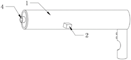
FIG. 1 is a schematic diagram of a front view of an internal structure according to an embodiment of the present invention;
FIG. 2 is a schematic structural diagram of a front view of the embodiment of FIG. 1;
FIG. 3 is a schematic structural diagram of another side of the front view of the embodiment of FIG. 1;
FIG. 4 is a schematic structural view of the insertion mechanism in the embodiment of FIG. 1;
FIG. 5 is a schematic structural view of the sampling mechanism and the purge mechanism in the embodiment of FIG. 1;
FIG. 6 is a schematic structural view of the sampling mechanism in the embodiment of FIG. 1;
fig. 7 is a schematic structural diagram of the sampling ring in the embodiment of fig. 1.
Reference numerals: 1. a sampling tube; 2. a placement mechanism; 21. a guide bar; 22. a slider; 23. placing the tube in; 24. a gear; 25. a rack; 26. a buffer spring; 27. a chassis; 28. placing a motor; 3. a sampling mechanism; 31. an inner cavity; 32. a sampling motor; 33. a screw; 34. a sliding sleeve; 341. a threaded hole; 35. a camera; 36. a sampling ring; 361. a connecting rod; 37. a sampling groove; 38. a chute; 39. a slide bar; 4. a cleaning mechanism; 41. a push rod; 42. pushing the plate; 43. a liquid storage cylinder; 44. a liquid discharge pipe; 45. a liquid inlet pipe; 5. and (4) a window.
Detailed Description
The technical solutions in the embodiments of the present invention will be clearly and completely described below with reference to the drawings in the embodiments of the present invention, and it is obvious that the described embodiments are only a part of the embodiments of the present invention, and not all of the embodiments. All other embodiments, which can be derived by a person skilled in the art from the embodiments given herein without making any creative effort, shall fall within the protection scope of the present invention.
Referring to fig. 1-7, a sampling device for uterine cavity inner wall in gynecology comprises: the sampling device comprises a sampling cylinder 1, wherein an embedding mechanism 2 is arranged in the sampling cylinder 1, a sampling mechanism 3 is arranged in the embedding mechanism 2, and the sampling mechanism 3 is connected with a cleaning mechanism 4;
the embedding mechanism 2 is used for entering the uterine cavity, the sampling mechanism 3 is used for sampling the inner wall of the uterine cavity, and the cleaning mechanism 4 is used for washing the inner wall of the uterine cavity.
The insertion mechanism 2 includes: guide rod 21, slider 22, put into pipe 23, gear 24, rack 25, buffer spring 26, quick-witted case 27, put into motor 28, slider 22 equidistance cup joints in on the guide rod 21, the equidistance sets up slider 22 is favorable to putting into pipe 23 adjustment and gets into the distance of affected part and equals, avoids getting into the affected part too deeply, leads to the secondary damage, buffer spring 26 cup joints in one side of slider 22, the bottom of slider 22 with put into the arc lateral wall fixed connection at the top of pipe 23, rack 25 set up in put into the bottom arc lateral wall of pipe 23, gear 24 with rack 25 meshing meets, put into motor 28 and install in quick-witted case 27, put into motor 28 the output shaft with gear 24 transmission is connected, rotates through putting into motor 28 and drives gear 24 and rotates, gear 24 meets with the rack 25 meshing of putting into pipe 23 bottom, and then promote through gear 24 and put into pipe 23 and remove to the palace chamber through the vagina, can drive sampling mechanism 3 synchronous movement through putting into pipe 23 and removing, wherein, control the rotation of gear drives the displacement distance of rack 25, and then the distance that the control got into the affected part avoids carrying out the secondary injury to the affected part.
Put into pipe 23 set up in the sampling tube 1, the both ends fixed mounting of guide arm 21 in the inner wall at 1 both ends of sampling tube, gear 24 set up in the bottom of sampling tube 1, the axle center of gear 24 is connected with the pivot, and the pivot is rotated and is driven gear 24 and rotate, the both ends of pivot install in the inner wall of sampling tube 1, the one end of pivot is passed the inner wall of sampling tube 1 with the output shaft of putting into motor 28 passes through the shaft coupling transmission and connects, quick-witted case 27 install in the outer wall of sampling tube 1, the handle is installed to the one end bottom of sampling tube 1, installs two control switch on the handle, and control switch is respectively through the wire and put into motor 28 and sampling motor 32 electric connection.
The sampling mechanism 3 includes: inner chamber 31, sample motor 32, screw rod 33, sliding sleeve 34, camera 35, sample ring 36, sample groove 37, spout 38, slide bar 39, sample motor 32 install in the inner chamber 31, the output shaft of sample motor 32 with screw rod 33 transmission is connected, sliding sleeve 34 threaded connection in on the screw rod 33, sample ring 36 with the other end threaded connection of sliding sleeve 34, sample groove 37 evenly sets up on sample ring 36, camera 35 install in lie in on sliding sleeve 34 the both sides of sample ring 36, spout 38 sets up in the top of inner chamber 31, slide bar 39 sliding connection in spout 38, sample motor 32 drive screw rod 33 rotates, makes sliding sleeve 34 remove along spout 38 on screw rod 33, makes sample ring 36 enter into the palace intracavity through the opening of putting into pipe 23 to stretch and open, and take a sample to palace intracavity wall through sample groove 37 of sample ring 36, the sampling ring 36 may be provided in any shape suitable for the interior of the uterine cavity, such as oval, pyramidal circular, etc.
The inner cavity 31 is arranged in the inserting tube 23, a threaded hole 341 is formed in one end of the sliding sleeve 34, a connecting rod 361 is fixed to one end of the sampling ring 36, the connecting rod 361 is in threaded connection with the threaded hole 341, an opening is formed in one end of the inserting tube 23, and the sampling ring 36 is convenient to detach.
The cleaning mechanism 4 includes: push rod 41, push pedal 42, liquid storage cylinder 43, fluid-discharge tube 44, feed liquor pipe 45, push rod 41 with push pedal 42 fixed connection, push pedal 42 set up in the liquid storage cylinder 43, the one end of fluid-discharge tube 44 with the inside through connection of liquid storage cylinder 43, the other end of fluid-discharge tube 44 extends the opening of putting into pipe 23, the one end of feed liquor pipe 45 with liquid storage cylinder 43 through connection promotes when moving on screw rod 33 through sliding sleeve 34 push rod 41 removes in liquid storage cylinder 43, and then makes push pedal 42 extrudees the cleaning solution in the liquid storage cylinder 43, makes the cleaning solution wash palace intracavity portion through fluid-discharge tube 44.
Push rod 41 zigzag set up in putting into the pipe 23, push pedal 42 the size with the inner wall size looks adaptation of liquid storage cylinder 43, fluid-discharge tube 44 is the L shape, it is located to put into the pipe 23 the logical groove has been seted up to the bottom of inner chamber 31, the one end of push rod 41 is passed logical groove with sliding sleeve 34 fixed connection makes things convenient for the push pedal 42 that push rod 41 connects to extrude the liquid in the liquid storage cylinder 43.
Window 5 has been seted up to the outer wall of sampling tube 1, window 5 articulates there is the window door, conveniently opens the window door, pours into the cleaning solution into feed liquor pipe 45 through window 5 to add the cleaning solution to liquid storage cylinder 43.
The sampling ring 36 is arranged parallel to the ground, and the sampling ring 36 is made of elastic metal materials, so that the sampling ring 36 is stretched and cannot touch the liquid inlet pipe 45.
One-way valves are arranged in the liquid inlet pipe 45 and the liquid outlet pipe 44 to avoid liquid backflow.
In summary, the uterine cavity inner wall sampling device for gynecology provided by the invention is characterized in that:
firstly: opening a window door, injecting cleaning solution into the liquid inlet pipe 45 through the window 5, coating medical lubricating oil on the embedded pipe 23, starting a control switch of the embedded motor 28, driving the gear 24 to rotate by the rotation of the embedded motor 28, meshing and connecting the gear 24 with the rack 25 at the bottom of the embedded pipe 23, further pushing the embedded pipe 23 to move towards the uterine cavity through the vagina by the gear 24, and driving the sampling mechanism 3 to synchronously move by the movement of the embedded pipe 23;
then: when the mouth of the inserting tube 23 reaches the position of the uterine orifice, the sampling motor 32 is started, the sampling motor 32 drives the screw rod 33 to rotate, the sliding sleeve 34 moves on the screw rod 33 along the sliding groove 38, the sampling ring 36 enters the uterine cavity through the opening of the inserting tube 23 and stretches, a doctor can observe the internal condition through the camera 35, the sampling tube 1 is rotated, and the sampling groove 37 of the sampling ring 36 scrapes the inner wall of the uterine cavity, so that sampling is carried out;
then: after sampling, the sampling motor 32 is started to turn over to drive the screw 33 to turn over, so that the sliding sleeve 34 returns on the screw 33, the sampling ring 36 is driven to move into the inner cavity 31 of the insertion tube 23, the sliding sleeve 34 pushes the push rod 41 to move in the liquid storage cylinder 43 when moving on the screw 33, and the push plate 42 is further used for extruding the cleaning liquid in the liquid storage cylinder 43, so that the cleaning liquid washes the interior of the uterine cavity through the liquid discharge tube 44;
and finally: can directly pull back sampling tube 1 after the completion washing and can withdraw from and put into pipe 23, operation when repeated sampling once more can stretch out sample ring 36 once more and put into the opening of pipe 23, and then conveniently take out the sample and inspect to connecting rod 361 and screw hole 341 threaded connection through sample ring 36, and then dismantle sample ring 36, the sample ring 36 that conveniently will use abandons can, the reuse only need will get rid of the sampling device of sample ring 36 disinfect the washing can.
It is noted that, herein, relational terms such as first and second, and the like may be used solely to distinguish one entity or action from another entity or action without necessarily requiring or implying any actual such relationship or order between such entities or actions. Also, the terms "comprises," "comprising," or any other variation thereof, are intended to cover a non-exclusive inclusion, such that a process, method, article, or apparatus that comprises a list of elements does not include only those elements but may include other elements not expressly listed or inherent to such process, method, article, or apparatus.
Although embodiments of the present invention have been shown and described, it will be appreciated by those skilled in the art that changes, modifications, substitutions and alterations can be made in these embodiments without departing from the principles and spirit of the invention, the scope of which is defined in the appended claims and their equivalents.
Claims (10)
1. A sampling device for the internal wall of a uterine cavity for gynecology comprises: the sampling tube (1) is characterized in that an embedding mechanism (2) is arranged in the sampling tube (1), a sampling mechanism (3) is arranged in the embedding mechanism (2), and the sampling mechanism (3) is connected with a cleaning mechanism (4);
the embedding mechanism (2) is used for entering the uterine cavity, the sampling mechanism (3) is used for sampling the inner wall of the uterine cavity, and the cleaning mechanism (4) is used for washing the inner wall of the uterine cavity.
2. A device for sampling the internal wall of a uterine cavity for gynaecology according to claim 1, characterised in that said insertion means (2) comprise: guide arm (21), slider (22), put into pipe (23), gear (24), rack (25), buffer spring (26), quick-witted case (27), put into motor (28), slider (22) equidistance cup joint in on guide arm (21), buffer spring (26) cup joint in one side of slider (22), the bottom of slider (22) with the arc lateral wall fixed connection of the top of putting into pipe (23), rack (25) set up in put into the bottom arc lateral wall of pipe (23), gear (24) with rack (25) meshing meets, put into motor (28) install in quick-witted case (27), put into the output shaft of motor (28) with gear (24) transmission connection.
3. The gynecological uterine cavity inner wall sampling device according to claim 2, wherein the insertion tube (23) is disposed in the sampling cylinder (1), two ends of the guide rod (21) are fixedly mounted on inner walls at two ends of the sampling cylinder (1), the gear (24) is disposed at the bottom of the sampling cylinder (1), a rotating shaft is connected to an axis of the gear (24), two ends of the rotating shaft are mounted on the inner wall of the sampling cylinder (1), one end of the rotating shaft penetrates through the inner wall of the sampling cylinder (1) and is connected with an output shaft of the insertion motor (28) through a coupling transmission, and the case (27) is mounted on an outer wall of the sampling cylinder (1).
4. A device for sampling the internal wall of uterine cavity for gynaecology according to claim 1, characterised in that said sampling means (3) comprise: inner chamber (31), sample motor (32), screw rod (33), sliding sleeve (34), camera (35), sample ring (36), sample groove (37), spout (38), slide bar (39), sample motor (32) install in inner chamber (31), the output shaft of sample motor (32) with screw rod (33) transmission is connected, sliding sleeve (34) threaded connection in on screw rod (33), sample ring (36) with the other end threaded connection of sliding sleeve (34), sample groove (37) evenly set up in on sample ring (36), camera (35) install in lie in on sliding sleeve (34) the both sides of sample ring (36), spout (38) set up in the top of inner chamber (31), slide bar (39) sliding connection in spout (38).
5. The gynecological uterine cavity inner wall sampling device according to claim 4, wherein the inner cavity (31) is opened in the insertion tube (23), a threaded hole (341) is opened at one end of the sliding sleeve (34), a connecting rod (361) is fixed at one end of the sampling ring (36), the connecting rod (361) is in threaded connection with the threaded hole (341), and an opening is formed at one end of the insertion tube (23).
6. A device for sampling the internal wall of a uterine cavity for gynaecology according to claim 5, characterised in that said cleaning means (4) comprise: push rod (41), push pedal (42), liquid storage cylinder (43), fluid-discharge tube (44), feed liquor pipe (45), push rod (41) with push pedal (42) fixed connection, push pedal (42) set up in liquid storage cylinder (43), the one end of fluid-discharge tube (44) with the inside through connection of liquid storage cylinder (43), the other end of fluid-discharge tube (44) extends the opening of putting into pipe (23), the one end of feed liquor pipe (45) with liquid storage cylinder (43) through connection.
7. The gynecological uterine cavity inner wall sampling device according to claim 6, wherein the push rod (41) is arranged in the insertion tube (23) in a zigzag manner, the size of the push plate (42) is matched with the size of the inner wall of the liquid storage cylinder (43), the liquid discharge tube (44) is in an L shape, the insertion tube (23) is positioned at the bottom of the inner cavity (31) and is provided with a through groove, and one end of the push rod (41) penetrates through the through groove to be fixedly connected with the sliding sleeve (34).
8. The gynecological uterine cavity inner wall sampling device according to claim 2, wherein the outer wall of the sampling cylinder (1) is provided with a window (5), and the window (5) is hinged with a window door.
9. A gynecological intrauterine wall sampling device according to claim 4, wherein the sampling ring (36) is disposed parallel to the ground, the sampling ring (36) being made of an elastic metal material.
10. A sampling device of the uterine cavity inner wall for gynecology according to claim 7, wherein one-way valves are provided in the liquid inlet pipe (45) and the liquid outlet pipe (44).
Priority Applications (1)
| Application Number | Priority Date | Filing Date | Title |
|---|---|---|---|
| CN202011401838.3A CN112704522B (en) | 2020-12-04 | 2020-12-04 | Sampling device and sampling method for inner wall of uterine cavity for gynecology |
Applications Claiming Priority (1)
| Application Number | Priority Date | Filing Date | Title |
|---|---|---|---|
| CN202011401838.3A CN112704522B (en) | 2020-12-04 | 2020-12-04 | Sampling device and sampling method for inner wall of uterine cavity for gynecology |
Publications (2)
| Publication Number | Publication Date |
|---|---|
| CN112704522A true CN112704522A (en) | 2021-04-27 |
| CN112704522B CN112704522B (en) | 2023-12-29 |
Family
ID=75543392
Family Applications (1)
| Application Number | Title | Priority Date | Filing Date |
|---|---|---|---|
| CN202011401838.3A Active CN112704522B (en) | 2020-12-04 | 2020-12-04 | Sampling device and sampling method for inner wall of uterine cavity for gynecology |
Country Status (1)
| Country | Link |
|---|---|
| CN (1) | CN112704522B (en) |
Cited By (3)
| Publication number | Priority date | Publication date | Assignee | Title |
|---|---|---|---|---|
| CN113876363A (en) * | 2021-09-29 | 2022-01-04 | 四川大学华西第二医院 | Special sampling brush for oral cavity |
| CN115089800A (en) * | 2022-08-01 | 2022-09-23 | 南通市肿瘤医院 | Cleaning device with hierarchical flushing structure |
| CN121101449A (en) * | 2025-10-28 | 2025-12-12 | 华中科技大学同济医学院附属同济医院 | A non-invasive vaginal examination and treatment device |
Citations (6)
| Publication number | Priority date | Publication date | Assignee | Title |
|---|---|---|---|---|
| CN107536627A (en) * | 2017-09-12 | 2018-01-05 | 孙永 | A kind of Gynecological cervical disease examination sampler |
| CN108283507A (en) * | 2018-01-23 | 2018-07-17 | 孙平 | A kind of vaginal fluid sampling device for gynemetrics's clinic |
| CN209770418U (en) * | 2018-10-08 | 2019-12-13 | 王方宁 | Gynecological clinical examination secretion sampling device |
| CN210962073U (en) * | 2019-05-24 | 2020-07-10 | 周艳 | Clinical palace chamber sampler of gynaecology |
| CN111631761A (en) * | 2020-06-10 | 2020-09-08 | 薛迎峰 | Gynecological tumor sampling device |
| CN211723267U (en) * | 2019-12-23 | 2020-10-23 | 江苏亚达科技集团有限公司 | Clinical palace chamber sampler of using of gynaecology's reproduction |
-
2020
- 2020-12-04 CN CN202011401838.3A patent/CN112704522B/en active Active
Patent Citations (6)
| Publication number | Priority date | Publication date | Assignee | Title |
|---|---|---|---|---|
| CN107536627A (en) * | 2017-09-12 | 2018-01-05 | 孙永 | A kind of Gynecological cervical disease examination sampler |
| CN108283507A (en) * | 2018-01-23 | 2018-07-17 | 孙平 | A kind of vaginal fluid sampling device for gynemetrics's clinic |
| CN209770418U (en) * | 2018-10-08 | 2019-12-13 | 王方宁 | Gynecological clinical examination secretion sampling device |
| CN210962073U (en) * | 2019-05-24 | 2020-07-10 | 周艳 | Clinical palace chamber sampler of gynaecology |
| CN211723267U (en) * | 2019-12-23 | 2020-10-23 | 江苏亚达科技集团有限公司 | Clinical palace chamber sampler of using of gynaecology's reproduction |
| CN111631761A (en) * | 2020-06-10 | 2020-09-08 | 薛迎峰 | Gynecological tumor sampling device |
Cited By (4)
| Publication number | Priority date | Publication date | Assignee | Title |
|---|---|---|---|---|
| CN113876363A (en) * | 2021-09-29 | 2022-01-04 | 四川大学华西第二医院 | Special sampling brush for oral cavity |
| CN113876363B (en) * | 2021-09-29 | 2023-09-08 | 四川大学华西第二医院 | Special sampling brush in oral cavity |
| CN115089800A (en) * | 2022-08-01 | 2022-09-23 | 南通市肿瘤医院 | Cleaning device with hierarchical flushing structure |
| CN121101449A (en) * | 2025-10-28 | 2025-12-12 | 华中科技大学同济医学院附属同济医院 | A non-invasive vaginal examination and treatment device |
Also Published As
| Publication number | Publication date |
|---|---|
| CN112704522B (en) | 2023-12-29 |
Similar Documents
| Publication | Publication Date | Title |
|---|---|---|
| CN112704522B (en) | Sampling device and sampling method for inner wall of uterine cavity for gynecology | |
| JP4643097B2 (en) | Physiological sampling device | |
| CN111803191A (en) | A curettage device for obstetrics and gynecology | |
| CN110840497B (en) | Uterus operation manipulator for obstetrics and gynecology department | |
| CN209332107U (en) | A kind of gynaecology's sampler | |
| CN216962507U (en) | Gynecological clinical secretion sampling device | |
| EP3737296B1 (en) | Hvs and pap smear testing apparatus | |
| CN215275345U (en) | Automatic vaginal dilator | |
| CN211275671U (en) | Obstetrical nursing is with removal type disinfection belt cleaning device | |
| CN109965904A (en) | A kind of ultrasonic coupling agent cleaning mechanism | |
| CN114680946A (en) | Clinical vagina sampling and cleaning device for women | |
| CN211935147U (en) | Cleaner convenient to wash for gynaecology and obstetrics | |
| US20070287158A1 (en) | Cell collection and disease screening | |
| CN220530054U (en) | Intestinal microorganism detection device | |
| WO2007146061A2 (en) | Cell collection and disease screening | |
| CN111842417A (en) | Medical instrument abandonment collection box with function of disinfecting | |
| CN217659963U (en) | Sectional type uterine cavity tissue scraping device | |
| CN212355171U (en) | Medical treatment uropoiesis of isolated smell waste liquid collection device for surgery | |
| CN209236207U (en) | Gynecological sampling device | |
| CN215307733U (en) | Nursing cart for obstetrics and gynecology department | |
| CN221383626U (en) | A new sampling tube for obtaining cervical exfoliated cells | |
| CN214912508U (en) | Gynaecology and obstetrics's nursing ware of adding medicine to | |
| CN221599995U (en) | Endometrium biopsy sampling device | |
| CN220084431U (en) | Sampling equipment is used in production of ozone antibacterial agent convenient to wash | |
| CN214434302U (en) | A device for taking 24-hour urine samples |
Legal Events
| Date | Code | Title | Description |
|---|---|---|---|
| PB01 | Publication | ||
| PB01 | Publication | ||
| SE01 | Entry into force of request for substantive examination | ||
| SE01 | Entry into force of request for substantive examination | ||
| TA01 | Transfer of patent application right | ||
| TA01 | Transfer of patent application right |
Effective date of registration: 20231208 Address after: 310000 Building 1, 939 Huancheng South Road, Tonglu County, Hangzhou City, Zhejiang Province Applicant after: HANGZHOU OUCHUANG MEDICAL EQUIPMENT CO.,LTD. Address before: 719000 Room 201, Unit 1, Building 8, Xinyuan Community, Shahe Road, Yuyang District, Yulin City, Shaanxi Province Applicant before: Zhang Hongxiong |
|
| GR01 | Patent grant | ||
| GR01 | Patent grant |